Advertisement
Quick Links
MG1000/MG500/MG125
INSULATION RESISTANCE TESTER
INSTRUCTIONS
SANWA ELECTRIC
INSTRUMENT CO., LTD.
Dempa Bldg, 4-4 Sotokanda2-Chome
Chiyoda-ku, Tokyo, Japan
[1] SAFETY PRECAUTIONS
Before use, read the following safety precautions.
Thank you for purchasing the Sanwa MG1000/MG500/MG125 digital insulation
resistance tester. Before use, please read this manual thoroughly to ensure
correct and safe use. Keep this Instruction Manual together with the product.
Be sure to read the information under "
WARNING" that is intended to prevent
personal injury such as burn and electric shock and other serious accidents.
1-1 Explanation of Warning Symbols
The meaning of the symbols used in this manual and attached to the product is
as follows:
: Very important instructions for safe use
• The warning messages are intended to prevent accidents to operating
personnel such as burn and electric shock.
• The caution messages are intended to prevent incorrect handling and
measurement which may damage the product.
: Dangerous voltages
: Ground.
: DC.
: AC.
: Fuse.
: Double or enhanced insulation.
1-2 Warning Messages for Safe Use
WARNING
The following instructions are intended to prevent personal injury such as burn and
electric shock. Be sure to follow them when using the tester:
WARNING
1. Never use the tester on a high-power or high-voltage line.
2. Voltages above 70 VDC or 33 Vrms AC (46.7 V peak) are hazardous to
human body. Never touch them.
3. Disconnect circuit power before testing insulation resistance.
4. Use caution with the high voltages output when performing insulation
resistance measurement to avoid electric shock.
5. To prevent electric shock, always discharge capacitive circuits after the
insulation resistance measurement.
6. Never input signals exceeding the maximum rated input value (see 1-3).
7. Never use the tester for measuring voltages of lines connected to
equipment (e.g. motors) that generates induced or surge voltage since it
may exceed the maximum allowable overload input.
8. Never use the tester if the tester or test leads are damaged or broken.
9. Never use the tester with the rear-case or battery lid removed.
10. When using the test leads, keep your fingers behind the finger guards.
11. During measurement, do not change the function or range nor replace the
plugs.
12. Never use the tester when it is wet or with wet hands.
13. Be sure to use the fuse of the specified rating and specification.
14. Do not touch the metallic part of the alligator clip connected to grounding
side as voltage is present.
15. When connecting the alligator clip, connect it to the grounding side of the
object to be measured first. When disconnecting it, disconnect the test
lead from the line first, and then disconnect the teat lead from the
grounding side of the measured object.
16. Never attempt repair or modification, except for battery and fuse replacement.
17. Inspect the tester at least once a year.
18. This tester is for indoor use only.
19. Never use the tester near equipment that generates strong
electromagnetic waves or is charged.
CAUTION
1. The measuring terminals output high voltages during insulation resistance
measurement.
To prevent damaging the tester and parts (including chips) with low or unknown
withstanding voltages, connected to the measured electrical path (circuit), it is
recommended to disconnect them from the electrical path before
measurement. This care is specially important with computer equipment.
2. The rated measuring voltage used in insulation resistance measurement
should be as close as possible to the operating voltage of the circuitry to
measure. For example, when measuring an electrical path of 100 V, it is
recommended to use a tester with a rated measuring voltage of 125 V.
1-3 Overload protection
The maximum rated input value and overload protection have been defined for
the input terminals of each function as shown below.
Function
Max. Rated Input
Overload Protection
MΩ
-
MΩ range: Within 120% of the rated measuring voltage.
V
600Vrms
4000 Ω
-
40 Ω
-
Fuse, 0.5 A/600 V
Overvoltage measurement categories
Overvoltage measurement category I (CAT. I ) :
Line on the secondary side on the inside of equipment via a transformer, etc.
from the receptacle.
Overvoltage measurement category II (CAT. II ) :
Line on the primary side of equipment with power cord to be connected to the
receptacle.
Overvoltage measurement category III (CAT. III ) :
Line from the primary side or branch of equipment which directly takes in
electricity from a distribution board to the receptacle.
②07.08獗
Overvoltage measurement category IV (CAT. IV ) :
Line from the service conductor to the distribution board.
[2] APPLICATIONS AND FEATURES
2-1 Applications
This instrument is a DC insulation resistance tester for use in measurement of
insulation resistance of a power line and power equipment within the range of
600 V under CAT III.
2-2 Features
• Safety design in compliance with IEC61010-1
• MΩ function with automatic live circuit detection (>30V AC/DC)
• Easy-to-read display showing large figures and log bar graph for reading in an
analog feeling
• Automatic hold function to hold the last displayed value to look it safely after
measurement
• LCD panel with backlight function
• Auto discharge function
• 40.00 Ω measurement function ( ≧ 200 mA short circuit current)
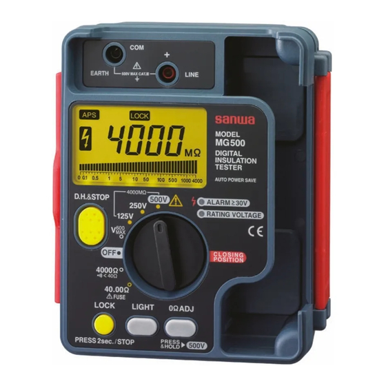
[3] NAMES AND FUNCTIONS OF COMPONENT UNITS
Instrument body
LCD panel
潦
澂
澂
漓
濂
滷
澑
澎
潘
澆
潭
濳
Test lead (TL-112)
潛
潺
Plug
潯
Strap (ST-50)
潸
澁
澀
Name
Description
Grounding/COM terminal for connecting the black
漓
EARTH/COM terminal
alligator clip.
滷
LINE/+ terminal
Line/+ terminal for connecting the red test lead.
Displays the value, function name or voltage output
澆
LCD panel
status.
MΩ measurement function:
• Press and hold the button to output the test voltage.
When the button is released, the test voltage output
is stopped, the circuit under test is discharged
automatically, and the last displayed value appears
on the display together with the
• When the button is pressed during continuous test
voltage generation using the LOCK button, the test
voltage is stopped, the last displayed value is held,
潺
MEASURE button
and the circuit under test is discharged automatically.
40 Ω measurement function:
• Press and hold the button to start measuring. When
the button is released, the test voltage output is
stopped and the last displayed value is held appears
on the display together with the
• When the button is pressed during continuous
measurement
using
measurement is stopped and the last displayed value
is held.
When pressed for more than 2 seconds, continuous
test voltage is output and
release the lock, press the LOCK or MEASURE button,
the test voltage output is stopped, the circuit under test
is discharged automatically, and the last displayed
value appears on the display together with the
780Vrms
indication.
600Vrms
40 Ω measurement function:
潸
LOCK button
When pressed for more than 2 seconds,
indication appears and the tester continues measuring.
To release the lock, press the LOCK or MEASURE
button. The measurement is stopped and the last
displayed value appears on the display together with
the
Turns backlight on/off. The backlight goes off
澁
LIGHT button
automatically after 10 seconds.
Zero Ohm adjustment for 40 Ω measurement function
澀
0Ω ADJ button
or when selecting the maximum MΩ measurement
function.
Turns the tester ON/OFF or to select a function. The
Power/function
潯
body cover cannot be closed unless this switch is set to
switch
the OFF position.
Lights up in MΩ measurement function. It blinks when
RATING VOLTAGE
潛
indicator
the test voltage drops below rated value.
Lights up when the input is about 30 V AC/DC or more.
濳
ALARM indicator
It can be used as the live circuit detection, etc.
潭
Test lead storage space
Space to store the test leads and alligator clips.
澂
Strap hook
To attach a strap.
潼
Numeral and decimal point
潘
AC voltage operation indicator
澎
Negative value indicator
MΩ measurement function:
Lights up when the tester outputs test voltage.
Lights up when the object to be measured is charged
澑
about 30 V or more.
V measurement function:
Lights up when the input is 600 Vrms or more.
DC voltage operation indicator.
濂
澳
澣
澡
澤
Auto Power Save mode indicator
The tester enters "power save mode" automatically if it
has not been operated for about 30 minutes. The tester
澹
come out of "power save mode" when power/function
switch is turned to OFF once and set to the required
function again.
濆
潦
To cancel Auto Power Save function, turn the
潼
power/function switch from OFF position to any desired
function while holding the LIGHT button pressed.
Test pin
*A small electric current from power supply is present
in Auto Power Save mode. Be sure to set the
power/function switch to "OFF" after measurement.
Finger
guard
澳
Data Hold indicator
澣
Test lock (continuous test voltage output) indicator
0 Ω adjustment indicator
澡
Low battery warning indicator:
Appears when the internal batteries are exhausted (to
澤
about 7.2 V or less). When the indicator appears or
blinks, replace the batteries with new ones.
澹
Unit indicators.
Logarithmic bargraph
濆
Disabled in the 40 Ω measurement function
[4] SPECIFICATIONS
4-1 General Specifications
Average value
AC Sensing
LCD
4200 count with log bar graph
Sampling rate
Approx. 2 times / sec.
indication.
Range selection
Auto only
Range up: approx. 4200 count or over,
Range down: approx. 380 count or below
Over-range indication
"OL" indication on LCD
V function: 780V or over
MΩ, 4000Ω, 40Ω function: Approx. 4200 count or over
" − " indication only when negative input
Polarity indication
Low battery indication
"
" lights or flickers at about 7.7V-7.2V or below
Environmental condition
Altitude 2000m or below, pollution degree II
indication.
Operating temperature /
0°C to 40°C and maximum relative humidity 90%
humidity
(No condensation)
the
LOCK
button,
the
Storage temperature /
-10°C ~ 50°C, 70%RH or below (with battery removed).
humidity
Power supply
R6 1.5V x 6 pcs (MG125, MG500) ; LR6 1.5V x 6 pcs (MG1000)
Time of
measurement
indication appears. To
Safety / EMC
Dimensions
Weight
Power consumption
Accessories
Optional accessories
4-2 Measurement Range and Accuracy
Temperature 23 ± 5
indication.
rdg: Reading. dgt: Digits
4-2-1 Insulation resistance measurement functions (kΩ , MΩ)
Model:MG1000
Nominal test voltage &
Measurement Range
250V
4.000MΩ/40.00MΩ
400.0MΩ/4000MΩ
500V
4.000MΩ/40.00MΩ
400.0MΩ/4000MΩ
1000V
4.000MΩ/40.00MΩ
400.0MΩ/4000MΩ
Open circuit voltage 1 to 1.3 times of nominal test voltage
Rated measurement current 1.0-1.2 mA (250 V @0.25 MΩ, 500 V @0.5 MΩ, 1000 V @1 MΩ)
Short-circuit current 2mA or less
Live circuit detection At ≧ 30V AC/DC or more, inhibits test, buzzer sounds and
Model:MG500
Nominal test voltage &
Measurement Range
125V
400.0kΩ
4.000MΩ/40.00MΩ
400.0MΩ/4000MΩ
250V
400.0kΩ
4.000MΩ/40.00MΩ
400.0MΩ/4000MΩ
500V
400.0kΩ
4.000MΩ/40.00MΩ
400.0MΩ/4000MΩ
Open circuit voltage 1 to 1.3 times of nominal test voltage
Rated measurement current 1.0-1.2 mA (125 V @0.125 MΩ, 250 V @0.25 MΩ, 500 V @0.5 MΩ)
Short-circuit current 2mA or less
Live circuit detection At ≧ 30V AC/DC or more, inhibits test, buzzer sounds and
Model:MG125
Nominal test voltage &
Measurement Range
25V
400.0kΩ/4.000MΩ
40.00MΩ/400.0MΩ
50V
400.0kΩ/4.000MΩ
40.00MΩ/400.0MΩ
125V
400.0kΩ/4.000MΩ
40.00MΩ/400.0MΩ
Open circuit voltage 1 to 1.3 times of nominal test voltage
Rated measurement current 1.0-1.2 mA (25V@ 0.025MΩ, 50V@0.05MΩ, 125V@0.125MΩ)
Short-circuit current 2mA or less
Live circuit detection At ≧ 30V AC/DC or more, inhibits test, buzzer sounds and
Note
When the displayed value is 2000 MΩ or more, the lowermost digit is fixed at 0.
MG125, MG500 : Approx. 5 hours
MG1000 : Approx. 2 hours 30 minutes
IEC61010-1 CAT.III 600V, IEC61557-1/2/4, IEC61326 (EMC),
IEC60529-IP54, IEC61010-031 (TL-112)
170 (L) X 142 (W) X 57 (H)
Approx. 600g (battery included)
Apporox. 7mA at V function
Battery (built-in), test leads (TL-112), Strap (ST-50), instruction manual
Alligator clip CL-16
°
C, humidity 45% to 75% RH.
Center
Measurement Range
Accuracy
scale
1st effective
0.5∼20.00MΩ ±(3%rdg+4dgt)
measurement range
10MΩ
2nd effective
0∼0.49MΩ
20.01∼4000MΩ ±(5%rdg+5dgt)
measurement range
1st effective
1.000∼500MΩ ±(3%rdg+4dgt)
measurement range
100MΩ
0∼0.999MΩ
2nd effective
501∼4000MΩ ±(5%rdg+5dgt)
measurement range
1st effective
2.000∼1000MΩ ±(3%rdg+4dgt)
measurement range
100MΩ
0∼1.999MΩ
2nd effective
1001∼4000MΩ ±(5%rdg+5dgt)
measurement range
ALARM indicator lights up.
Center
Measurement Range
Accuracy
scale
1st effective
20.0kΩ∼10.00MΩ
±(3%rdg+4dgt)
measurement range
10MΩ
0∼19.9kΩ
2nd effective
±(5%rdg+5dgt)
measurement range
10.01∼4000MΩ
1st effective
50.0kΩ∼20.00MΩ
±(3%rdg+4dgt)
measurement range
100MΩ
0∼49.9kΩ
2nd effective
±(5%rdg+5dgt)
measurement range
20.01∼4000MΩ
1st effective
1∼500MΩ
±(3%rdg+4dgt)
measurement range
100MΩ
0∼0.999MΩ
2nd effective
±(5%rdg+5dgt)
measurement range
501∼4000MΩ
ALARM indicator lights up.
Center
Measurement Range
Accuracy
scale
1st effective
10.0kΩ∼5.00MΩ
±(3%rdg+4dgt)
measurement range
1MΩ
0∼9.9kΩ
2nd effective
±(5%rdg+5dgt)
measurement range
5.01∼400.0MΩ
1st effective
10.0kΩ∼5.00MΩ
±(3%rdg+4dgt)
measurement range
1MΩ
2nd effective
0∼9.9kΩ
±(5%rdg+5dgt)
measurement range
5.01∼400.0MΩ
1st effective
20.0kΩ∼10.00MΩ
±(3%rdg+4dgt)
measurement range
1MΩ
0∼19.9kΩ
2nd effective
±(5%rdg+5dgt)
measurement range
10.01∼400.0MΩ
ALARM indicator lights up.
Advertisement

Related Manuals for Sanwa MG1000


Summary of Contents for Sanwa MG1000
- Page 1 For example, when measuring an electrical path of 100 V, it is humidity recommended to use a tester with a rated measuring voltage of 125 V. is held. Power supply R6 1.5V x 6 pcs (MG125, MG500) ; LR6 1.5V x 6 pcs (MG1000)
- Page 2 Accuracy Input Resistance Max. Overload Protection 6-4-1 Battery replacement: R6 1.5V x 6pcs (MG125, MG500) ; LR6 1.5V x 6pcs (MG1000) 0.05 Ω. If “OL” is displayed, replace the fuse as it may be 2. Connect the test lead to the object to be measured.
Need help?
Do you have a question about the MG1000 and is the answer not in the manual?
Questions and answers
como configurar para 1000v