Table of Contents
Advertisement
Quick Links
Advertisement
Table of Contents

Subscribe to Our Youtube Channel
Related Manuals for Sanwa DCM2000DR


Summary of Contents for Sanwa DCM2000DR
- Page 1 DCM2000DR DIGITAL CLAMP METER INSTRUCTION MANUAL...
-
Page 2: Table Of Contents
EF (Electric Field ) sensing ……………………………… 【6】MAINTENANCE Maintenance and Inspection …………………………… Calibration and Inspection ……………………………… Storage …………………………………………………… Battery Replacement …………………………………… 【7】AFTER-SALE SERVICE Warranty and Provision ………………………………… Repair ……………………………………………………… SANWA web site ………………………………………… 【8】SPECIFICATIONS General Specifications ………………………………… Measuring ranges and accuracies ……………………... -
Page 3: Warning Messages For Safe Use
*Before use, read the following safety precautions. This instruction manual explains how to use your digital clamp meter equipped with the DMM facility DCM2000DR. Before use, please read this manual thoroughly to ensure correct and safe use. After reading it, keep it together with the product for reference to it when necessary. -
Page 4: 2】Applications And Features
2. Voltages over DC 70 V or AC 33 Vrms (46.7 V peak) are hazardous to human body. Take care so as not to touch them. 3. Never input signals exceeding the maximum rated input value (see 1-3). 4. Never use the meter for measuring voltages of lines connected to equipment (e.g. -
Page 5: Overload Protection
1-3 Overload Protection Input Max. rated Max. overload Functions terminals input protection input ・ DC/AC 1000 V DC/AC 1100 V ・ - (Black), + (Red) Voltage input DC/AC 1100 V ・ inhibited Clamp sensor DC/AC 2000 A DC/AC 2000 A section —... -
Page 6: Applications
[2] APPLICATIONS AND FEATURES 2-1 Applications This instrument is an AC/DC clamp meter/digital multimeter of the RMS value response type, designed for measurements in the range specified by IEC 61010-1 CAT. IV, 1000 V. It is suitable for current and voltage measurements of low- voltage circuitry, electric equipment and power supply facilities. -
Page 7: Main Unit And Test Leads
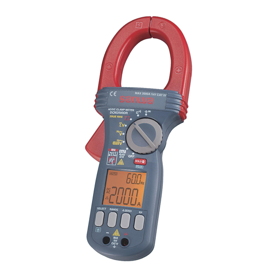
[3] NAMES OF COMPONENT UNITS 3-1 Main unit and test leads Location of Clamping current non-contact sensor (CT) EF antenna Barrier Current measurement center position/polarity Power/function indicator switch Function Trigger button (See Chapter 4.) Display Input terminal for Input terminal for functions other functions other than DCA/ACA,... - Page 8 3-2 Display Sub value (Frequency) display Units Main value display : Auto range : VFD :Low battery indication : Peak measurement mode : Circuit continuity check : Diode : Low input impedance : Data Hold : Direct Current : Alternate Current :...
-
Page 9: Power Switch & Function Switch
[4] DESCRIPTION OF FUNCTIONS 4-1 Power Switch & Function Switch Turn this switch to turn on and off the power and select a measuring function. 4-2 Auto power save Auto power save reduces the battery power consumption by turning the display off automatically in about 34 minutes after the last operation made on this instrument. - Page 10 4-6 Range Hold: button When the button is pressed, the meter is set in the manual mode and the range is fixed. (“ ” disappears from the display.) In the manual mode, each time this button is pressed, the range changes. While checking the unit and decimal point on the display, select the best range.
- Page 11 • When the button is pressed in the Peak Hold mode, light and the value displayed at that moment is held. Even the displayed value is held, the peak value continues to be updated internally so, when the button is pressed again to release the held value, the latest updated peak value is displayed.
-
Page 12: Ef (Electric Field) Sensing
4-10 EF (Electric Field) sensing: EF button For details, see section 5-9, “EF (Electric Field) sensing”. 4-11 Muting the buzzer Any buzzer sound can be muted by turning the power/function switch to ON button depressed. The muting of the buzzer sound while holding the is indicated by the change of the main value display from 8888 to 0000. -
Page 13: Start-Up Inspection
[5] MEASURING PROCEDURE WARNING 1. Do not apply an input signal exceeding the maximum rated value of each function. 2. During measurement, do not change the function switch. 3. During measurement, do not touch the test pin side of the barrier of the test probe or the part past the barrier of the clamp sensor. - Page 14 Function Input Ranges ±DC 1.500-1000 V 6.000/60.00/600.0/1000 V AC 1.500-1000 V 6.000/60.00/600.0/1000 V 600.0/6.000 k/60.00 k/600.0 k 0.0 Ω - 10.00 MΩ Ω /6.000 M/40.00 MΩ *The accuracy-guaranteed frequencies of the measurement are from 50 to 60 Hz. ① Use the test leads for measurement. This function measures the input by automatically identifying the type from the resistance (Ω), AC voltage (ACV) and DC voltage (DCV).
- Page 15 Notes: • The fixed function can be selected with the button. The auto identification mode can be confirmed with [ ] lit on the main value display when there is no input signal. • When the button is pressed once while a measurement value is displayed, the current function (Ω, DCV or ACV) and range are fixed and the instrument is put to the manual range mode (...
-
Page 16: Vfd (Variable Frequency Drive) Ac Voltage Measurement
VFD (Variable Frequency Drive) AC voltage measurement WARNING This function uses a low-pass filter to cut high frequencies. As there is a possibility that a voltage higher than the displayed value exists, first measure the voltage with to confirm that there is no hazardous voltage before selecting the function. -
Page 17: Ac Voltage Measurement (Acv)
AC voltage measurement (ACV) Function Input Ranges 0.000 ~ 1000 V 6.000/60.00/600.0/1000 V 40.0 ~ 1999 Hz 199.9/1999 Hz ① Use the test leads for measurement. ② The frequency (Hz) input sensitivity is determined by the range being used for display. A different input sensitivity can also be selected manually by pressing the button. -
Page 18: Dc Voltage / Dc Voltage + Ac Voltage Measurement (Dcv/ Dcv+Acv)
DC voltage / DC voltage + AC voltage measurement (DCV/ DCV+ACV) Function Input Ranges ±0.000-1000 V 6.000/60.00/600.0/1000 V 0.000-1000 V 6.000/60.00/600.0/1000 V DCV+ACV 10.0-1999 Hz 199.9/1999 Hz *The frequency is not displayed when DCV is more than 50 % of ACV. -
Page 19: Current (A) Measurements (Aca/Dca/Dca+Aca)
Current (A) measurements (ACA/DCA/DCA+ACA) CAUTION 1. To improve the measurement accuracy, position the measured conductor as close as possible to the center of the clamp sensor. 2. Always clamp around a single wire at a time. Correct current measurement is impossible if multiple wires, a cable with multiple conductors or parallel cords are clamped. - Page 20 5-6-1 AC current measurement (ACA) Function Input Ranges 0.0-2000 A 200.0/2000 A 20.0-400 Hz 199.9/1999 Hz *The accuracy-guaranteed frequencies of this measurement are from 40 to 400 Hz. ① Press the button so that lights. ② Open the clamp sensor, position the wire to be measured and close the clamp sensor completely.
-
Page 21: Resistance Measurement / Circuit Continuity Check
5-6-3 DC current + AC current measurement (DCA+ACA) Function Input Ranges DCA + ACA 0.0-2000 A 200.0/2000 A 20.0-400 Hz 199.9/1999 Hz *The frequency is not displayed when DCV is more than 50 % of ACV. ① Press the button so that both light. -
Page 22: Capacitance Measurement / Diode Test
Capacitance measurement / Diode test ( WARNING Never apply an external voltage to the measurement terminals. CAUTION 1. Discharge the measured capacitor before measurement. 2. Since this instrument measures the capacitance by applying current to the measured capacitor, it is not suitable for measuring a capacitor with high leak current such as an electrolytic capacitor. -
Page 23: Ef (Electric Field ) Sensing
5-9 EF (Electric Field ) sensing CAUTION 1. Before EF sensing, check the operation of the instrument using a known power source. 2. During EF sensing, do not hold the instrument by a position beyond the barrier. 3. Even when no voltage is sensed, this does not always mean that no voltage exists because a voltage below the sensing threshold may exist. -
Page 24: Maintenance And Inspection
If any of the above problems exists, stop using the meter and request for repair. 6-2 Calibration and Inspection For more information, please contact Sanwa’s authorized agent / distribute service provider, listed in our website. See section 7-3. 6-3 Storage CAUTION 1. -
Page 25: Battery Replacement
6-4 Battery Replacement Batteries when the meter is shipped: A battery for monitoring has been installed prior to shipment from the factory. It may be discharged before the expiration of the described battery life. *The battery for monitoring is a battery used to check the functions and performance of the product. -
Page 26: Warranty And Provision
Sanwa authorized agent or distributor. Sanwa reserves the right to inspect all warranty claims to determine the extent to which the warranty policy shall apply. This warranty shall not apply to disposables batteries, or any product or parts, which have been subject to one of the following causes: 1. -
Page 27: Sanwa Web Site
5 times or more in volume and fill cushion materials fully and then clearly mark “Repair Product Enclosed” on the box surface. The cost of sending and returning the product shall be borne by the customer. 7-3 SANWA web site http://www.sanwa-meter.co.jp E-mail: exp_sales@sanwa-meter.co.jp — 25 —... -
Page 28: General Specifications
[8] SPECIFICATIONS 8-1 General Specifications Δ- Σ method Operation method AC detection method True RMS Main value: Max. 6000 count Display Sub value (frequency): Max. 1999 count Sampling rate Approx. 5 times/sec. Over-range display "OL" is displayed Range switching Auto, manual Polarity switching Auto (Only “-“... -
Page 29: Measuring Ranges And Accuracies
Environment under over 3 V/m field intensity: Accuracy not guaranteed. Instruction manual, test leads (TL-29), carrying Accessories pouch (C-DCM2000DR) 8-2 Measuring ranges and accuracies Accuracy-guaranteed temperature/humidity ranges: 23 ±5 °C, no more than 80 %RH (without condensation) rdg: Reading. dgt: Lowest digit. - Page 30 DCV+ACV (DC voltage + AC voltage): The AC frequency is from 50 to 400 Hz. Ranges Accuracy 6.000 / 60.00 /600.0 / 1000 V ±(1.4 %rdg + 7 dgt) Note: The input impedance is about 10 MΩ at 50 pF. (AUTO Ω...
- Page 31 DCA+ACA (DC current + AC current) Ranges Frequency Accuracy 200.0 A DC or ±(3.0 %rdg + 8 dgt) 50-60 Hz 2000 A 200.0 A ±(3.5 %rdg + 5 dgt) 40-49.9 Hz 2000 A 0-1000 A 60.1-400 Hz 2000 A 1001-2000 A Not specified Note: Accuracy after the zero point is set by pressing the button.
- Page 32 Circuit continuity check The buzzer beeps at below the threshold (10 to 200 Ω). Response time: Approx. 32 msec. Capacitance Ranges Accuracy 60.00 nF / 600.0 nF / 6.000 µF ±(2.0 %rdg + 5 dgt) 60.00 µF / 600.0 µF ±(3.5 %rdg + 5 dgt) 2000 µF ±(4.0 %rdg + 5 dgt)
- Page 33 MEMO...
- Page 34 本社 = 東京都千代田区外神田2−4−4・電波ビル 郵便番号 = 101-0021・電話 = 東京 (03) 3253−4871㈹ 大阪営業所 = 大阪市浪速区恵美須西2−7−2 郵便番号 = 556-0003・電話 = 大阪 (06) 6631−7361㈹ SANWA ELECTRIC INSTRUMENT CO.,LTD. Dempa Bldg., 4-4 Sotokanda2-Chome Chiyoda-Ku,Tokyo,Japan 大豆インキを使用しています。 01 - 1310 2040 6010 This manual emplys soy ink.
Need help?
Do you have a question about the DCM2000DR and is the answer not in the manual?
Questions and answers