Table of Contents
Advertisement
Advertisement
Table of Contents

Related Manuals for Sanwa PC710


Summary of Contents for Sanwa PC710
-
Page 2: Table Of Contents
[7] AFTER-SALE SERVICE Multimeter and Test Leads Display Warranty and Provision [4] DESCRIPTION OF FUNCTIONS Repair Power Switch/Function Selector SANWA web site Auto Power Saving [8] SPECIFICATIONS Low Battery Indication General Specifications Measuring Function Selection Measuring Range and Accuracy Electric Field Detection... -
Page 3: Explanation Of Warning Symbols
This instruction manual explains how to use your digital multimeter 1. Do not use the instrument if the meter or test leads look damaged. PC710. Before using, read through this manual to reduce the risk 2. Be sure to use the specified fuse. -
Page 4: Overload Protection
1-3 Overload Protection [2] APPLICATIONS AND FEATURES 2-1 Applications Measuring Function Max. Rated Input Overload Protection Terminal This instrument is a portable digital multimeter designed to measure light electric circuits. The instrument offers not only 1000V dc/ac 1050V rms, 1450V peak 「... -
Page 5: Parts Identification
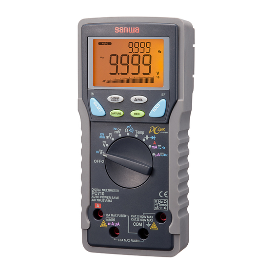
[3] Parts Identification How to detach the light shielding magnet cap Light shielding magnet cap 3-1 Multimeter and Test Leads Light shielding magnet cap Optical communication unit connector LCD display ⇒ Range hold button Select button (Back light button) Turn the light shielding magnet cap counterclockwise to detach. Crest capture button Relative button MAX/MIN/AVG... -
Page 6: Display
3-2 Display [4] DESCRIPTION OF FUNCTIONS ⑤ ⑥ ⑮ ⑭ ⑩ ⑪ ② 4-1 Power Switch/Function Selector Turn the switch to turn on/off the power and select a measuring ⑦ function. All segments of the LCD display will be turned on for 1 seconds after power-on, and then the meter will be ready to use. -
Page 7: Low Battery Indication
4-2-2 How to disable the Auto Power Saving :[ μ ] ⇒ [ μ /μ ] ⇒ [ μ /Hz ] ⇒ [ μ ] ⇒ … 「 」 ・ Press the SELECT button while turning the meter power on. Note: Release the SELECT button after is turned off. -
Page 8: Range Hold
4-9 PC (Personal Computer) Interface 4-6 Range Hold Press the RANGE HOLD button to select manual-ranging, and the The instrument equips with an optical isolated interface port at the meter back for data communication. KB-USB7, dedicated USB meter will remain in the range it was in. ( turns off.) In optical communication unit (separately available), and PCLink7, the manual-ranging mode, press the button again to step through... -
Page 9: Test Leads Improper Connection Warning
4-10 Test Leads Improper Connection Warning 4-13 Relative Measurement The meter beeps as well as displays “InEr” to warn the user Press the △ REL button to activate the relative measurement against possible damage to the meter due to test leads improper mode and △... -
Page 10: Terms
4-15 Terms [5] Measuring procedures Analog bar graph The analog bar graph provides a visual indication of 5-1 Pre-operational Check measurement like a traditional analog meter needle. WARNING True RMS 1. Do not use the instrument if the meter or test leads look True RMS is a term which identifies a DMM that responds accurately to the effective RMS value regardless of the damaged. - Page 11 (Max. rated input voltage: 1,000V dc/ac) START 「 」 AC Voltage ( )/Frequency (Hz) Simultaneous Measurement Damaged WARNING Meter/Test leads damaged? 1. Do not apply any input signal exceeding the max. rated input voltage. 2. Do not switch the function selector while measuring. Looks OK 3.
- Page 12 Hz / / Hz Note: Hz input sensitivity varies automatically with a selected voltage range. 9.999V range has the highest sensitivity and the 999.9V range has the lowest. Auto ranging measurements normally set the most appropriate trigger level. You can also press the RANGE HOLD button to select another trigger level (voltage range) manually.
- Page 13 (Max. rated input voltage: 1,000V dc/ac) 「 」 ・ DC Voltage( ) measurement ・ DC Voltage( )/AC Voltage( ) simultaneous measurement WARNING 1. Do not apply any input signal exceeding the max. rated input voltage. 2. Do not switch the function selector while measuring. 3.
-
Page 14: Duty Cycle ( D%) Measurement
(Max. rated input voltage: 10V dc/ac) 「 」 ・ DC voltage (m ) measurement ・DC Voltage (m )/AC Voltage(m ) simultaneous measurement ・ Logic-level frequency ( ) measurement ・ Duty cycle ( D%) Measurement WARNING 1. Do not apply any input signal exceeding the max. rated input voltage. - Page 15 5-5 (Max. rated input voltage: 600mV dc/ac) 「 」 ・ AC Voltage (m )/Frequency (Hz) Simultaneous Measurement WARNING 1. Do not apply any input signal exceeding the max. rated input voltage. 2. Do not switch the function selector while measuring. 3.
- Page 16 (Do not apply any voltage or current.) 「 」 / Hz Hz / m ・ ・ Conductance (nS) Measurement ・ Continuity Check ( WARNING Do not apply any voltage or current to the measuring terminals. CAUTION In the case of high resistance measurement, readings may be unstable due to external inductive influence.
- Page 17 3) Measuring procedure ① Connect the red plug of the test lead to measuring terminal and the black one to the COM terminal. ② Set the function selector to ③ Press the SELECT button to select a function you want to perform. ④...
-
Page 18: Temperature Measurement
(Max. rated input voltage: 50mV dc) 「 」 Temp Temp ・ Temperature measurement ( ℃ ) or ( F ) ( For K-type thermocouple) WARNING 1. Pay attention in order to avoid risk of burn depending on the object temperature or measuring environment. 2. -
Page 19: Capacitance ( ) Measurement, Diode
(Do not apply any voltage or current.) 「 」 ・ Capacitance ( ) measurement ・ Diode ( ) test WARNING 1. Do not apply any voltage or current to the measuring terminals. 2. Measuring live circuit may damage the meter. 5-8-1 Capacitance ( ) measurement CAUTION... - Page 20 5-8-2 Diode ( ) test What to measure (Diode test): Judging the diode (Good or defective) Measuring procedure Connect the red plug of the test lead to measuring ① terminal and the black one to the COM terminal. Set the function selector to , then press the SELECT ②...
-
Page 21: (Hz) Measurement
, 5-9-1 Current (mA/μA) measurement 「 」 「 」 ・ DC current (m ,μ , ) measurement (m , m , μ , μ Max. rated input current 600mA dc/ac) ・ AC current (m , μ )/Frequency(Hz) simultaneous measurement 1) What to measure ・... - Page 22 Note: Measuring Frequency (Hz) μ / μ μ Frequency range Range Input sensitivity(Sine wave) 600.0μA 60μA 6000μA 600μA 15.00Hz ∼ 3.000kHz 60.00mA 40mA 600.0mA 60mA 5-9-2 Current (A) measurement ( , Max. rated input current AC 10A dc/ac ) 1) What to measure (DC current): DC circuit current ・...
- Page 23 μ / Hz m / Hz / Hz Note: ・ > 6A: Cool down more than 3 minutes after measuring 1 minute. < 6A Continuable Measuring Frequency (Hz) Frequency range range Input sensitivity (Sine wave) 6.000A 15.00Hz ∼ 3.000kHz 10.00A ―...
-
Page 24: Measurements With Separately Available Accessories
5-10 Measurements with Separately Available Accessories terminal and the black one to the COM terminal. ② Set the function selector to , then press the SELECT WARNING button to select /Hz. ③ Press the RANGE button to set the 9.999V range. 1. - Page 25 Note: To make temperature measurement, connect the temperature 5-10-3 DC Clamp probe: CL-33D probe to the PC710 connected to the PC on which sanwa's (Max. measurable current 300A dc) software PC Link7 is installed and running. 2) Measuring range 1) What to measure -50 ∼...
-
Page 26: Maintenance
[6] MAINTENANCE agent/distribution service provider, listed in our website.See section 7-3. WARNING 1. The followings are important to safety. Read this manual throughly to maintain the instrument. 6-3 Battery and Fuse Replacement 2. Calibrate and inspect the instrument at least once a year to WARNING ensure safety and maintain its accuracy. -
Page 27: Storage
φ6.3×32mm Breaking capacity : 50kA This warranty policy is valid within the country of purchase only, Part number : F1198 Screw and applied only to the product purchased from Sanwa authorized for the battery door Fuse 12.5A/500V agent or distributor. -
Page 28: 7-3 Sanwa Web Site
[8] SPECIFICATIONS provider, listed in our website, in your country with above information. An instrument sent to Sanwa / agent / distributor 8-1 General Specifications without above information will be returned to the customer. Operation Delta-sigma modulation method Note: 9,999 counts:... -
Page 29: 8-2 Measuring Range And Accuracy
8-2 Measuring Range and Accuracy IEC61010-1:2001 Accuracy: ±(% rdg + dgt) IEC61010-031:2008 rdg: reading, dgt: least significant digit Category II for 1000V ac and dc Temperature: 23 ℃ ±5 ℃ , Humidity: <75% R.H. Safety Category III for 600V ac and dc True RMS voltage and current accuracies are specified from 10% Compliances Category II for 500V ac and dc... - Page 30 AC Voltage ACV DC/AC Voltage (DC/AC V) for dual display Range Accuracy AC voltage (ACV)/ Frequency (Hz) for dual display 50Hz ∼ 60Hz Range Accuracy 60.00mV, 600.0mV ± (0.7% rdg + 6dgt) 50Hz ∼ 60Hz 9.999V, 99.99V, 999.9 60.00mV, 600.0mV, 9.999V, 40Hz ∼...
- Page 31 AC current (ACA), DC/AC current (DC/AC A) Temp (℃ & F)** Range Accuracy Input resistance** Range Accuracy* DC, 50Hz ∼ 60Hz -50 ℃ ∼ 1000 ℃ 0.3% rdg + 2 ℃ 600.0μA F ∼ 1832 0.3% rdg + 5 6000μA ±(0.6% rdg +3dgt)...
- Page 32 Non-Contact EF-Detection Capacitance Typical Voltage Tolerance EF-Strength Indication Range Accuracy* 10V ∼ 36V 60.00nF, 600.0nF*** ±(0.8% rdg + 3dgt) − 23V ∼ 83V 6.000μF ±(1.0% rdg + 3dgt) −− 110V 59V ∼ 165V 60.00μF ±(2.0% rdg + 3dgt) −−− 220V 124V ∼...
Need help?
Do you have a question about the PC710 and is the answer not in the manual?
Questions and answers