Table of Contents
Advertisement
Advertisement
Table of Contents

Related Manuals for Sanwa LCR700


Summary of Contents for Sanwa LCR700
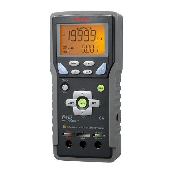
- Page 1 LCR700 DIGITAL LCR METER INSTRUCTION MANUAL...
-
Page 2: Table Of Contents
Warranty and Provision ………………………………… 34 Measuring Mode Selection ………………………………… 8 Repair ……………………………………………………… 34 4-5-1 Auto LCR Mode ……………………………………………… 8 SANWA web site ………………………………………… 35 [8] SPECIFICATIONS 4-5-2 Manual LCR Mode and DC Resistance Measurement …… 9 Measuring Frequency Selection ………………………… 10 8-1 General Specifications ……………………………………... -
Page 3: Safety Precautions
*Before use, read the following safety precautions. WARNING This instruction manual explains how to use your LCR meter LCR700. The following instructions are intended to prevent injury such as Before using, read through this manual to reduce the risk of fire , electric shock and so on. -
Page 4: Applications And Features
[2] APPLICATIONS AND FEATURES [3] PART IDENTIFICATION 2-1 Applications 3-1 LCR meter and clipping leads LCR700 is a full-featured high-performance handy LCR meter which rivals the capabilities and options of many of its bench ⑰ ⑱ ① ⑯ counterparts. This instrument features a device value sorting function, allowing users to quickly sort passive devices in situations such as incoming inspections. -
Page 5: Display
Clipping leads CL-700 (Bundled item) 3-2 Display ① ② ③ ④ ⑤ ⑥ ⑦ ㉓ Plugs ㉒ Alligator clips ⑧ ㉑ ⑳ ⑨ ⑲ ⑱ ⑩ ⑰ ⑯ ⑮ ⑭ ⑬ ⑫ ⑪ SMD Clipping leads CL-700SMD (Separately available accessory) ①... -
Page 6: Power Switch
[4] DESCRIPTION OF FUNCTIONS 4-5 Measuring Mode Selection 4-5-1 Auto LCR Mode 4-1 Power Switch After power-on, the meter is in the Auto LCR mode as a default Press the POWER button to turn on the meter. All segments of the setting, and shows [AUTO LCR] on the display. -
Page 7: Manual Lcr Mode And Dc Resistance Measurement
4-5-2 Manual LCR Mode and DC Resistance Measurement Quality factor (Q) As already described, the default setting is the Auto LCR mode after = Inductance (L) component / Resistance (R) component power-on, the main function can be switched to the manual LCR mode Dissipation factor (D) or DC resistance mode by pressing the L/C/R AUTO/MANU button. -
Page 8: Series/Parallel Mode
4-7 Series/Parallel Mode The meter uses the following formula to calculate relative When measuring L/C/R with multiple element in its equivalent circuit, measurements. an appropriate measuring mode needs to be selected, assuming REL% = (DCUR – DREF) / DREF * 100% actual circuit to be measured. -
Page 9: Open/Short Calibration
4-11 OPEN/SHORT Calibration 3. Insert the bundled shorting plate to the The OPEN/SHORT calibration before measurement reduces the parasitic directly connectable measuring terminals. effect of the test fixture to get better accuracy especially for high/low 4. Press the CAL button again. The display shows [Srt]. - Page 10 [Measurement using the clipping leads "CL-700"] 4. Connect the test leads to make a short circuit. 1. Make sure the leads are completely 5. Press the CAL button again. disconnected. The display shows [Srt]. 2. Press the CAL button for 2 seconds. 6.
-
Page 11: Device Sorting
4-12 Device Sorting The display shows the readings. The meter can sort device values into PASS/FAIL based on resistance, capacitance, or inductance. This feature is useful in situations such as incoming inspections for mass production parts. Note: This function is not available in the Auto LCR mode. Use this function in the manual LCR mode. -
Page 12: Measuring Principles
4-15 MEASURING PRINCIPLES 4-15-2 Impedance measurement Impedance can be measured in series or in parallel. 4-15-1 What is impedance? In parallel mode, impedance can be represented as reciprocal of Impedance Z extends the concept of resistance to AC, which is admittance (Y). -
Page 13: Principles Of Open/Short Calibration
[5] MEASURING PROCEDURE Both Rs and Rp are part of the equivalent circuit of capacitors and inductors. 5-1 Connection of DUT (Device Under Test) To measure capacitance and inductance, refer to the settings as DUT's (Devices Under Test) may be connected to the meter as follows. shown in the table below. -
Page 14: Pre-Operational Check
• Attach the SMD clipping leads "CL-700SMD" 5-2 Pre-operational Check (separately available accessory). WARNING 1. Do not use the instrument if the meter or the clipping leads look damaged. 2. Make sure the clipping leads are not broken. CAUTION • Make sure the battery condition is good after power-on. Replace the battery with new one if the battery power is low. -
Page 15: Auto Lcr Mode Measurement
5-3 Auto LCR Mode Measurement 5-4 Manual LCR Mode measurement WARNING WARNING 1. Do not apply any voltage or current to the measuring terminals. 1. Do not apply any voltage or current to the measuring terminals. 2. Measuring live circuit may damage the meter. 2. -
Page 16: Inductance (L) Measurement
5-4-1 Inductance (L) measurement 5-4-2 Capacitance (C) measurement 1) Measuring ranges 1) Measuring ranges C: 200.00 pF ~ 20.00 mF (auto-range) L: 20.000 μH ~ 2000 H (auto-range) 2) Measuring procedure 2) Measuring procedure ① Press the L/C/R AUTO/MANU button to select Ls or Lp function. ①... -
Page 17: Resistance (R) Measurement
5-4-3 Resistance (R) measurement 5-5 Device Value Sorting 1) Measuring ranges 1) Measuring ranges R: 20.000 Ω ~ 200.0 MΩ (auto-range) L: 20.000 μH ~ 2000 H (auto-range) C: 200.00 pF ~ 20.00 mF (auto-range) 2) Measuring procedure R: 20.000 Ω ~ 200.0 MΩ (auto-range) ① Press the L/C/R AUTO/MANU button to select Rs or Rp function. ②... -
Page 18: Simple Examination
[6] MAINTENANCE WARNING 1. The followings are important to safety. Read this manual throughly to maintain the instrument. 2. Calibrate and inspect the instrument at least once a year to ensure safety and maintain its accuracy. The following shows how to set up the details of the sorting mode. a. -
Page 19: Storage
Battery (1) year from the date of purchase. This warranty policy is valid within the country of purchase only, and applied only to the product purchased from SANWA authorized agent or distributor. Screw for the battery door SANWA reserves the right to inspect all warranty claims to determine the extent to which the warranty policy shall apply. -
Page 20: Specifications
[8] SPECIFICATIONS information. An instrument sent to SANWA / agent / distributor without above information will be returned to the customer. 8-1 General Specifications Main display 20,000 counts: Ls / Lp / Cs / Cp / Rs / Rp / DCR Note:... -
Page 21: Measuring Range And Accuracy
8-2 Measuring Range and Accuracy Temperature [0.15 x (specified accuracy)]/℃ 0 ~ 18 ℃ , 28 ~ 50 ℃ Accuracy: ±(% rdg + dgt) " % + d " is an abbreviation. coefficient rdg: reading Operating 0 ~ 50 ℃ < 80 % RH dgt: least significant digit temperature/ Temperature: 23 ℃ ±5 ℃ humidity Humidity: ≦ 80 % R.H. Storage -20 ~... - Page 22 Inductance: Lp, Ls (When D < 0.1) Accuracy of Θ θe: θe=±(180/π) × Ae (deg) Ae means an accuracy of rdg in the main display. Range Resolution 100/120 Hz 1 kHz 10 kHz 100 kHz 20 μH 0.001 μH 1.0 % + 10 d • In the capacitance measurement 200 μH 0.01 μH 0.8 % + 10 d 1.0 % + 10 d 2000 μH 0.1 μH 0.8 % + 10 d 0.5 % + 5 d 0.8 % + 10 d Range...
- Page 23 Accuracy of D value De: De = ±Ae < MEMO > Ae means an accuracy of rdg in the main display. Ex. Capacitor to be measured: 180 nF Test frequency: 1 kHz Measuring accuracy: ±(0.3 %rdg + 3 dgt) Ae = 0.3 %rdg Calculation for De (Accuracy of D value): De= ±0.003 Accuracy of ESR: Re = ±Z ×Ae(Ω) Calculation for Z : 1/(2πfC) or 2πfL...
- Page 24 本社 = 東京都千代田区外神田2−4−4・電波ビル 郵便番号 = 101-0021・電話 = 東京 (03) 3253−4871㈹ 大阪営業所 = 大阪市浪速区恵美須西2−7−2 郵便番号 = 556-0003・電話 = 大阪 (06) 6631−7361㈹ SANWA ELECTRIC INSTRUMENT CO.,LTD. Dempa Bldg., 4-4 Sotokanda2-Chome Chiyoda-Ku,Tokyo,Japan This manual employs soy ink. 01-1301 5008 6010...
Need help?
Do you have a question about the LCR700 and is the answer not in the manual?
Questions and answers