Table of Contents
Advertisement
Quick Links
INSTALLATION AND OPERATION MANUAL
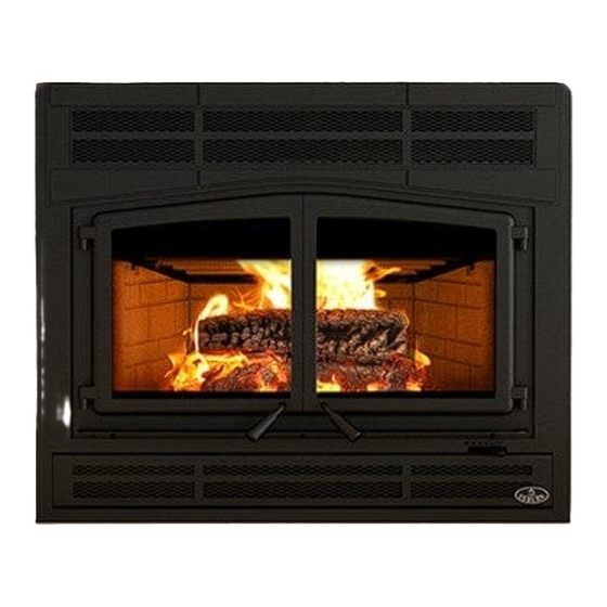
HORIZON
(OB04010 model)
US ENVIRONMENTAL PROTECTION AGENCY
PHASE II CERTIFIED WOOD FIREPLACE
Listed to standards ULC-S610 and UL 127
www.osburn-mfg.com
Manufactured by:
Stove Builder International Inc.
250 rue Copenhague, Saint-Augustin-de-Desmaures (Quebec), Canada, G3A 2H3
After-sale service: 418-908-8002
E-mail: tech@sbi-international.com
READ AND KEEP THIS MANUAL FOR REFERENCE
This manual is available for free download on the manufacturer's web site. It is a copyrighted document.
Re-sale is strictly prohibited. The manufacturer may update this manual from time to time and cannot be
responsible for problems, injuries, or damages arising out of the use of information contained in any manual
obtained from unauthorized sources.
45857A
Printed in Canada
2021-08-18
Advertisement
Table of Contents

Related Manuals for Osburn OB04010K


Summary of Contents for Osburn OB04010K
- Page 1 INSTALLATION AND OPERATION MANUAL HORIZON (OB04010 model) US ENVIRONMENTAL PROTECTION AGENCY PHASE II CERTIFIED WOOD FIREPLACE Listed to standards ULC-S610 and UL 127 www.osburn-mfg.com Manufactured by: Stove Builder International Inc. 250 rue Copenhague, Saint-Augustin-de-Desmaures (Quebec), Canada, G3A 2H3 After-sale service: 418-908-8002 E-mail: tech@sbi-international.com READ AND KEEP THIS MANUAL FOR REFERENCE This manual is available for free download on the manufacturer’s web site.
- Page 2 THANK YOU FOR CHOOSING THIS OSBURN WOOD FIREPLACE As one of North America’s largest and most respected wood stove and fireplace manufacturers, Stove Builder International takes pride in the quality and performance of all its products. We want to help you get maximum satisfaction as you use this product.
-
Page 3: Table Of Contents
TABLE OF CONTENT PART A - OPERATION AND MAINTENANCE ....................6 Safety Information ........................... 6 Summary of Operation and Maintenance Cautions and Warnings .............6 General Information ......................... 8 Appliance performance ........................8 General features ..........................9 Measurements ...........................10 Zone heating and how to make it work for you ................12 The benefits of low emissions and high efficiency ................12 The SBI commitment to you and the environment ................12 2.6.1... - Page 4 4.3.9 How to place the logs ........................23 Maintaining Your Wood Heating System ..................24 Fireplace maintenance ........................24 5.1.1 Plated finish maintenance ......................24 5.1.2 Glass door cleaning ........................24 5.1.3 Door adjustment ..........................25 5.1.4 Door alignment ..........................26 5.1.5 Replacing the door gasket ......................27 5.1.6 Replacing the door glass.........................28 5.1.7...
- Page 5 Appendix 8 – Electrical Wiring ....................... 74 Appendix 9 - Exploded Diagram and Parts List ..................76 OSBURN LIMITED LIFETIME WARRANTY ....................81 REGISTER YOUR WARRANTY ONLINE To receive full warranty coverage, you will need to show evidence of the date you purchased your stove.
-
Page 6: Part A - Operation And Maintenance
PART A - OPERATION AND MAINTENANCE 1 SAFETY INFORMATION Summary of Operation and Maintenance Cautions and Warnings CAUTION - OPERATION • USING A FIREPLACE WITH CRACKED OR BROKEN COMPONENTS, SUCH AS GLASS OR FIREBRICKS OR BAFFLES MAY PRODUCE AN UNSAFE CONDITION AND MAY DAMAGE THE FIREPLACE. •... - Page 7 CAUTION - INSTALLATION • DO NOT INSTALL THE FIREPLACE OUTDOORS. • THE FIREPLACE AND CHIMNEY MUST BE IN AN ENCLOSURE UP TO THE ATTIC. • SOME JURISDICTIONS IN THE USA REQUIRE A SUPPLY OF OUTDOOR COMBUSTION AIR FOR THE FIREPLACE. IN CANADA, AN OUTDOOR AIR SUPPLY IS NOT REQUIRED, IF A CARBON MONOXIDE (CO) DETECTOR/ALARM IS LOCATED IN THE ROOM IN WHICH THE FIREPLACE IS INSTALLED.
-
Page 8: General Information
GENERAL INFORMATION Appliance performance Fuel type Dry cordwood Recommended heating area 1,000 to 2,800 ft (93 to 260 m Firebox volume 4,28 ft (0,113 m Maximum burn time 11 h 16,900 BTU/h to 43,000 BTU/h (2)(3) Overall heat output rate (min. to max) (5.0 kW to 12,6 kW) Average overall efficiency - Dry cordwood... -
Page 9: General Features
General features Maximum log length 25 in (635 mm) east-west* Flue outlet diameter 8 in (203 mm) Chimney diameter 8 in (203 mm) Type of chimney CAN/ULC S629, UL 103 HT (2100 °F) Baffle material C-Cast Approved for alcove installation Not approved Approved for mobile home installation‡... -
Page 10: Measurements
Measurements HORIZON – Installation and Operation Manual... - Page 11 HORIZON – Installation and Operation Manual...
-
Page 12: Zone Heating And How To Make It Work For You
Zone heating and how to make it work for you Your new Horizon wood fireplace is a space heater, which means it is intended to heat the area it is installed in, as well as spaces that connect to that area, although to a lower temperature. This is called zone heating and it is an increasingly popular way to heat homes or spaces within homes. -
Page 13: What Is Your New Fireplace Made Of
2.6.1 What is your new fireplace made of? The body of your fireplace, which is most of its weight, is carbon steel. Should it ever become necessary many years in the future, almost the entire fireplace can be recycled into new products, thus eliminating the need to mine new materials. -
Page 14: How To Prepare Or Buy Good Firewood
3.1 How to prepare or buy good firewood 3.1.1 What is good firewood? Good firewood has been cut to the correct length for the fireplace, split to a range of sizes and stacked in the open until its moisture content is reduced to 15% to 20%. 3.1.2 Tree species The tree species the firewood is produced from is less important than its moisture content. -
Page 15: Piece Size
3.1.4 Piece size Firewood dries more quickly when it is split. Large unsplit rounds can take years to dry enough to burn. Even when dried, unsplit logs are difficult to ignite because they don’t have the sharp edges where the flames first catch. -
Page 16: Judging Firewood Moisture Content
3.1.6 Judging firewood moisture content You can find out if some firewood is dry enough to burn by using these guidelines: • Cracks form at the ends of logs as they dry; • As it dries in the sun, the wood turns from white or cream colored to grey or yellow; •... -
Page 17: Operating Your Fireplace
4 OPERATING YOUR FIREPLACE This wood heater has a manufacturer-set minimum low burn rate that must not be altered. It is against federal regulations to alter this setting or otherwise operate this wood heater in a manner inconsistent with operating instructions in this manual. 4.1 Your first fires Two things will happen as you burn your first few fires: the paint cures and the internal components of the fireplace are conditioned. -
Page 18: Two Parallel Logs
DO NOT LEAVE THE FIREPLACE UNATTENDED WHEN THE DOOR IS SLIGHTLY OPENED. ALWAYS CLOSE AND LATCH THE DOOR AFTER THE FIRE IGNITES. After the kindling fire has mostly burned, you can add standard firewood pieces until you have a fire of the right size for the conditions. -
Page 19: Ash Removal
4.3.2 Ash removal Ash should be removed from the firebox every two or three days of full time heating. Do not let the ash build up in the firebox because it will interfere with proper fire management. The best time to remove ash is after an overnight fire when the fireplace is relatively cool, but there is still some chimney draft to draw the ash dust into the fireplace and prevent it from coming into the room. -
Page 20: Shutting Down The Air Supply
4.3.5 Shutting down the air supply The fireplace can operate at three different settings: Maximum combustion rate, medium combustion rate and finally low combustion rate. At the low combustion rate setting, the fireplace is operated with an air control system that regulates the combustion. The maximum combustion rate setting is usually for cold startup and when maximum heat is desired (Position A). - Page 21 In the B position, it is also possible to close the air supply manually if a power failure occurs by pushing the small lever to the left. HORIZON – Installation and Operation Manual...
-
Page 22: Building Different Fires For Different Needs
4.3.6 Building different fires for different needs Using the air control is not the only way to match the fireplace’s heat output to the heat demand. Your house will need far less heat in October than in January to be kept at a comfortable temperature. If you fill the firebox full in fall weather, you will either overheat the space or turn the fireplace down so much that the fire will be smoky and inefficient. -
Page 23: Maximum Burn Cycle Times
4.3.8 Maximum Burn Cycle Times The burn cycle time is the period between loading wood on a coal bed and the consumption of that wood back to a coal bed of the same size. The flaming phase of the fire lasts for roughly the first half of the burn cycle and the second half is the coal bed phase during which there is little or no flame. -
Page 24: Maintaining Your Wood Heating System
5 MAINTAINING YOUR WOOD HEATING SYSTEM Fireplace maintenance Your new fireplace will give many years of reliable service if you use and maintain it correctly. Some of the internal components of the firebox, such as refractory slabs, baffles and air tubes, will wear over time under intense heat. -
Page 25: Door Adjustment
5.1.3 Door adjustment In order for your fireplace to burn at its best efficiency, the door must provide a perfect seal with the firebox. Therefore, the gasket should be inspected periodically to check for a good seal. The gasket seal may be improved with a simple latch mechanism adjustment. -
Page 26: Door Alignment
5.1.4 Door alignment To align, open the fireplace’s doors and loosen the pressures screws located on the lower and upper hinges of each door using a 3/32” Allen key to free the adjustable hinge rods. Using a flat screwdriver, turn the adjustable hinge rods in the direction shown to adjust the doors. Tighten all door hinge pressure screws when they are at the desired positions. -
Page 27: Replacing The Door Gasket
5.1.5 Replacing the door gasket It is important to maintain the gaskets in good condition. After a year or more of use, the door gaskets will compress and become hard, which may allow air to leak past it. You can test the condition of the door gaskets by closing and latching the door on a strip of paper. -
Page 28: Replacing The Door Glass
1400º F. If the glass breaks, it must be replaced with one having the same specification. Contact your Osburn dealer to obtain a genuine replacement part (see “replacement parts”, in appendix to get the proper part number). -
Page 29: Cleaning And Painting The Fireplace
5.1.6.1 Replacing the door glass gasket The gasket must be centred on the edge of the glass. To do this easily, peel back a section of the paper covering the adhesive and place the gasket on a table with the adhesive side up. Stick the end of the gasket to the middle of one edge, then press the edge of the glass down onto the gasket, taking care that it is perfectly centred on the gasket. -
Page 30: How Often Should You Clean The Chimney
5.2.2 How often should you clean the chimney? It is not possible to predict how much or how quickly creosote will form in your chimney. It is important, therefore, to check the build-up in your chimney monthly when getting used to the new fireplace until you determine the rate of creosote formation. -
Page 31: Fire Baffle Removal Prior To Cleaning The Chimney
The chimney should be swept following these steps: 1) Remove the fire baffle and air tubes. 2) Remove the rain cap. 3) Sweep the chimney. 4) Clean the inside of the firebox. 5) Re-install the baffle, the air tubes and the rain cap. CAUTION OPERATION OF YOUR HORIZON WITHOUT THE BAFFLE MAY CAUSE UNSAFE AND HAZARDOUS TEMPERATURE CONDITIONS AND WILL VOID THE WARRANTY. -
Page 32: Part B - Installation
PART B – INSTALLATION Install the fireplace only as described in these instructions and using only components from the chimney manufacturers listed in TABLE 4. Parts Required • HORIZON Fireplace • Prairie Style Faceplate • Classic moulded refractory brick panels •... -
Page 33: Regulations Covering Fireplace Installation
Regulations covering fireplace installation When installed and operated as described in these instructions, the HORIZON wood fireplace is suitable for use in residential installations. In Canada, the CSA B365 Installation Code for Solid Fuel Burning Appliances and Equipment and the CSA C22.1 Canadian National Electrical Code are to be followed in the absence of local code requirements. -
Page 34: Transportation Packaging
6.3.2 Transportation packaging To facilitate transportation of the HORIZON fireplace before installation, we have designed a transportation packaging that allows reducing the weight. The fireplace refractory panels are in a box you can carry separately. We suggest you install the refractory panels after the setting up of the fireplace. To install the refractory panels, see Appendix 5 - Refractory Slabs Replacement. -
Page 35: Hearth Extension Construction Options
CLEARANCES* 6" (152 mm) 8" (203 mm) 24" (610 mm) *Measurements are from the door opening. Side Mantle Wall in front of fireplace: 48" Ceiling: 84 in. (2.13 m) measured from the base of the fireplace. Fireplace enclosure: Back: 0" Sides: 0"... - Page 36 6.3.5.1 Option #1 - Installation directly on the floor • A 2.00 R value for the hearth extension is required. The non-combustible hearth extension floor area must extend at least 32" (813 mm) (B) in front of the hearth. • The joint between the hearth extension and the fireplace (E), for the entire width of the floor protection, must be protected by a bent and continuous piece of sheet metal (not included).
- Page 37 " 6.3.5.2 Option #2 - Installation raised less than 8 from floor • A 2.00 R value for the hearth extension is required. The non-combustible hearth extension floor area must extend at least 32" (813 mm) (B) in front of the hearth. •...
- Page 38 6.3.5.3 Option #3 - Installation on a more than 8" raised base • When installed on a more than 8" (203 mm) raised base (C), A 2.00 R value for the hearth extension is required. The non-combustible hearth extension floor area must extend at least 16" (406 mm) (B) in front of the hearth.
- Page 39 6.3.5.4 Option #4 - Installation raised between 8" and 12" from floor • A 1.00 R value for the hearth extension is required. The non-combustible hearth extension floor area must extend at least 20" (508 mm) (B) in front of the hearth. •...
- Page 40 6.3.5.5 Option #5 - Installation raised more than 12" from floor • No R value for the hearth extension is required. The non-combustible hearth extension floor area must extend at least 16" (406 mm) (B) in front of the hearth. •...
- Page 41 6.3.5.6 R Calculations The use of an R value is convenient when more than one material is going to be used in the hearth extension to cover the combustible surface. This is because R values are additive, whereas K values are not. To find the corresponding R factor to use for some selected materials, please see Table 1 : Thermal Characteristics of Common Floor Protection Materials*.
-
Page 42: Minimum Heart Extension Requirements
* Information as reported by manufacturers and other resources. ** For a 1/8" thickness. You cannot «stack» horizontal still air to accumulate R-values; you must separate each layer of horizontal still air with another non-combustible material. 6.3.6 MINIMUM HEART EXTENSION REQUIREMENTS R factor Option Installation type required... -
Page 43: Framing Construction
6.3.7 Framing construction 6.3.7.1 Framing The construction of the framing, facing, and mantel must be in accordance with the standards and the following instructions: Frame the sides and back of the fireplace using 2" × 3" (5 cm x 8 cm) or heavier lumber. However, the front studs as well as headers on top of the fireplace must be of a depth no more than the depth of the top standoffs. - Page 44 NON-COMBUSTIBLE FRAMING (STEEL STUD) CLEARANCE 84" (2.13m) This section must remain empty Non-combustible material Non-combustible finishing material Refer to the building code or the local code for regulations concerning the need to install finishing material inside the chase around the fireplace. NOTE THIS FIREPLACE IS BUILT IN ORDER TO MAINTAIN A 1/2"...
- Page 45 6.3.7.2 Framing when installing a fresh air intake kit or a forced air kit • See Appendix 4 - Installing the Fresh Air Intake Kit for installation instructions of a fresh air intake kit (L). • See section Appendix 2 - Forced Air Distribution Kit* (VA4460 for more details on installing the forced air kit (K).
-
Page 46: Facing
6.3.7.3 Framing for a corner installation CAUTION VALUES (M) AND (N) ARE MINIMUM MEASUREMENTS. THEY MAY NEED TO BE INCREASED TO ALLOW INSTALLATION OF A FRESH AIR INTAKE KIT OR FORCED AIR KIT, OR DEPENDING ON THE FINISH MATERIAL USED. MEASUREMENTS* 67 5/8"... -
Page 47: Installation Of A Non-Combustible Shelf
MEASURMENTS 84" (2134mm) 50 3/4" (1289mm) 3 1/16" (78 mm) 3" (76 mm) LEGEND Combustible material allowed in this area Non-combustible material only in this area 6.3.9 Installation of a non-combustible shelf It is possible to install a shelf but it must be made of non combustible materials. It must be installed at at least 52"... -
Page 48: The Venting System
7 THE VENTING SYSTEM General The venting system, acts as the engine that drives your wood heating system. Even the best fireplace will not function safely and efficiently as intended if it is not connected to a suitable chimney. The heat in the flue gases that pass from the fireplace into the chimney is not waste heat. This heat is what the chimney uses to make the draft that draws in combustion air, keeps smoke inside the fireplace and safely vents exhaust to outside. -
Page 49: Chimney Installation Notes
There are two reasons why the chimney in the house at right will cold backdraft when it is cold outside and there is no fire burning in the fireplace. First, the chimney runs up the outside of the house, so the air in it is colder and denser than the warm air in the house. - Page 50 HORIZON – Installation and Operation Manual...
- Page 51 • For installations where more than one chimney is located in the same non-chase or within the same area, we suggest that their terminations be separated by at least 16" (410 mm) horizontally, and 18" (460 mm) vertically. This separation is to prevent smoke migrating from one chimney to another. 18"...
-
Page 52: Chimney Installation Instructions
Chimney Installation Instructions Always refer to the chimney manufacturer’s Installation manual to ensure a safe installation. Some non- illustrated parts may be required. 7.6.1 Examples of typical chimney installation Straight Installation Exterior offset installation Connection to a masonry chimney HORIZON – Installation and Operation Manual... -
Page 53: Exterior Offset Installation
7.6.2 Exterior offset installation insure good draft, recommended to have a length of 18 inches from the top of the unit to the first offset. However, starting using a 30° or 45° elbow is also approved. Mandatory measure of 15 ft. from the bottom of the fireplace to the top of the outside chimney. - Page 54 1. Cut and frame the holes in the ceiling, floor and roof where the chimney will pass. Use a plumb bob to line up the center of the holes. Make sure that the size of the floor and ceiling holes are in accordance with the chimney manufacturer’s instructions.
-
Page 55: Offset Chimney Installation
7.6.4 Offset chimney installation TABLE 2 : MINIMUM SYSTEM HEIGHT WHEN USING OFFSETS Fireplace model HORIZON Chimney model All models (see TABLE 3) Vertical installation 15 ft. (4.6 m) Two (2) offsets 15 ft. (4.6 m) Four (4) offsets 17 ft. (5.2 m) After reaching the location requiring the elbow, proceed as follows: 1. - Page 56 TABLE 4 : LISTED CHIMNEYS FOR YOUR HORIZON CHIMNEY BRAND TYPE INNER DIAMETER MANUFACTURER Olympia Chimney / Ventis 1" Solid Pack 8" (20 cm) SBI Venting Division SBI Venting Division Nexvent 1" Solid Pack 8" (20 cm) Olympia Chimney Champion Chimney System 1" Solid Pack 8"...
-
Page 57: Rafter Protection
2" Solid Pack : Dura Tech Premium, Dura Plus HTC AC Triple Wall : Dura Plus • Chimney cannot be enclosed at the American Metal AC Triple wall: HS, HSS attic level. 7.6.5 Rafter protection Rafter protectors, at the roof level, must be installed with this unit, if the chimney is enclosed at the attic level. -
Page 58: Universal Offset Support
For roof support installation, refer to the instructions provided with the support by the chimney manufacturer. Many manufacturers will provide the maximum height of chimney that can be supported by the support. Make sure you respect those parameters. 7.8.2 Universal offset support This support is used to support the chimney above an offset. -
Page 59: Installation Instructions
7.9.1 Installation instructions 1. Position the fireplace in its location. Temporarily install the elbow or chimney section (A) on the top of the fireplace and, using a level, mark with an oval the location where the flue liner will enter the masonry chimney. 2. - Page 60 Some states or counties require that fireplace are connected to a fresh air intake. If you install a fresh air intake on an external wall, its pressure may vary in windy conditions. It would be therefore preferable not to install the air intake on a heavily windward wall. If you experience difficulties with your fireplace and you suspect strong winds as the source of the problem, a mechanical damper with help you diagnose and solve the problem.
-
Page 61: Appendix 1 - Warm Air Circulation Grille - Modern Style (Ac01378)
APPENDIX 1 - WARM AIR CIRCULATION GRILLE – MODERN STYLE (AC01378) It is possible to connect a warm air circulation grille kit in the fireplace facing. This kit allows distributing heat to the room using natural convection. For the complete installation procedure, see the installation manual provided with the kit. -
Page 62: Appendix 2 - Forced Air Distribution Kit* (Va4460)
APPENDIX 2 - FORCED AIR DISTRIBUTION KIT* (VA4460) It is possible to connect a forced air distribution kit on either sides of the HORIZON. This kit allows distributing heat to another room up to 50 feet (15 m) of the fireplace. The insulated flexible pipe (not included in the kit) must be HVAC type pipe and must comply with ULC S110 and/or UL 181, Class 0 or Class 1 Standards and must withstand temperatures up to 250 °F. - Page 63 WARNING • IN CANADA, THE TERMINATION GRILL MUST BE INSTALLED AT LEAST 59" (150CM) FROM THE FLOOR (B). • A 1" CLEARANCE TO COMBUSTIBLE MATERIALS (A) MUST BE LEFT AROUND THE TERMINATION GRILL. For the complete installation procedure, see the installation manual provided with the kit. You can also download this manual on the web site.
-
Page 64: Appendix 3 - Blower Maintenance Or Replacement
APPENDIX 3 - BLOWER MAINTENANCE OR REPLACEMENT 1. Open the bottom louver (A). 2. With a short square head screwdriver, remove the 4 screws (C) holding in place the heat shield (B). 3. Remove and keep the heat shield (B) and the 4. - Page 65 5. Unplug the blower’s electric wires (F) and (G). 6. Lift the blower (E) located under the firebox towards the back. 7. Turn 90° to pull out. Repeat the steps in reverse order to reinstall the blower. HORIZON – Installation and Operation Manual...
-
Page 66: Appendix 4 - Installing The Fresh Air Intake Kit
APPENDIX 4 - INSTALLING THE FRESH AIR INTAKE KIT During operation, the fireplace requires fresh air for combustion and draws air out of the house. It may starve other fuel burning appliances such as gas or oil furnaces. As well, exhaust fans may compete for air, causing negative pressure in the house, resulting in smoke entering the house from the fireplace. - Page 67 The fresh air intake kit may be installed on two different places on the fireplace. 1- On the right side of the appliance (most common). 2- On the right side under the appliance. 1. Remove the knock out located on the right-hand side of your fireplace. 2.
- Page 68 3. Flip the fireplace lower decorative louver. Install the blocking plate (F) included with the fireplace, on the front opening of the air control housing. Using a screwdriver, secure with four screws located in the user’s manual. Then, install the flexible pipe* (D) (not supplied) to the fresh air intake adapter (B) using one of the adjustable pipe clamps (C).
- Page 69 WARNING TO AVOID CONDENSATION AND RUST IN YOUR FIREPLACE, IT IS RECOMMENDED TO USE AN INSULATED PIPE LONG ENOUGH (MINIMUM 10FT) AND CONTAINING A "P-TRAP". This configuration can be found inside the chase, but must at all times maintain clearances to combustibles. The following figure is shown as an example.
-
Page 70: Appendix 5 - Refractory Slabs Replacement
APPENDIX 5 - REFRACTORY SLABS REPLACEMENT The intense heat of the fire will normally cause hairline cracks in the refractory slabs. These cracks can be minimized by proper curing as described in “First Fires”. They will not normally diminish the effectiveness of the refractory slabs. -
Page 71: Appendix 6 - Installation Of Secondary Air Tubes And Baffle
APPENDIX 6 - INSTALLATION OF SECONDARY AIR TUBES AND BAFFLE REMOVABLE PARTS Cotter pins (x4) Air tubes (x4) C-Cast baffle (x1) 1. Remove the inner ash retainer and the floor 2. Using a power screwdriver and hex tip 5/16", refractory slab (A & B). remove the slab holder (D) and the left refractory slab (C). - Page 72 3. Starting with the rear tube, lean and insert the right 4. Align the notch in the left end of the tube end of the secondary air tube into the rear right with the tab of the left air channel hole. channel hole.
-
Page 73: Appendix 7 - Air Control Snap Disc Replacement
APPENDIX 7 – AIR CONTROL SNAP DISC REPLACEMENT 1. Remove the inner ash retainer and the floor 2. Using a power screwdriver and hex tip 5/16", refractory slab (A & B). remove the slab holder (D) and the left refractory slab (C). -
Page 74: Appendix 8 - Electrical Wiring
APPENDIX 8 – ELECTRICAL WIRING Have the wiring installed by a qualified electrician. Connect the wires from the power outlet to the terminal block, making sure that the white wire matches the white wire on the terminal. Connect the black wire with the black wire of the terminal block. - Page 75 HORIZON – Installation and Operation Manual...
-
Page 76: Appendix 9 - Exploded Diagram And Parts List
APPENDIX 9 - EXPLODED DIAGRAM AND PARTS LIST HORIZON – Installation and Operation Manual... - Page 77 IMPORTANT: THIS IS DATED INFORMATION. When requesting service or replacement parts for your stove, please provide the model number and the serial number. We reserve the right to change parts due to technology upgrade or availability. Contact an authorized dealer to obtain any of these parts. Never use substitute materials.
- Page 78 Item Description 21490 PILOT INSULATION SE68758 PILOT ASSEMBLY 30094 HEX SCREW WASHER HEAD 1/4-20 X 3/4" F ZINC TYPE PL68759 INNER ASH RETAINER 30767 SPRING 1/2'' OUTSIDE DIA. X 8''L PL60266 LONG TOP STANDOFF PL68952 SIDE STANDOFF VA4460 FORCED AIR DISTRIBUTION KIT 60201 CONNECTOR 1 SCREW 3/8"...
- Page 79 Item Description PL68765 CENTER SECONDARY AIR TUBE 30068 STAINLESS STEEL COTTER PIN 1/8" X 1 1/2" 21265 BAFFLE (C-CAST) PL68850 BAFFLE DEFLECTOR 30060 THREAD-CUTTING SCREW 1/4-20 X 1/2" F HEX STEEL SLOT WASHER C102 ZINC OA10630 PRAIRIE STYLE FACEPLATE AC01378 WARM AIR CIRCULATION GRILLE - MODERN STYLE 30540 HOT AIR GRAVITY DISTRIBUTION KIT GRILL...
- Page 80 HORIZON – Installation and Operation Manual...
-
Page 81: Osburn Limited Lifetime Warranty
Labour cost and repair work to the account of the manufacturer are based on a predetermined rate schedule and must not exceed the wholesale price of the replacement part. Shall your unit or a components be defective, contact immediately your OSBURN dealer. To accelerate processing of your warranty claim, make sure to have on hand the following information when calling: •... - Page 82 HORIZON – Installation and Operation Manual...
Need help?
Do you have a question about the OB04010K and is the answer not in the manual?
Questions and answers