Unigas HP60 Manual Of Installation - Use - Maintenance
Double stage lpg - light oil burners
Hide thumbs
Also See for HP60:
- Manual of installation - use - maintenance (96 pages) ,
- Manual (36 pages) ,
- Manual of installation - use - maintenance (66 pages)

Subscribe to Our Youtube Channel
Related Manuals for Unigas HP60


Summary of Contents for Unigas HP60
- Page 1 HP60 - HP65 HP72 - HP73A Double stage LPG - light oil burners MANUAL OF INSTALLATION - USE - MAINTENANCE BURNERS - BRUCIATORI - BRULERS - BRENNER - QUEMADORES - ГОРЕЛКИ M039311CA Rel. 0.3 07/2016...
-
Page 2: General Introduction
DANGERS, WARNINGS AND NOTES OF CAUTION THIS MANUAL IS SUPPLIED AS AN INTEGRAL AND ESSENTIAL PART OF THE PRODUCT AND MUST BE DELIVERED TO THE USER. INFORMATION INCLUDED IN THIS SECTION ARE DEDICATED BOTH TO THE USER AND TO PERSONNEL FOLLOWING PRODUCT INSTALLATION AND MAINTENANCE. -
Page 3: Directives And Standards
3b) FIRING WITH GAS, LIGHT OIL OR OTHER FUELS DIRECTIVES AND STANDARDS Gas burners GENERAL European directives The burner shall be installed by qualified personnel and in compliance -Regulation 2016/426/UE (appliances burning gaseous fuels) with regulations and provisions in force; wrong installation can cause -2014/35/UE (Low Tension Directive) injuries to people and animals, or damage to property, for which the -2014/30/UE (Electromagnetic compatibility Directive) -
Page 4: Symbols Used
Burner data plate Type Gas - Light oil burners For the following information, please refer to Model Year European Directives the data plate: S.Number -Regulation 2016/426/UE (appliances burning gaseous fuels) burner type and burner model: must be Output Oil Flow -2014/35/UE (Low Tension Directive) reported in any communication with the Fuel... -
Page 5: General Features
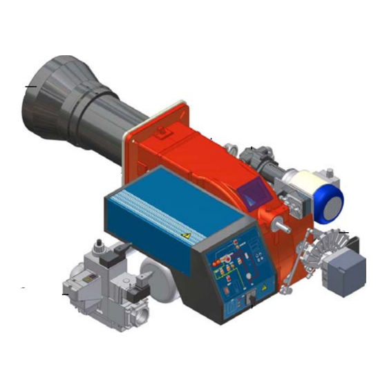
C.I.B. UNIGAS - M039311CA PART I: INSTALLATION GENERAL FEATURES This series represents monobloc gas burners made in die-cast aluminium housing, that can burn either gas or light oil, thanks to the adjustable combustion head which allows a good performance with both fuels. They can be provided in progressive or fully-modulating version. - Page 6 C.I.B. UNIGAS - M039311CA How to interpret the burner “Performance curve” To check if the burner is suitable for the boiler to which it must be installled, the following parameters are needed: furnace input, in kW or kcal/h (kW = kcal/h / 860);...
-
Page 7: Gas Connection
Burners are identified by burner type and model. Burner model identification is described as follows. Type HP60 Model (1) BURNER TYPE HP60 - HP65 - HP72 - HP73A (2) FUEL L - LPG G - Light oil (3) OPERATION (Available versions) - Page 8 C.I.B. UNIGAS - M039311CA BURNER TYPE HP65...0.32 HP65...0.40 HP65...0.50 HP65...0.65 270 - 970 Output min. - max. kW LPG - Light oilLPG - Light oil Fuel Gas category 3B/P min. - max. kW (Stm 10.5 - 37 Gas rate min. - max. mbar...
- Page 9 C.I.B. UNIGAS - M039311CA BURNER TYPE HP72...1.40 HP72...1.50 HP72...1.65 HP72...1.80 330 - 1550 Output min. - max. kW LPG - Light oil Fuel Gas category 3B/P min. - max. (Stm 12.7 - 59.6 Gas rate min.- max. mbar (see Note 2) Gas pressure min.- max.
- Page 10 Overall dimensions (mm)
- Page 11 O - min O - max HP60 LG..0.32 1100 HP60 LG..0.40 1100 HP60 LG.. 0.50 1100 HP60 LG.. 0.65 1100 362 1115 685 HP65 LG.. 0.32 1156 139 382 1022 588 HP65 LG..1.32 1156 139 382 1148 674 HP65 LG.. 0.40...
- Page 12 C.I.B. UNIGAS - M039311CA Performance Curves HP60 HP65 HP72 ...0.xx HP72 ..1.xx HP73A LG..1.xx 1000 1500 2000 2500 To get the input in kcal/h, multiply value in kW by 860. Data are referred to standard conditions: atmospheric pressure at 1013mbar, ambient temperature at 15°C...
- Page 13 C.I.B. UNIGAS - M039311CA Pressure in the network - gas rate curvesMOUNTINGS AND CONNECTIONS Packing Burners are despatched in cardboard packages and whose dimensions: 1280mm x 850mm x 760mm (L x P x H) Packing cases of this kind are affected by humidity and are not suitable for stacking. The fol- lowing are placed in each packing case: burner with gas train detached;...
- Page 14 C.I.B. UNIGAS - M039311CA meter or shorter than those described in the diagram, please contact the supplier, to verify that a correct matching is possible, with respect of the application involved. To correctly match the burner to the boiler verify the necessary input and the pressure in combu- stion chamber are included in the burner performance curve;...
- Page 15 C.I.B. UNIGAS - M039311CA Gas train connections The next diagrams show the components of the gas train included in the delivery and which must be fitted by the installer.The diagrams are in compliance with the current laws. ATTENTION: BEFORE EXECUTING THE CONNECTIONS TO THE GAS PIPE NETWORK, BE SURE THAT THE MANUAL CUTOFF VALVES ARE CLOSED.
-
Page 16: Assembling The Gas Train
C.I.B. UNIGAS - M039311CA Assembling the gas train gas supply network ”direction” arrows for installation Keys 1A..1E Gasket Gas filter Gas valves group Bellow joint Manual valve Fig. 6 - Example of gas train To mount the gas train, proceed as follows: 1-a) in case of threaded joints: use proper seals according to the gas used;... - Page 17 C.I.B. UNIGAS - M039311CA Siemens VGD20.. and VGD40.. gas valves - with SKP2.. (pressure governor) Mounting When mounting the VGD.. double gas valve, two flanges are required (as for VGD20.. model, the flanges are threaded); to prevent cuttings from falling inside the valve, first fit the flanges to the piping and then clean the associated parts;...
- Page 18 C.I.B. UNIGAS - M039311CA Pressure adjusting range The pressure adjusting range, downstream the gas valves group, changes according to the spring provided with the valve group. Keys 1 spring 2 cap Siemens SKP actuator Siemens VGD valves with SKP actuator:...
- Page 19 C.I.B. UNIGAS - M039311CA Hydraulic diagrams for light oil supplying circuits Fig. 16 - Gravity circuit Fig. 17 - Ring circuit Fig. 18 - Suction circuit Manual valve Light oil filter Light oil feeding pump One way valve Flexible hoses Relief valve NOTE: in plants where gravity or ring feed systems are provided, install an automatic interception device (see n.
- Page 20 C.I.B. UNIGAS - M039311CA Installation diagram of light oil pipes PLEASE READ CAREFULLY THE “WARNINGS” CHAPTER AT THE BEGINNING OF THIS MANUAL. From tank To tank Fig. 19 - Double-pipe system The burner is supplied with filter and flexible hoses, all the parts upstream the filter and downstream the return flexible hose, must be installed by the customer.
- Page 21 An external filter should always be installed in the suction line upstream of the fuel unit. Light oil pumps The pumps provided with these burners can be: HP60 - HP65: Suntec AJ6 HP72: Suntec E7/Danfoss RSF41 HP73A: Suntec TA2 / Danfoss KSM50...
- Page 22 C.I.B. UNIGAS - M039311CA Danfoss RSF41 Oil viscosity 2,5 ÷ 450 cSt Oil temperature -10 ÷ 120°C Inlet maximum pressure 4 bar Maximum return pressure 4 bar Minimum inlet pressure - 0.45 bar to avoid gasing Rotation speed max. 3600 rpm...
- Page 23 C.I.B. UNIGAS - M039311CA Connecting the light oil flexible hoses To connect the flexible light oil hoses to the pump, proceed as follows, according to the pump provided: remove the closing nuts A and R on the inlet and return connections of the pump;...
- Page 24 C.I.B. UNIGAS - M039311CA Electrical connections Respect the basic safety rules. make sure of the connection to the earthing system. do not reverse the phase and neutral connections. fit a differential thermal magnet switch adequate for connection to the mains.
- Page 25 C.I.B. UNIGAS - M039311CA ADJUSTMENTS Combustion head gas pressure curves depending on the flow rate Curves are referred to pressure = 0mbar in the combustion head! The curves referred to the gas pressure in the combustion head, depending on the gas flow rate, are referred to the burner properly adjusted (percentage of residual O in the flues as shown in the “Recommended combustion values”...
- Page 26 C.I.B. UNIGAS - M039311CA Keys Gas filterl Gas proving system Gas valves Fuel pump Gas Adjusting cam Actuator Fig. 21 Gas Filter The gas filters remove the dust particles that are present in the gas, and prevent the elements at risk (e.g.: burners, counters and regu- lators) from becoming rapidly blocked.
- Page 27 C.I.B. UNIGAS - M039311CA Adjustments - brief description Adjust the air and gas flow rates at the maximum output (“high flame”) first, by means of the air damper and the adjusting cam respec- tively. Check that the combustion parameters are in the suggested limits.
- Page 28 C.I.B. UNIGAS - M039311CA “MAX” head position “MIN” head position“MIN” head drive the burner to the low flame stage by means of the TAB thermostat; In order to change the gas flow rate slacken the nuts DB (Fig. 24) and adjust the opening angle of the gas butterfly valve by rotating the rod TG (clockwise rotation increases gas flow, anticlockwise rotation decreases it).
- Page 29 C.I.B. UNIGAS - M039311CA Calibration of air and gas pressure switches The air pressure switch locks the control box if the air pressure is not the one requested. If it happens, unlock the burner by means of the control box unlock pushbutton, placed on the burner control panel.
- Page 30 C.I.B. UNIGAS - M039311CA Adjustment procedure for light oil operation The light oil flow rate can be adjusted choosing a by-pass nozzle that suits the boiler/utilisation output and setting the delivery and return pressure values according to the ones quoted on the table below and the diagram on Fig. 25 (as far as reading the pressure values, see next paragraphs).
- Page 31 C.I.B. UNIGAS - M039311CA Fig. 25 Example (Bergonzo): if a 220kg/h flow rate BERGONZO nozzle is provided, set the return pressure at 11bar, supply at 20bar on the delivery to get a 220kg/h flow rate. If the return pressure needed is 5bar, instead, act on the V adjusting screw on the pressure...
- Page 32 C.I.B. UNIGAS - M039311CA FLUIDICS KW3...60° NOZZLE SUPPLY PRESSURE = 20 bar. VISCOSITY AT NOZZLE = 5 cSt The nominal size of the nozzle is indicated at the ends of the curve Pressure on return (bar)
- Page 33 C.I.B. UNIGAS - M039311CA FLUIDICS KW3...60° NOZZLE SUPPLY PRESSURE = 20 bar. VISCOSITY AT NOZZLE = 5 cSt The nominal size of the nozzle is indicated at the ends of the curve Pressure on return (bar) Pressure on return (bar)
- Page 34 C.I.B. UNIGAS - M039311CA FLUIDICS KW3...45° NOZZLE SUPPLY PRESSURE = 20 bar. VISCOSITY AT NOZZLE = 5 cSt The nominal size of the nozzle is indicated at the ends of the curve Pressure on return (bar) Pressure on return (bar)
- Page 35 C.I.B. UNIGAS - M039311CA FLUIDICS KW3...45° NOZZLE SUPPLY PRESSURE = 20 bar. VISCOSITY AT NOZZLE = 5 cSt The nominal size of the nozzle is indicated at the ends of the curve Pressure on return (bar) Pressure on return (bar)
- Page 36 C.I.B. UNIGAS - M039311CA Adjustment procedure for light oil operation The light oil flow rate is set by choosing a nozzle that suits the boiler/utilisation output and setting the delivery and return pressure values according to the ones quoted on the table below and the diagram on page 30 (as far as reading the pressure values, see next paragraphs).
- Page 37 C.I.B. UNIGAS - M039311CA 10 To perform the regulation, remove the cap D and loosen the screw V (see Fig. 30), by means of a screwdriver (see Fig. 30). The regulating screw V acts on the return pressurefrom the nozzle. Set the pressure to the minimum value of 5 bar. Read the values on the pressure gauge placed on the regulator’s coupling M.
- Page 38 C.I.B. UNIGAS - M039311CA Berger STA12 B 3.41 Siemens SQN72 AUTO-MAN ST2 = High flame cam I = High flame cam (red) ST0 = Ignition position II = Ignition position (blue) ST1 = Low flame III = Low flame (orange))
- Page 39 C.I.B. UNIGAS - M039311CA OPERATING PRINCIPLE FOR LIGHT OIL CIRCUIT Fig. 31 Fig. 32 - Pre-purge Fig. 33 - Low flame Fig. 34 - High flame Keys Light oil pump Light oil solenoid valve Nozzle Pressure gauge Pressure regulator Nonreturn valve...
-
Page 40: Limitations Of Use
C.I.B. UNIGAS - M039311CA PART II: OPERATION LIMITATIONS OF USE THE BURNER IS AN APPLIANCE DESIGNED AND CONSTRUCTED TO OPERATE ONLY AFTER BEING CORRECTLY CONNEC- TED TO A HEAT GENERATOR (E.G. BOILER, HOT AIR GENERATOR, FURNACE, ETC.), ANY OTHER USE IS TO BE CONSIDE- RED IMPROPER AND THEREFORE DANGEROUS. -
Page 41: Light-Oil Operation
C.I.B. UNIGAS - M039311CA OPERATION ATTENTION: before starting the burner up, be sure that the manual cutoff valves are open and check that the pres- sure upstream the gas train complies the value quoted on paragraph “Technical specifications”. Fuel selection: In order to start the burner with gas or light oil, the operator must commute the selector on the burner control panel on (1) = gas, or (2) = light oil. -
Page 42: Routine Maintenance
C.I.B. UNIGAS - M039311CA PART III: MAINTENANCE At least once a year carry out the maintenance operations listed below. In the case of seasonal servicing, it is recommended to carry out the maintenance at the end of each heating season; in the case of continuous operation the maintenance is carried out every 6 months. - Page 43 C.I.B. UNIGAS - M039311CA Fig. 36 Fig. 35 Fig. 37...
- Page 44 C.I.B. UNIGAS - M039311CA Gas filter maintenance ATTENTION: Before opening the filter, close the manual cutoff valve downstream the filter and bleed the gas; check that inside the filter there is no pressurised gas. To clean or remove the filter, proceed as follows: remove the cap unscrewing the fixing screws (A);...
- Page 45 C.I.B. UNIGAS - M039311CA Removing the combustion head Remove the top H. Disconnect the electrode cables CE. Remove the UV detector out of its housing: disconnect electrode cables and the light oil flexible hoses. Loosen the screws S holding the VR group: screw the VR screw in order to loose the threaded rod C.
- Page 46 C.I.B. UNIGAS - M039311CA Adjusting the electrodes position Adjust the electrodes position, according to the quotes (in mm) shown on the next picture. HP65 HP60 10÷ 6÷7 Fig. 38 Cleaning/replacing the electrodes ATTENTION: avoid the electrodes to get in touch with metallic parts (blast tube, head, etc.), otherwise the boiler operation would be compromised.
-
Page 47: Seasonal Stop
C.I.B. UNIGAS - M039311CA procedure. Cleaning and replacing the detection probe The photocell working life is about 10000 working hours (about 1 year), at max 50°C after which it must be replaced. To clean/replace the detection photocell, proceed as follows: Disconnect the system from the electrical power supply. -
Page 48: Troubleshooting
C.I.B. UNIGAS - M039311CA TROUBLESHOOTING CAUSE / FAULT MAIN SWITCH OPEN ABSENCE OF GAS MINIMUM GAS PRESSURE SWITCH FAULT OR BAD SETTING BOILER THERMOSTATS OPEN OVERLOAD TRIPPED INTERVENTION FUSES INTERVENTION AIR PRESSURE SWITCH FAULT OR BAD SETTING DEFECTIVE CONTROL BOX... -
Page 49: Wiring Diagrams
C.I.B. UNIGAS - M039311CA WIRING DIAGRAMS Refer to the attached wiring diagrams. WARNING 1 - Electrical supply 230V 50Hz 1 a.c./400V 50Hz 3N a.c. 2 - Do not reverse phase with neutral 3 - Ensure burner is properly earthed... -
Page 52: Start-Up Program
APPENDIX SIEMENS LME11/21/22 CONTROL BOX The series of equipment LME.. is used for the starup and supervisione of 1- or 2- stage gas burners. The series LME.. is interchangeable with the series LGB.. and LMG.., all diagrams and accessories are interchangea- START-UP PROGRAM ble. - Page 53 LME11 control sequence LME21 control sequence B´ B´ SB / R SB / R W / GP W / GP (LR) BV2 7101d05/0206 Control sequence Waiting time LME22 control sequence Purge time B´ TSA Ignition safety time SB / R Preignition time W / GP Postignition time...
-
Page 54: Connection Diagram
LME11 connection diagram Connection diagram Error message (alarm) Fuel valve PC control EK2 Remote lockout reset button RESET Flame signal Gas pressure switch Air pressure switch Load controller K2/1 K2/2 Fan motor Control thermostat/pressurestat Safety limit thermostat R / W Limit thermostat /pressure switch Ignition transformer 7101 24 /0606... -
Page 55: Technical Characteristics
CONTROL PROGRAM IN THE EVENT OF FAULT CONTROL BOX LOCKED If a fault occurs, all outputs will immediately be deactivated (in less In the event of lockout, the LME.. remains locked and the red signal lamp than 1s). (LED) will light up.The burner control can immediately be reset. This state After an interruption of power, a restart will be made with the full pro- is also mantained in the case fo mains failure. - Page 56 C.I.B. UNIGAS S.p.A. Via L.Galvani, 9 - 35011 Campodarsego (PD) - ITALY Tel. +39 049 9200944 - Fax +39 049 9200945/9201269 web site: www.cibunigas.it - e-mail: cibunigas@cibunigas.it Note: specifications and data subject to change. Errors and omissions excepted.
Need help?
Do you have a question about the HP60 and is the answer not in the manual?
Questions and answers