
Subscribe to Our Youtube Channel
Related Manuals for Unigas HP20


Summary of Contents for Unigas HP20
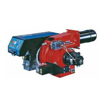
- Page 1 HP20 - HP30 Progressive, Fully-modulating Gas - light oil dual fuel burners MANUAL OF INSTALLATION - USE - MAINTENANCE BURNERS - BRUCIATORI - BRULERS - BRENNER - QUEMADORES - ГОРЕЛКИ M039203CC REL. 2.1 11/2012...
-
Page 2: Table Of Contents
TABLE OF CONTENTS WARNINGS ................................3 PART I: INSTALLATION ............................5 GENERAL FEATURES ................................... 5 How to interpret the burner “Performance curve” ........................... 5 Checking the proper gas train size ..............................6 Matching the burner to the boiler ..............................6 Burner model identification ................................ -
Page 3: Warnings
WARNINGS THIS MANUAL IS SUPPLIED AS AN INTEGRAL AND ESSENTIAL PART OF THE PRODUCT AND MUST BE DELIVERED TO THE USER. INFORMATION INCLUDED IN THIS SECTION ARE DEDICATED BOTH TO THE USER AND TO PERSONNEL FOLLOWING PRO- DUCT INSTALLATION AND MAINTENANCE. THE USER WILL FIND FURTHER INFORMATION ABOUT OPERATING AND USE RESTRICTIONS, IN THE SECOND SECTION OF THIS MANUAL. - Page 4 DIRECTIVES AND STANDARDS 3b) FIRING WITH GAS, LIGHT OIL OR OTHER FUELS Gas burners GENERAL European directives: The burner shall be installed by qualified personnel and in com- - Directive 90/396/CEE - Gas Appliances; pliance with regulations and provisions in force; wrong installation Directive 2006/95/EC on low voltage;...
-
Page 5: Part I: Installation
C.I.B. UNIGAS - M039203CC PART I: INSTALLATION GENERAL FEATURES This series represents monobloc gas burners made in die-cast aluminium housing, that can burn either gas or light oil, thanks to the adjustable combustion head which allows a good performance with both fuels. They can be provided in progressive or fully-modulating version. -
Page 6: Checking The Proper Gas Train Size
C.I.B. UNIGAS - M039203CC Checking the proper gas train size To check the proper gas train size, it is necessary to know the available gas pressure value upstream the burner’s gas valve. Then subtract the backpressure. The result is called p Draw a vertical line matching the furnace input value (600kW, in the example), gas. -
Page 7: Burner Model Identification
C.I.B. UNIGAS - M039203CC Burner model identification Burners are identified by burner type and model. Burner model identification is described as follows. Type HP20 Model (1) BURNER TYPE HP20 - HP30 (2) FUEL M - Natural gas G - Light oil... -
Page 8: Country And Usefulness Gas Categories
C.I.B. UNIGAS - M039203CC Country and usefulness gas categories COUNTRY CATEGORY ES GR SE NO CZ DK GB CY EE MT SK BG RO TR CH 2E( R ) B 2ELL Overall dimensions (mm) B(*S) B(*L) C(*S) C(*L) HP20 HP30... -
Page 9: Performance Curves
Per- formance curve minimum. Pressure in the network - gas rate curves HP20 MG..25 HP30 MG..25/32 Rp 1 (25) Rp 1¼... -
Page 10: Mountings And Connections
C.I.B. UNIGAS - M039203CC MOUNTINGS AND CONNECTIONS Packing Burners are despatched in cardboard packages whose dimensions are: 1280mm x 850mm x 760mm (L x P x H) Packing cases of this kind are affected by humidity and are not suitable for stacking. The fol- lowing are placed in each packing case: burner with gas train detached;... -
Page 11: Gas Train Connections
C.I.B. UNIGAS - M039203CC SIDE UP SIDE DOWN Gas train connections The next diagrams show the components of the gas train included in the delivery and which must be fitted by the installer.The diagrams are in compliance with the current laws. -
Page 12: Assembling The Gas Grain
C.I.B. UNIGAS - M039203CC Assembling the gas grain gas supply network ”direction” arrows for installation Keys 1A..1E Gasket Gas filter Gas valves group Bellow joint Manual valve Fig. 4 - Example of gas train To mount the gas train, proceed as follows: in case of threaded joints: use proper seals according to the gas used;... -
Page 13: Hydraulic Diagrams For Light Oil Supplying Circuits
C.I.B. UNIGAS - M039203CC Hydraulic diagrams for light oil supplying circuits Fig. 9 - Gravity circuit Fig. 10 - Ring circuit Fig. 11 - Suction circuit Manual valve Light oil filter Light oil feeding pump One way valve Flexible hoses Relief valve NOTE: in plants where gravity or ring feed systems are provided, install an automatic interception device (see n. -
Page 14: Light Oil Piping Installation Diagram
C.I.B. UNIGAS - M039203CC Light oil piping installation diagram From tank To tank Fig. 12 (*) Only for installations with gravity, siphon or for- ced circulation feed systems. If the device installed Burner is a solenoid valve, a timer must be installed to Flexible hoses (fitted) delay the valve closing. -
Page 15: Light Oil Pumps
C.I.B. UNIGAS - M039203CC Light oil pumps Pump Suntec AL65 Viscosity range 2 ÷ 12 (cSt) mm Oil temperature 0 ÷ 60 °C Inlet pressure 2 bar Minimum inlet pressure - 0,45 barto avoid gasing Maximum return pressure 2 bar... -
Page 16: Rotation Of Fan Motor And Pump Motor
C.I.B. UNIGAS - M039203CC Fig. 13 Progressive burners Fig. 14Fully modulating burners Probes connection by means of the 7-pins plug (Fig. 16) - see Fig. 15 and the Electric wiring diagrams for connections. Fig. 15 Probes connection Fig. 16 Probe connector:... -
Page 17: Adjustments
C.I.B. UNIGAS - M039203CC ADJUSTMENTS Combustion head gas pressure curves depending on the flow rate Curves are referred to pressure = 0mbar in the combustion head! The curves referred to the gas pressure in the combustion head, depending on the gas flow rate, are referred to the burner properly adjusted (percentage of residual O in the flues as shown in the “Recommended combustion values”... -
Page 18: Gas Filter
C.I.B. UNIGAS - M039203CC ATTENTION: before starting the burner up, be sure that the manual cutoff valves are open and check that the pres- sure upstream the gas train complies the value quoted on paragraph “Technical specifications”. Be sure that the mains switch is closed. - Page 19 C.I.B. UNIGAS - M039203CC Before starting the burner up, drive the high flame actuator microswitch matching the low flame one (in order to let the burner ope- rates at the lowest output) to safely achieve the high flame stage. Start the burner up by means of the thermostat series and wait until the pre-purge time comes to an end and that the burner starts drive the burner to high flame stage, by means fo the thermostat TAB (high/low flame thermostat - see Wiring diagrams), as far as fully-modulating burners, see related paragraph.
-
Page 20: Calibration Of Air And Gas Pressure Switches
C.I.B. UNIGAS - M039203CC 10 The burner is factory-set with the head in its MAX position (maximum output). To let the burner operate at a lower output, turn clockwise the VRT screw and move progressively the combustion head back towards the MIN position. -
Page 21: Adjusting The High Gas Pressure Switch (When Provided)
C.I.B. UNIGAS - M039203CC Adjusting the high gas pressure switch (when provided) To calibrate the high pressure switch, proceed as follows according to its mounting position: remove the pressure switch plastic cover; if the maximum pressure switch is mounted upstreaam the gas valves: measure the gas pressure in the network, when flame is off;... -
Page 22: Adjustment Procedure For Light Oil Operation
C.I.B. UNIGAS - M039203CC Adjustment procedure for light oil operation The light oil flow rate can be adjusted choosing a by-pass nozzle that suits the boiler/utilisation output and setting the delivery and return pressure values according to the ones quoted on the table below (as far as reading the pressure values, see next paragraphs). -
Page 23: Oil Flow Rate Settings
C.I.B. UNIGAS - M039203CC Oil Flow Rate Settings record the high flame value set during the gas operation adjustments (see previous paragraphs). Once the air and gas flow rates are adjusted, turn the burner off, switch the CM switch to the oil operation (OIL, on the burner con- trol panel (see page 26). - Page 24 C.I.B. UNIGAS - M039203CC rate set during the gas operation adjustments (see previous paragraph): checking always the combustion parameters, the adjustment is to be performed by means of the SV2 adjusting cam screw (see picture) when the cam has reached the high flame position.
-
Page 25: Light Oil Circuit
C.I.B. UNIGAS - M039203CC Light oil circuit The fuel is pushed into the pump 1 to the nozzle 3 at the delivery pressure set by the pressure governor. The solenoid valve 2 set the fuel immission into the combustion chamber. The part of fuel that is not burnt goes back to the tank through the return circuit. The fuel amount to be burnt is adjusted by means of the burner actuator according to the adjustments set (see prevoius paragraph). -
Page 26: Part Ii: Operation
C.I.B. UNIGAS - M039203CC PART II: OPERATION LIMITATIONS OF USE THE BURNER IS AN APPLIANCE DESIGNED AND CONSTRUCTED TO OPERATE ONLY AFTER BEING CORRECTLY CON- NECTED TO A HEAT GENERATOR (E.G. BOILER, HOT AIR GENERATOR, FURNACE, ETC.), ANY OTHER USE IS TO BE CONSI- DERED IMPROPER AND THEREFORE DANGEROUS. -
Page 27: Light Oil Operation
C.I.B. UNIGAS - M039203CC Few seconds after the gas valves opening, the transformer is de-energised and lamp L turns off. The burner is now operating, meanwhile the actuator goes to the high flame position and, after some seconds, the two-stage ope- ration begins;... -
Page 28: Part Iii: Maintenance
C.I.B. UNIGAS - M039203CC PART III: MAINTENANCE At least once a year carry out the maintenance operations listed below. In the case of seasonal servicing, it is recommended to carry out the maintenance at the end of each heating season; in the case of continuous operation the maintenance is carried out every 6 months. -
Page 29: Removing The Combustion Head
C.I.B. UNIGAS - M039203CC ➞ ➞ Fig. 29 Fig. 28 Fig. 30 Removing the combustion head Remove the top H. Disconnect the electrode cables CE. Remove the UV detector out of its housing: disconnect electrode cables and the light oil flexible hoses. -
Page 30: Cleaning And Replacing The Detection Photocell
C.I.B. UNIGAS - M039203CC Adjusting the electrodes position Adjust the electrodes position, according to the measures (in mm) shown on the next picture. Fig. 31 Cleaning/replacing the electrodes ATTENTION: avoid the electrodes to get in touch with metallic parts (blast tube, head, etc.), otherwise the boiler operation would be compromised. -
Page 31: Checking The Detection Current
C.I.B. UNIGAS - M039203CC Checking the detection current To check the detection current follow the diagram on pictures below. If the signal is less than the value indicated, check the position of the detector, the electrical contacts and, if necessary, replace the detector. -
Page 32: Troubleshooting
C.I.B. UNIGAS - M039203CC TROUBLESHOOTING CAUSE / FAULT MAIN SWITCH OPEN ABSENCE OF GAS MINIMUM GAS PRESSURE SWITCH FAULT OR BAD SETTING BOILER THERMOSTATS OPEN OVERLOAD TRIPPED INTERVENTION FUSES INTERVENTION AIR PRESSURE SWITCH FAULT OR BAD SETTING DEFECTIVE CONTROL BOX... -
Page 33: Spare Parts
C.I.B. UNIGAS - M039203CC SPARE PARTS Code Desription HP20 HP30 2020430 2020430 CONTROL BOX - Siemens LGB.. 2020468 2020468 CONTROL BOX- Siemens LME.. IGNITION ELECTRODE 2080212 2080219 2090025 2090025 OIL FILTER GASKET 2110004 2110004 FAN WHEEL 2150006 2150006 2160065 2160065... -
Page 34: Burner Exploded View
BURNER EXPLODED VIEW DESCRIPTION DESCRIPTION ITEM ITEM FRONT CONTROL PANEL PRESSURE PLUG LIGHT ELBOW LIGHT THROTTLE SHAFT LOCK-OUT RESET BUTTON BUTTERFLY GAS VALVE PROTECTION PHOTOCELL SWITCH STANDARD BLAST TUBE BOARD AIR PRESSURE SWITCH COVER SCREW IGNITION ELECTRODE NOZZLE LEVERAGE IGNITION CABLE NOZZLE HOLDER JOINT GAS MANIFOLD... -
Page 36: Wiring Diagrams
WIRING DIAGRAMS ATTENTION: 1 - Electrical supply 230V 50Hz 1N a.c. 2 - Don’t reverse phase with neutral 3 - Ensure to the burner a proper hearthing Progressive burners: SE04-639. Fully-modulating burners: SE04-626. - Page 52 APPENDIX Status Color code Color SIEMENS LME11/21/22 CONTROL BOX Undervoltage Yellow - red The series of equipment LME.. is used for the starup and supervisione of 1- or 2- stage gas burners. The series LME..is interchangeable with the Fault, alarm ........
- Page 53 LME11 control sequence LME22 control sequence B´ B´ SB / R W / GP SB / R W / GP (LR) BV2 7101d02/0606 LME21 control sequence B´ SB / R W / GP Control sequence Waiting time Purge time TSA Ignition safety time Preignition time Postignition time (LR) BV2...
- Page 54 LME11 connection diagram Connection diagram Error message (alarm) Fuel valve C control RESET EK2 Remote lockout reset button Flame signal Gas pressure switch Air pressure switch Load controller K2/1 K2/2 Fan motor Control thermostat/pressurestat R / W Safety limit thermostat Limit thermostat /pressure switch Ignition transformer 7101 24 /0606...
- Page 55 CONTROL PROGRAM IN THE EVENT OF FAULT In the event of lockout, the LME.. remains locked and the red signal lamp (LED) will light up.The burner control can immediately be reset. This state If a fault occurs, all outputs will immediately be deactivated (in less is also mantained in the case fo mains failure.
- Page 56 Conditions for starting up the burner: SIEMENS LGB 21/22.. CONTROL BOX The burner control must not be locked out. Function The contacts of the gas pressure switch ”GP", the temperature or The programme run is shown in the diagrams. The required and permissi- pressure switch “W"...
- Page 57 Specifications Command program in the event of a defect Supply voltage 220 V AC -15%...240 VAC +10% In the event of a defect the inflow of fuel is interrupted. When the block Frequency 50 Hz -6%...60 Hz +6% occurs in the preventilation time (not indicated by the symbol) the causes Consumption 3 VA may be the air pressostat LP or a premature signal of flame presence.
- Page 58 Key - internal diagram Key - programmer's diagram Block signal start-up (command from regulator “R”) Main relay with "ar" contacts burner operation Block relay with "br" contacts program start position (start up) Fuel valve waiting time Dbr1 U bolt preventilation time Unblocking button TSA safety time Detection electrode...
- Page 60 C.I.B. UNIGAS S.p.A. Via L.Galvani, 9 - 35011 Campodarsego (PD) - ITALY Tel. +39 049 9200944 - Fax +39 049 9200945/9201269 web site: www.cibunigas.it - e-mail: cibunigas@cibunigas.it Note: specifications and data subject to change. Errors and omissions exceptd.
Need help?
Do you have a question about the HP20 and is the answer not in the manual?
Questions and answers