Unigas HP60 Manual Of Installation - Use - Maintenance
Progressive and fully-modulating gas - light oil burners
Hide thumbs
Also See for HP60:
- Manual of installation - use - maintenance (88 pages) ,
- Manual (36 pages) ,
- Manual of installation - use - maintenance (58 pages)

Related Manuals for Unigas HP60


Summary of Contents for Unigas HP60
- Page 1 HP60 - HP65 HP72 - HP73A Progressive and fully-modulating gas - light oil burners MANUAL OF INSTALLATION - USE - MAINTENANCE BURNERS - BRUCIATORI - BRULERS - BRENNER - QUEMADORES - ГОРЕЛКИ M03957CI rel 8.12 09/2016...
- Page 2 DANGERS, WARNINGS AND NOTES OF CAUTION THIS MANUAL IS SUPPLIED AS AN INTEGRAL AND ESSENTIAL PART OF THE PRODUCT AND MUST BE DELIVERED TO THE USER. INFORMATION INCLUDED IN THIS SECTION ARE DEDICATED BOTH TO THE USER AND TO PERSONNEL FOLLOWING PRODUCT INSTALLATION AND MAINTENANCE.
- Page 3 3b) FIRING WITH GAS, LIGHT OIL OR OTHER FUELS DIRECTIVES AND STANDARDS Gas burners GENERAL European directives The burner shall be installed by qualified personnel and in compliance -Regulation 2016/426/UE (appliances burning gaseous fuels) with regulations and provisions in force; wrong installation can cause -2014/35/UE (Low Tension Directive) injuries to people and animals, or damage to property, for which the -2014/30/UE (Electromagnetic compatibility Directive)
- Page 4 Burner data plate Type Gas - Light oil burners For the following information, please refer to Model Year European Directives the data plate: S.Number -Regulation 2016/426/UE (appliances burning gaseous fuels) burner type and burner model: must be Output Oil Flow -2014/35/UE (Low Tension Directive) reported in any communication with the Fuel...
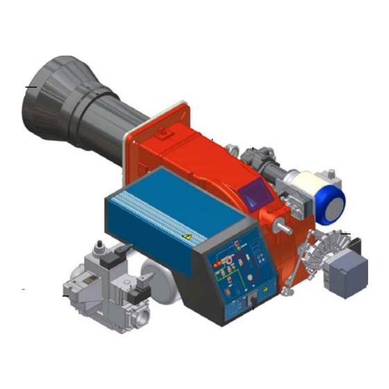
- Page 5 PART I: INSTALLATION GENERAL FEATURES This series represents monobloc gas burners made in die-cast aluminium housing, that can burn either gas or light oil, thanks to the adjustable combustion head which allows a good performance with both fuels. They can be provided in progressive or fully-modulating version.
- Page 6 Campo di lavoro bruciatori Tipo P60 Mod. M-xx.x.IT.A.0.50 - M-.xx.x.IT.A.0.65 Potenza kW Fig. 2 Data are referred to standard conditions: atmospheric pressure at 1013mbar, ambient temperature at 15°C Checking the proper gas train size To check the proper gas train size, it is necessary to know the available gas pressure value upstream the burner’s gas valve. Then sub- tract the backpressure.
- Page 7 Burner model identification Burners are identified by burner type and model. Burner model identification is described as follows. Type HP60 Model (1) BURNER TYPE HP60 (2) FUEL M - Natural gas G - Light oil B - Biogas (3) OPERATION (Available versions)
- Page 8 BURNER TYPE HP65 Output 270 - 970 min. - max. kW Nat. gas - Light oil Fuel Gas category see next paragraph 29 - 103 Gas rate min. - max. (Stm Gas pressure min. - max. mbar see Note 2 Light oil train inlet pressure max.
- Page 9 BURNER TYPE HP72...1.40 HP72...1.50 HP72...1.65 HP72...1.80 Output 330 - 1550 min. - max. kW Nat. gas - Light oil Fuel Gas category see next paragraph 35 - 164 Gas rate min. - max. (Stm see Note 2 Gas pressure min.- max. mbar Light oil train inlet pressure max.
- Page 10 Country and usefulness gas categories COUNTRY CATEGORY ES GR SE NO CZ DK GB CY EE MT SK BG RO TR CH 2E( R ) B (*) I 2ELL (*) Only for I : the appliance was configured for the appliance category K (I2K) and is suitable for the use of G and G+ distribution gases according to the specifications as included in the NTA 8837:2012 Annex D with a Wobbe index of 43.46 –...
- Page 11 Overall dimensions (mm) Boiler recommended drilling template...
- Page 12 O - min O - max 1119 HP60 MG..0.32 1153 362 1044 500 HP60 MG..0.40 1153 HP60 MG.. 0.50 1153 362 1115 685 HP60 MG.. 0.65 1156 139 382 1022 588 HP65 MG.. 0.32 1156 139 382 1148 714 HP65 MG.. 1.32...
- Page 13 Performance Curves HP60 HP65 HP72 MG..0... HP72 MG..1... HP73A ..1... To get the input in kcal/h, multiply value in kW by 860. Data are referred to standard conditions: atmospheric pressure at 1013mbar, ambient temperature at 15°C NOTE: The performance curve is a diagram that represents the burner performance in the type approval phase or in the laboratory tests, but does not represent the regulation range of the machine.
- Page 14 Pressure in the network - gas rate curves HP60 HP65 Gas rate Stm Gas rate Stm HP72...0.xx HP72...1.xx Gas rate Stm Gas rate Stm HP73A Rp 2" (50) DN65 DN80 Gas rate Stm Caution: the gas rate value is quoted on the x-axis, the related network pressure is quoted on the y-axis (pres- sure value in the combustion chamber is not included).
- Page 15 MOUNTINGS AND CONNECTIONS Packing Burners are despatched in cardboard packages and whose dimensions: 1280mm x 850mm x 760mm (L x P x H) Packing cases of this kind are affected by humidity and are not suitable for stacking. The following are placed in each packing case: burner with gas train detached;...
- Page 16 Gas train connections The next diagrams show the components of the gas train included in the delivery and which must be fitted by the installer.The diagrams are in compliance with the current laws. ATTENTION: BEFORE EXECUTING THE CONNECTIONS TO THE GAS PIPE NETWORK, BE SURE THAT THE MANUAL CUTOFF VALVES ARE CLOSED.
- Page 17 Assembling the gas grain gas supply network ”direction” arrows for installation Keys 1A..1E Gasket Gas filter Gas valves group Bellow joint Manual cock Fig. 5 - Example of gas train To mount the gas train, proceed as follows: 1-a) in case of threaded joints: use proper seals according to the gas used; 1-b) in case of flanged joints: place a gasket (no.
- Page 18 MULTIBLOC DUNGS MB-DLE 415..420 Mounting 1. Loosen screws A and B do not unscrew (Fig. 10 - Fig. 11). 2. unscrew screws C and D (Fig. 10 - Fig. 11). 3. Remove MultiBloc between the threaded flanges (Fig. 11). 4. After mounting, perform leakage and functional tests. MOUNTING POSITIONS Fig.
- Page 19 (spring) (cap) Fig. 17 Siemens VGD valves with SKP actuator: The pressure adjusting range, upstream the gas valves group, changes according to the spring provided with the valve group. 0 - 22 15 - 120 100 - 250 Performance range (mbar) neutral yellow Spring colour...
- Page 20 Hydraulic diagrams for light oil supplying circuits Fig. 18 - Gravity circuit Fig. 19 - Ring circuit Fig. 20 - Suction circuit Manual valve Light oil filter Light oil feeding pump One way valve Flexible hoses Relief valve NOTE: in plants where gravity or ring feed systems are provided, install an automatic interception device (see n. 4 - Fig. 21).
- Page 21 Light oil piping installation diagram From tank To tank Fig. 21 (*) Only for installations with gravity, siphon or for- ced circulation feed systems. If the device installed Burner is a solenoid valve, a timer must be installed to Flexible hoses (fitted) delay the valve closing.
- Page 22 An external filter should always be installed in the suction line upstream of the fuel unit. Light oil pumps The pumps provided with these burners can be: HP60 - HP65: Suntec AJ6 HP72: Suntec E7 HP73A : Suntec TA2 Suntec AJ6...
- Page 23 Suntec TA.. Oil viscosity 3 ÷ 75 cSt Oil temperature 0 ÷ 150°C Min. suction pressure - 0.45 bar to avoid gasing Max. suction pressure 5 bar Max. return pressure 5 bar Rotation speed 3600 rpm max. Inlet G1/2 To the nozzle G1/2 Return G1/2 Pressure gauge port G1/4 Vacuum gauge port G1/4...
- Page 24 Electrical connections WARNING! Respect the basic safety rules. make sure of the connection to the earthing system. do not reverse the phase and neutral connections. fit a differential thermal magnet switch adequate for connection to the mains. WARNING! before executing the electrical connections, pay attention to turn the plant’s switch to OFF and be sure that the burner’s main switch is in 0 position (OFF) too.
- Page 25 ADJUSTMENTS Combustion head gas pressure curves depending on the flow rate Curves are referred to pressure = 0mbar in the combustion head! The curves referred to the gas pressure in the combustion head, depending on the gas flow rate, are referred to the burner properly adjusted (percentage of residual O in the flues as shown in the “Recommended combustion values”...
- Page 26 Pressure in combustion head - gas rate curves HP60 HP65 Gas rate Stm Gas rate Stm HP72 HP73A Gas rate Stm Gas rate Stm WARNING: the diagrams refers to natural gas. For different type of fuel please refer to the paragraph “Fuel” at...
- Page 27 ATTENTION: before starting the burner up, be sure that the manual cutoff valves are open and check that the pres- sure upstream the gas train complies the value quoted on paragraph “Technical specifications”. Be sure that the mains switch is closed. .ATTENTION: During commissioning operations, do not let the burner operate with insufficient air flow (danger of formation of carbon monoxide);...
- Page 28 Actuator The actuator provided can be either berger STM30../Siemens SQM40.. (see page 29) or Siemens SQL33.. . IMPORTANT! the combustion air excess must be adjusted according to the in the following chart: Recommended combustion parameters Recommended (%) CO Recommended (%) O Fuel Natural gas 9 ÷...
- Page 29 Settings by means of Berger STM30../Siemens SQM40.. actuator Siemens SQM40 mensions Dimensions in Berger STM30 SQM4... Actuator cams (SQM40) High flame Stand-by Low flame - gas Low flame - oil Ignition - oil Ignition - gas Actuator cams (STM30) MAN-AUTO High flame Stand-by and Ignition Low flame - gas...
- Page 30 Note: once the procedure is perfomed, be sure that the blocking nut RA is fasten. Do not change the position of the air damper rods. 11 The burner is factory-set with the head in its MAX position (maximum output). To let the burner operate at a lower output, turn clockwise the VRT screw and move progressively the combustion head back towards the MIN position.
- Page 31 Calibration of air and gas pressure switches The air pressure switch locks the control box if the air pressure is not the one requested. If it happens, unlock the burner by means of the control box unlock pushbutton, placed on the burner control panel. The gas pressure switches check the pressure to avoid the burner operate when the pressure value is not in the requested pressure range.
- Page 32 Fully modulating burners To adjust the fully-modulating burners, use the CMF switch on the burner control panel (see next picture), instead of the TAB thermo- stat as described on the previous paragraphs about the progressive burners. Go on adjusting the burner as described before, paying attention to use the CMF switch intead of TAB.
- Page 33 Adjustment procedure for light oil operation The light oil flow rate can be adjusted choosing a by-pass nozzle that suits the boiler/utilisation output and setting the delivery and return pressure values according to the ones quoted on the table below and the diagram on Fig. 25 (as far as reading the pressure values, see next paragraphs).
- Page 34 Fig. 25 Example (Bergonzo): if a 220kg/h flow rate BERGONZO nozzle is provided, set the return pressure at 11bar, supply at 20bar on the delivery to get a 220kg/h flow rate. If the return pressure needed is 5bar, instead, act on the V adjusting screw on the pressure governor (see chapter on page 33).
- Page 35 Fig. 26 Example (Bergonzo): if a 140kg/h flow rate BERGONZO 45° nozzle is provided, set the return pressure at 13bar, supply at 20bar on the delivery to get a 110kg/h flow rate. If the return pressure needed is 5bar, instead, act on the adjusting screw on the pressure gover- nor.
- Page 36 Fig. 27...
- Page 37 FLUIDICS KW3...45° NOZZLE SUPPLY PRESSURE = 20 bar. VISCOSITY AT NOZZLE = 5 cSt The nominal size of the nozzle is indicated at the ends of the curve Pressure on return (bar) Pressure on return (bar) Pressure on return (bar)
- Page 38 FLUIDICS KW3...45° NOZZLE SUPPLY PRESSURE = 20 bar. VISCOSITY AT NOZZLE = 5 cSt The nominal size of the nozzle is indicated at the ends of the curve Pressure on return (bar) Pressure on return (bar) Pressure on return (bar)
- Page 39 FLUIDICS KW3...60° NOZZLE SUPPLY PRESSURE = 20 bar. VISCOSITY AT NOZZLE = 5 cSt The nominal size of the nozzle is indicated at the ends of the curve Pressure on return (bar)
- Page 40 FLUIDICS KW3...60° NOZZLE SUPPLY PRESSURE = 20 bar. VISCOSITY AT NOZZLE = 5 cSt The nominal size of the nozzle is indicated at the ends of the curve Pressure on return (bar) Pressure on return (bar)
- Page 41 Oil Flow Rate Settings by means of Berger STM30../Siemens SQM40.. actuator Once the air and gas flow rates are adjusted, turn the burner off, switch the CM switch to the heavy oil operation (OIL, on the bur- ner control panel (see page 45). with the electrical panel open, prime the oil pump acting directly on the related CP contactor (see next picture): check the pump motor rotation and keep pressing for some seconds until the oil circuit is charged;...
- Page 42 Fig. 28) as to get the nozzle pressure at 20bar (Monarch or Fluidics nozzles - see page 33-34). Pressure gauge port Fig. 29 Fig. 30 10 in order to get the maximum oil flow rate, adjust the pressure (reading its value on the PG pressure gauge) without changing the air flow rate set during the gas operation adjustments (see previous paragraph): checking always the combustion parameters, the adjustment is to be performed by means of the SV2 adjusting cam screw (see picture) when the cam has reached the high flame position.
- Page 43 Maximum oil pressure switch The oil pressure switch on the return line, checks that the pressure does not exceed a default value. This value must not be higher than the maximum acceptable pressure on the return line (this value is reported on the specification table). A pressure change on the return line could affect the combustion parameters: for this reason, the pressure switch must be set, say, at 20% over the pressure recorded during the combustion adjustment.
- Page 44 Oil circuit The fuel is pushed into the pump 1 to the nozzle 3 at the delivery pressure set by the pressure governor. The solenoid valve 2 stops the fuel immission into the combustion chamber. The fuel flow rate that is not burnt goes back to the tank through the return circuit. The spill-back nozzle is feeded at constant pressure, while the return line pressure is adjusted by means of the pressure governor controlled by an actuator coupled to an adjusting cam.
- Page 45 PART II: OPERATION LIMITATIONS OF USE THE BURNER IS AN APPLIANCE DESIGNED AND CONSTRUCTED TO OPERATE ONLY AFTER BEING CORRECTLY CONNEC- TED TO A HEAT GENERATOR (E.G. BOILER, HOT AIR GENERATOR, FURNACE, ETC.), ANY OTHER USE IS TO BE CONSIDE- RED IMPROPER AND THEREFORE DANGEROUS.
- Page 46 Few seconds after the gas valves opening, the transformer is de-energised and lamp L turns off. The burner is now operating, meanwhile the actuator goes to the high flame position and, after some seconds, the two-stage ope- ration begins; the burner is driven automatically to high flame or low flame, according to the plant requirements. Operation in high or low flame is signalled by lamp N on the frontal panel.
- Page 47 PART III: MAINTENANCE At least once a year carry out the maintenance operations listed below. In the case of seasonal servicing, it is recommended to carry out the maintenance at the end of each heating season; in the case of continuous operation the maintenance is carried out every 6 months.
- Page 48 Fig. 36 Fig. 35 Fig. 37 Removing the filter in the MULTIBLOC DUNGS MB-DLE 415 - 420 B01 1” 1/2 - 2” Check the filter at least once a year! Change the filter if the pressure difference between pressure connection 1 and 2 (Fig. 38-Fig. 39) Δp> 10 mbar. Change the filter if the pressure difference between pressure connection 1 and 2 (Fig.
- Page 49 Fig. 40 Gas filter maintenance ATTENTION: Before opening the filter, close the manual cutoff valve downstream the filter and bleed the gas; check that inside the filter there is no pressurised gas. To clean or remove the filter, proceed as follows: remove the cap unscrewing the fixing screws (A);...
- Page 50 Clean the combustion head by means of a vacuum cleaner; scrape off the scale by means of a metallic brush. Note: to replace the combustion head, reverse the operations described above. Adjusting the electrodes position Adjust the electrodes position, according to the quotes (in mm) shown on the next picture. HP60-65-72 Fig. 41 HP73A *8÷...
- Page 51 VE fixing screws and remove them: place the new electrodes being careful to observe the measures in the previous paragraph; reassemble the electrodes and the combustion head following the reversed procedure. HP60-65-72 HP73A...
- Page 52 Seasonal stop To stop the burner in the seasonal stop, proceed as follows: turn the burner main switch to 0 (Off position) disconnect the power mains close the fuel valve of the supply line Burner disposal In case of disposal, follow the instructions according to the laws in force in your country about the “Disposal of materials”.
- Page 53 TROUBLESHOOTING TROUBLE CAUSE MAIN SWITCH OPEN LACK OF GAS MAXIMUM GAS PRESSURE SWITCH DEFECTIVE (IF PROVIDED) THERMOSTATS/PRESSURE SWITCHES DEFECTIVE FAN MOTOR THERMAL CUTOUT INTERVENTION OVERLOAD TRIPPED INTERVENTION AUXILIARY FUSES INTERRUPTED CONTROL BOX FAULTY DEFECTIVE ACTUATOR AIR PRESSURE SWITCH FAULT OR BAD SETTING MINIMUM GAS PRESSURE SWITCH DEFECTIVE OR GAS FILTER DIRTY IGNITION TRANSFORMER FAULT...
- Page 54 BURNER EXPLODED VIEW DESCRIPTION DESCRIPTION ITEM ITEM FRONT CONTROL PANEL PRESSURE PLUG LIGHT ELBOW LIGHT THROTTLE SHAFT LOCK-OUT RESET BUTTON BUTTERFLY GAS VALVE PROTECTION PHOTOCELL SWITCH STANDARD BLAST TUBE BOARD AIR PRESSURE SWITCH COVER SCREW IGNITION ELECTRODE NOZZLE LEVERAGE IGNITION CABLE NOZZLE HOLDER JOINT GAS MANIFOLD...
- Page 56 WIRING DIAGRAMS Refer to the attached wiring diagrams. WARNING 1 - Electrical supply 230V / 400V 50Hz 3N a.c. 2 - Do not reverse phase with neutral 3 - Ensure burner is properly earthed...
- Page 60 C.I.B. UNIGAS S.p.A. Via L.Galvani, 9 - 35011 Campodarsego (PD) - ITALY Tel. +39 049 9200944 - Fax +39 049 9200945/9201269 web site: www.cibunigas.it - e-mail: cibunigas@cibunigas.it Note: specifications and data subject to change. Errors and omissions exceptd.
- Page 61 LME73.000Ax + PME73.831AxBC LME73.831AxBC Service instruction manual M12921CB Rel.1.2 02/2016...
- Page 62 GENERAL FEATURES LME/ is suitable for gas, light and heavy oil burners LME7 series has two devices: LME73.000 (hardware) and PME73.831AxBC (programmable unit). The LME73.831AxBC is also available: it has a built in software and it isa not programmable. LME7 is inside the control panel. If supplied, PME73.831BC is inside the LME7; The display AZL23..
- Page 63 User interface : Button A - Display preset output - In lockout position: Power value to the time of fault Info and Enter button - Reset in the event of fault, changeover visual diagnostic of the cause of fault (refer to chapter Diagnostics of cause of fault ) - button - Display flame signal current 2 or phases display - In lockout position: MMI phase to the time of fault...
- Page 64 List of phase display on board LME : Phase number of Function 7-segment display Standby Standby, waiting for heat demand Mains ON / test phase (e.g. detector test) Startup Yellow Safety valve ON, air pressure switch test / POC test (timeout / locking Yellow Fan motor ON / air pressure switch test / settling time Yellow...
- Page 65 Operation : The lockout reset button (info button) (EK) is the key operating element for resetting the burner control and for activating / deactivating the diagnostics functions. The multicolor signal lamp (LED) is the key indicating element for visual diagnostics. Both lockout reset button (EK) and signal lamp (LED) are located in the control panel.
- Page 66 Program sequence : Version 1: • Ignition load < low-fire • Prepurging in high-fire • Parameter 515 = 1 (condition parameter 259.01 > 0 seconds)
- Page 67 Program sequence : Version 2: • Ignition load > low-fire • Prepurging in high-fire • Parameter 515 = 1 (condition parameter 259.01 = 0 seconds)
- Page 68 Phase Function number Lockout phase Standby, waiting for heat demand Operation, modulating operation Interval until release of load controller target (analog or 3-position step input) Under voltage Safety loop open Extraneous light on burner startup (timeout/locking after 30 seconds) Mains ON/test phase (e.g. detector test) Shutdown, actuator opens in CLOSE position (homerun) Safety valve ON, air pressure switch OFF, actuator opens in CLOSE position Part 1: Fan motor ON...
- Page 69 Error code table : Red blink code of fault signal lamp (LED) Possible cause 2 x blinks No establishment of flame at the end of the safety time (TSA) - Faulty or soiled flame detector - Faulty or soiled fuel valves - Poor adjustment of burner, no fuel - Faulty ignition equipment 3 x blinks...
- Page 70 Flame detection – detection electrode : Short-circuit current Max. AC 1 mA Required detector current Min. DC 2 μA, display approx. 45 % Possible detector current Max. DC 3 μA, display approx. 100 % Permissible length of detector cable (laid separately) 30 m (core-earth 100 pF/m) Measuring circuit Keys...
- Page 71 Gas proving system : Valve proving is dependent on input valve proving ON / OFF (X2-02). When a leak is detected, the gas valve proving function ensures that the gas valves will not be opened and that ignition will not be switched on. Lockout will be initiated. Valve proving with separate pressure switch (P LT) Step 1: td4 –...
- Page 72 Instruction, control and modify via AZL2x : The AZL2x.. display/programming unit is shown below: The keys functions are the following: Key F + A While pressing the two keys contemporarly, the code message will appear: by entering the proper password it is possible to access the Service mode. Info and Enter keys Used for Info and Service menues Used as Enter key in the setting modes...
- Page 73 The display will show these data: Lock+unlock codes Flame Open valves Ignition transformers energised Fan motor energised Oil pre-heater energised Plant heat request Parameter setting mode Info mode Service mode Closing actuator Opening actuator Unit measure While pushing the button together with whatever else button, LME73 locks out; the display shows On stand-by position, appears On operation, all the phases appears with their number.
- Page 74 List of phase with display AZL2x : Phase number Function Standby Standby, waiting for heat request Ph08 Power ON / test phase (e.g. detector test) Startup Ph21 Safety valve ON, air pressure switch test / POC test (timeout / locking after 5 seconds), actuator opens in low-fire position / CLOSE position Ph22 Fan motor ON or air pressure switch test / settling time...
- Page 75 Error code list with operation via internal AZL : Error code Clear text Possible cause Loc 2 No establishment of flame at the - Faulty or soiled fuel valves end of the safety time (TSA) - Faulty or soiled flame detector - Poor adjustment of burner, no fuel - Faulty ignition equipment Loc 3...
- Page 76 Entering the Parameter levels: y means of a proper use of the keys, it is possible to enter the various level parameters, as shown in the following flow chart :...
- Page 77 Info level : Keep pushing the button until appears. Use + or - for scrolling the parameter list. If on the right side a dash-dot appears, it means the display doesn't show the full description. Push again for 1 to 3 s in order to show the full description. Below the visible Info parameters: Parameter Parameter list...
- Page 78 Service level : Keep pushing the button until appears. Use + or - for scrolling the parameter list. . If on the right side a dash-dot appears, it means the display doesn't show the full description. Push again for 1 to 3 s in order to show the full description. Below the visible Info parameters: Parameter Parameter list...
- Page 79 Process data Normalized speed Read only 100% 0.01 % Service Mains voltage Read only LME73.000A1: Service 175 V LME73.000A2: 350 V Flame intensity Read only 100% Service...
- Page 80 Parameter level (Heating engeneering) : This level lets the engineer to modify some burner parameters. It is protect with a 4 digit password (SO level) and a 5 digit password (OEM level) Password input : push F and A buttons together until the display shows "code" and 7 underlines. The left one flashes. By move the flashing underline until it is on the desired position and push "enter".
- Page 81 Repetition in the event of loss of flame during operation Edit 0 SO 0 = None 1 = None 2 = 1 x Repetition 241.00 Valve proving Edit 1 SO 0 = Off 1 = On 241.01 Valve proving Edit 0 SO 0 = During prepurge time (t1) 1 = During postpurge time (t8)
- Page 82 Power setting Analog input (feedback potentiometer ASZxx.3x required) Edit 0 SO 0 = 3-position step input 1 = 0...10 V 2 = 0...135 Ω 3 = 0...20 mA 4 = 4...20 mA with lockout at I <4 mA 5 = 4...20 mA WARNING Parameter Num.
- Page 84 Note: Specifications and data subject to change. Errors and omissions excepted.
Need help?
Do you have a question about the HP60 and is the answer not in the manual?
Questions and answers