Unigas HP60 Manual
Dual fuel gas and light oil burners
Hide thumbs
Also See for HP60:
- Manual of installation - use - maintenance (96 pages) ,
- Manual of installation - use - maintenance (88 pages) ,
- Manual of installation - use - maintenance (60 pages)
Advertisement
Quick Links
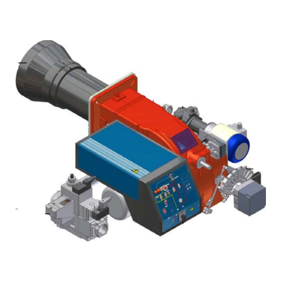
B U R N E R S
B R U L E U R S
B R E N N E R
QUEMADORES
B R U C I AT O R I
MANUAL OF
. INSTALLATION
. OPERATING
. MAINTENANCE
DUAL FUEL
GAS AND LIGHT OIL
BURNERS TYPE:
HP60
HP72
FOREWORD
PART I:
INSTALLATION
PART II:
OPERATIONS
PART III: MAINTENANCE
APPENDIX
M03957CA Rev.00 Ed.04/96
P. 2
P . 4
P . 18
P . 20
P . 26
1
Advertisement

Related Manuals for Unigas HP60


Summary of Contents for Unigas HP60
- Page 1 . MAINTENANCE B R E N N E R QUEMADORES B R U C I AT O R I DUAL FUEL GAS AND LIGHT OIL BURNERS TYPE: HP60 HP72 M03957CA Rev.00 Ed.04/96 FOREWORD P. 2 PART I: INSTALLATION P . 4...
- Page 2 NOTICES THIS MANUAL IS SUPPLIED AS AN INTEGRAL AND ESSENTIAL PART OF THE PRODUCT AND MUST BE DELIVERED TO THE USER. INFORMATION INCLUDED IN THIS SECTION ARE DEDICATED BOTH TO THE USER AND TO PERSONNEL FOLLOWING PRODUCT INSTALLATION AND MAINTENANCE. CAREFULLY KEEP THIS MANUAL FOR FUTURE REFERENCE.
- Page 3 to take the maximum power used by the equipment shown on the equipment Precautions if you can smell gas: rating plate. In particular, make sure that the system cable cross section is adequate for the power absorbed by the unit. a) do not operate electric switches, the telephone, or any other item likely to generate sparks;...
-
Page 4: Technical Data
PART 1: INSTALLATION MANUAL TECHNICAL DATA BURNER TYPE HP60 HP72 Input min. (gas) kW min. (oil) kW max. kW 1.550 min. (gas) kcal/h 146.200 283.800 min. (oil) kcal/h 215.000 352.600 max. kcal/h 756.800 1.333.000 Fuel Natural Gas - Light Oil... - Page 5 (6) SPECIAL VERSION A - Standard (7) BURNER EQUIPMENT - available options 0 - 2 Valves 1 - 2 Valves + Leak detection monitor (Optional on type HP60) (8) GAS TRAIN SIZE (See Technical Data; 40=Rp11/2; 50=Rp2; 65=DN65.) OVERALL DIMENSIONS IN mm...
-
Page 6: Performance Curves
PERFORMANCE CURVES HP60 Fig. 2 1000 INPUT kW HP72 Fig. 3 1000 1200 1400 1600 INPUT kW C.D.C. = COMBUSTION CHAMBER = lower limit of oil burner performance curve. INSTALLATION MANUAL... - Page 7 MOUNTINGS AND CONNECTIONS Packing The burners are despatched in cardboard packages of dimensions: HP72 1400 - 1190 - 710 mm ( “ “ “ Packing cases of this type are affected by humidity and are not suitable for stacking. The following are placed in each packing case: burner with gas train which is detached but already connected to the burner electrically ;...
- Page 8 INSTALLER LEGEND 1) Burner 2) Gas twin valve (including gas pressure switch) 3) Leak detection monitor (Optional on type HP60) 4) Gas governor and filter 5) Manually Operated Shutt-off Valve Size: see technical data - gas connection Fig. 6 SPECIAL REQUIREMENTS FOR APPLICATIONS ON STEAM BOILERS...
- Page 9 Ring system Key: 1) Manual interceptor valve 2) Gas filter 3) Light Oil feed pump 4) One way valve 5) Light Oil flexible tubing 6) Spillage valve Fig. 9 Suction system Monotube systen The burners leave the factory equipped for twin-tube feed. Fig.
- Page 10 ADJUSTMENT Double valve Dungs DMVDLE C - RP It is a single body valve assembly includung two class A electric gas valves. One of them is slow opening type. The valve assembly can be coupled with leakage control Dungs mod. VPS504. To set gas flow rate use screw RP, under cover C.
- Page 11 LANDIS gas valve Version with SPK10: no adjustment necessary. - Important: Do not remove the cover as oil may leak out. Version with SKP20: (with built in pressure stabiliser). - To increase or decrease gas pressure, and therefore gas flow, remove the cap and use a screwdriver to adjust the regulator screw VR.
- Page 12 To prime the pump Before starting to regulate for light oil operation it is necessary to prime the light oil pump using the following procedure: turn on the burner; when the electrovalve comes on switch on the light resistor and clear the air out of the manometer connection.
- Page 13 Key: 1) Oil pump 2) Min oil pressure switch 3) Oil electrovalve Fig. 19 4) Nozzle 5) Adjustable cam 6) Pressure regulator 7) Manometer 8) Max oil pressure switch Fig. 20 To regulate the delivery pressure adjust the pump regulator screw following the instructions given on page 14. See Appendix for further details about the light oil pump.
- Page 14 Oil pumps Suntec AJ6CC pump (for type HP60) Suction: max. 0,5 bars - maximum recommended depression to avoid formation of air bubbles: 0,35 mbars Velocity max. 3600 rpm Operational viscosity: 2,7-75 cSt Intake & back pressure: 2 bars Fig. 22...
- Page 15 ADJUSTMENT OF GAS AND AIR FLOW RATE NOTA BENE: During commissioning operations, do not let the burner function with insufficient air flow (danger of formation of carbon monoxide); if this should happen, shut down the burner, increase the opening of the air damper and start up the burner again to ensure the purging of the carbon monoxide from the combustion chamber.
- Page 16 Calibration of air pressure switch Calibration is carried out as follows: Remove the transparent plastic cap. After air and gas setting has been completed , start the burner and, while prepurge phase is running, slowly turn the adjusting ring nut VR in the clockwise direction until the burner lockout (on the Elbi pressure switch undo screw VB).
- Page 17 N.B. On burner type HP72 loosen the screw VB before adjusting and tighten it up again afterwards. COMBUSTION BURNER INPUT (kW) HEAD POSITION HP60 HP72 From From 450 - 880 850 - 1550 400 - 450...
-
Page 18: Limitations Of Use
PART II: OPERATIONS MANUAL LIMITATIONS OF USE THE BURNER IS AN APPLIANCE DESIGNED AND CONSTRUCTED TO OPERATE ONLY AFTER BEING CORRECTLY CONNECTED TO A HEAT GENERATOR (E.G. BOILER, HOT AIR GENERATOR, FURNACE, ETC.), ANY OTHER USE IS TO BE CONSIDERED IMPROPER AND THEREFORE DANGEROUS. THE USER MUST GUARANTEE THE CORRECT FITTING OF THE APPLIANCE, ENTRUSTING THE INSTALLATION OF IT TO QUALIFIED PERSONNEL AND HAVING THE FIRST COMMISSIONING OF IT CARRIED OUT BY A SERVICE CENTRE AUTHORISED BY THE COMPANY MANUFACTURING THE... - Page 19 Front panel Fig. 31 Key: A: Main on/off switch B: LED indicating burner blocked C: Re-set button for burner monitor D: LED indicating gas pressostat all-clear E: LED indicating valve gas-tight monitor blocked F: Reset button for valve gas-tight monitor (only for burners fitted with LANDIS LDU11 monitor. G: LED indicating high-flame operation H: LED indicating low-flame operation I: LED indicating ignition tramnsformer working...
-
Page 20: Periodical Servicing
- Clean and degrease joints and rotating parts. IMPORTANT: Remove the combustion head before checking the ignition electrodes. To remove the combustion head Type HP60 Remove the cap H. Slide the UV photoelectric cell out of its housing. - Page 21 Type HP72 Remove the cap H. Slide the UV photoelectric cell out of its housing. Undo the locking screws V holding the gas collector, loosen the two connectors E connecting the nozzle to the flexible tubing and remove the whole assembly as shown in Fig.33. Note: to replace the combustion head reverse the procedure described above.
-
Page 22: Fault Finding Table
TERMINAL BLOCK MC Terminal board Check of ionisation current To measure the detection signals follow the scheme in fig. If the signal is less than the value shown, check the position of the FLAME detection electrode, the electrical contacts and if µ... - Page 23 ELECTRICAL DIAGRAM (code 05-483 Rev.03) LEGEND cod. 05-483 rev.3 Pump motor remote contactor coil Fan motor remote contactor coil Pump motor auxiliary contacts contactor Manual operation switch 0) off 1) gas 2) light oil Pump motor contactor CR1/2 Relay contacts Pump motor overload contacts Fan motor contacts Fan motor contactor...
- Page 24 ELECTRICAL DIAGRAM (code 05-483 Rev.03) MAINTENANCE MANUAL...
- Page 25 MAINTENANCE MANUAL...
- Page 26 APPENDIX: COMPONENT CHARACTERISTICS Landis&Gyr LFL1.322 flame monitor Pag. 26-27-28 Dungs Multibloc twin valves Pag. 29 Dungs VPS504 leakage control Pag. 29 Suntec AJ6CC light oil pump Pag. 30 Suntec E7NC1001 light oil pump Pag. 31 Oil nozzle Pag. 32-33-34-35 LANDIS & GYR LFL 1,322 Automatic programme in the event of interruption and indication of position when interrupted In principle, in the event of any kind of response to start-up given by the thermostat or pressostat “R”...
- Page 27 feed a fuel valve at auxiliary contact “V” of the damper servomotor. Weight: Interval At the end of t5 terminal 20 is live. At the same time the apparatus c.1,000g. monitor outlets from 9 and 11 and terminal 8 into the active part of base c.165g.
- Page 28 Key: limit contact switch for damper OPEN position advance signal of a block main relay (working network) with contacts “ar” Monitor fuse block relay with “br” contacts fuel valve reset button detector electrode of ionisation circuit flame relay with “fr” contacts ventilator motor or burner motor gas pressostat main interruptor switch...
- Page 29 DOUBLE ELECTROMAGNETIC VALVES DMV-DLE/11 Absorbed power: during pumping time: approx.15-20 VA Technical data in service: SVA Flange dimensions DN40/50/65/80/100/125 Max. working pressure 500mbars(50kPa) Fuse at inlet 10 A rapid or 6A T Phase pressure Electromagnetic valve V1 automatic lock valve Interchangeable fuse standard EN161 Class A, Group 2...
- Page 30 SUNTEC AJ6CC LIGHT OIL PUMP Applications Operation The gear assembly sucks in the oil through the filter and Light Oil - flow up to 150 1/h - Normally used with on-line transfers it under pressure to the valve. When the spring electromagnetic valve reaches the calibrated figure the oil pressure forces the piston head back allowing the oil to pass along the line to the nozzle.
- Page 31 E7NC1001 Light Oil pump Hydraulic data Working pressure 14-30 bars Factory calibration 14 bars Applications Viscosity 2,8- 800 cSt Light Oil Max.0il temperature 90_C Flow up to 300 1/h Flow 60- 3001/h Normally used with a on-line electromagnetic valve Back pressure max.3,5 mbars Twin-tube system Suction...
- Page 32 MONARCH OIL NOZZLE Mod. F80-BPS APPENDIX...
- Page 33 BERGNZO OIL ZOZZLE Mod. A3 APPENDIX...
- Page 34 FLUIDICS OIL NOZZLE Mod. K3 APPENDIX...
- Page 35 FLUIDICS OIL NOZZLE Mod. KC2 APPENDIX...
- Page 36 CIB UNIGAS S.p.A. Via Pioga, 27 (Zona Industriale) 35011 CAMPODARSEGO (Padova) Italy Tel. 049/9200944 - Telefax 049/9200945 - 9201269...
Need help?
Do you have a question about the HP60 and is the answer not in the manual?
Questions and answers