Table of Contents

Related Manuals for Unigas HP91A


Summary of Contents for Unigas HP91A
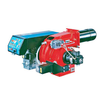
- Page 1 HP91A-HP92A-HP93A HP512A-HP515A HP520A-HP525A Progressive and fully-modulating gas - light oil burners MANUAL OF INSTALLATION - USE - MAINTENANCE BURNERS - BRUCIATORI - BRULERS - BRENNER - QUEMADORES - ГОРЕЛКИ M039140CE Rev. 4 12/2009...
-
Page 2: General Introduction
DANGERS, WARNINGS AND NOTES OF CAUTION THIS MANUAL IS SUPPLIED AS AN INTEGRAL AND ESSENTIAL PART OF THE PRODUCT AND MUST BE DELIVERED TO THE USER. INFORMATION INCLUDED IN THIS SECTION ARE DEDICATED BOTH TO THE USER AND TO PERSONNEL FOLLOWING PRODUCT INSTALLATION AND MAINTENANCE. -
Page 3: Directives And Standards
3b) FIRING WITH GAS, LIGHT OIL OR OTHER FUELS DIRECTIVES AND STANDARDS Gas burners GENERAL European directives The burner shall be installed by qualified personnel and in compliance -Regulation 2016/426/UE (appliances burning gaseous fuels) with regulations and provisions in force; wrong installation can cause -2014/35/UE (Low Tension Directive) injuries to people and animals, or damage to property, for which the -2014/30/UE (Electromagnetic compatibility Directive) -
Page 4: Symbols Used
Burner data plate Type Gas - Light oil burners For the following information, please refer to Model Year European Directives the data plate: S.Number -Regulation 2016/426/UE (appliances burning gaseous fuels) burner type and burner model: must be Output Oil Flow -2014/35/UE (Low Tension Directive) reported in any communication with the Fuel... -
Page 5: General Features
C.I.B. UNIGAS - M039140CE PART I: INSTALLATION GENERAL FEATURES This series represents monobloc gas burners made in die-cast aluminium housing, that can burn either gas or light oil, thanks to the adjustable combustion head which allows a good performance with both fuels. They can be provided in progressive or fully-modulating version. -
Page 6: Burner Model Identification
C.I.B. UNIGAS - M039140CE How to interpret the burner “Performance curve” To check if the burner is suitable for the boiler to which it must be installled, the following parameters are needed: furnace input, in kW or kcal/h (kW = kcal/h / 860);... -
Page 7: Specifications
C.I.B. UNIGAS - M039140CE Specifications BURNER TYPE HP91A HP92A HP93A HP512A Output min. - max. kW 480 - 2670 480 - 3050 550 - 4100 600 - 4500 Natural gas - Light oil Fuel (see next paragraph) Category min.- max. (Stm... - Page 8 Overall dimensions (mm) HP91A - HP92A - HP93A Burner flange Boiler recommended drilling template Omin Omax HP91A 1455 1439 HP91A 1455 1544 HP91A 1455 1546 HP91A 1455 1636 1049 HP92A 1455 1439 HP92A 1455 1544 HP92A 1455 1546 HP92A 1455...
- Page 9 HP512A - HP515A - HP520A - HP525A Burner flange Boiler recommended drilling template HP512A 1608 1021 1595 HP512A 1608 1021 1614 HP512A 1608 1021 1616 HP512A 1608 1021 1706 1049 HP515A 1608 1021 1615 HP515A 1608 1021 1634 HP515A 1608 1021 1636 HP515A...
- Page 10 C.I.B. UNIGAS - M039140CE Performance Curves HP91A HP92A 1200 1600 2000 2400 2800 3200 1200 1600 2000 2400 2800 HP93A HP512A 500 1000 1500 2000 2500 3000 3500 4000 4500 1500 2500 3500 4500 HP515A HP520A 1500 2500 3500 4500...
- Page 11 C.I.B. UNIGAS - M039140CE Pressure in the network - gas rate curves HP91A HP92A Rp 2 (50) Rp 2 (50) DN65 DN65 DN80 DN80 DN100 DN100 HP93A HP512A Rp 2 (50) Rp 2 (50) DN65 DN65 DN80 DN80 DN100 DN100...
- Page 12 C.I.B. UNIGAS - M039140CE MOUNTINGS AND CONNECTIONS Packing The burners are despatched wooden cages whose dimensions: 9xA series: 1730mm x 1280mm x 1020mm (L x P x H) 5xxA series: 1730mm x 1430mm x 1130mm (L x P x H) Packing cases of this kind are affected by humidity and are not suitable for stacking.
- Page 13 C.I.B. UNIGAS - M039140CE SIDE UP SIDE DOWN Matching the burner to the boiler The burners described in this manual have been tested with combustion chambers that comply with EN676 regulation and whose dimensions are described in the diagram . In case the burner must be coupled with boilers with a combustion chamber smaller in dia- meter or shorter than those described in the diagram, please contact the supplier, to verify that a correct matching is possible, with res- pect of the application involved.
- Page 14 C.I.B. UNIGAS - M039140CE Gas train connections The diagrams show the components of the gas train included in the delivery and which must be fitted by the installer.The diagrams are in compliance with the current laws. ATTENTION: BEFORE EXECUTING THE CONNECTIONS TO THE GAS PIPE NETWORK, BE SURE THAT THE MANUAL CUTOFF VALVES ARE CLOSED.
- Page 15 C.I.B. UNIGAS - M039140CE Assembling the gas grain gas supply network ”direction” arrows for installation Keys 1A..1E Gasket Gas filter Gas valves group Bellows unit Manual valve Fig. 5 - Example of gas train To mount the gas train, proceed as follows: 1-a) in case of threaded joints: use proper seals according to the gas used;...
- Page 16 C.I.B. UNIGAS - M039140CE MULTIBLOCDUNGS MBC1900-3100-5000SE (Flanged valves group) Mounting 1. Insert setscrews A 2. Insert seals 3. Insert setscrews B 4. Tighten setscrews A + B. Ensure correct seating of the seal! 6. After installation, perform leakage and functional test.
- Page 17 C.I.B. UNIGAS - M039140CE Pressure adjusting range The pressure adjusting range, downstream the gas valves group, changes according to the spring provided with the valve group. DUNGS MBC..SE Siemens SKP actuator Keys 1 spring 2 cap DUNGS MBC valves: Performance range (mbar)
- Page 18 C.I.B. UNIGAS - M039140CE Hydraulic diagrams for light oil supplying circuits Fig. 13 - Gravity circuit Fig. 14 - Ring circuit Fig. 15 - Suction circuit Manual valve Light oil filter Light oil feeding pump One way valve Flexible hoses Relief valve NOTE: in plants where gravity or ring feed systems are provided, install an automatic interception device (see n.
- Page 19 C.I.B. UNIGAS - M039140CE Light oil piping installation diagram From tank To tank Fig. 16 (*) Only for installations with gravity, siphon or for- ced circulation feed systems. If the device installed Burner is a solenoid valve, a timer must be installed to Flexible hoses (fitted) delay the valve closing.
- Page 20 C.I.B. UNIGAS - M039140CE Pipes should not contain air pockets. Rapid attachment joint should therefore be avoided and threaded or mechanical seal junc- tions preferred. Junction threads, elbow joints and couplings should be sealed with removable sg component. The number of junc- tions should be kept to a minimum as they are a possible source of leakage.
-
Page 21: Electrical Connections
C.I.B. UNIGAS - M039140CE Pressure regulator valve Suntec TV Pressure regulation Remove cap-nut 1 and the gasket 2, unscrew the lock nut 4. To increase pressure, turn adjusting screw 3 clockwise. To decrease the pressure, turn screw anticlockwise. Tight the lock nut 4, refit the gasket 2 and the cap nut 1. - Page 22 C.I.B. UNIGAS - M039140CE Electrical Wiring Diagram for Burners Fitted with Printed Circuit High-low flame burners Electric motor connection Probes connection Fully modulating burners RWF40 >>> Power supply terminal board Terminal board for connections on printed circuit Rotation of fan motor and pump motor Once the electrical connection of the burner is executed, remember to check the rotation of the motor.
- Page 23 C.I.B. UNIGAS - M039140CE Connecting burners not fitted with printed circuit High-low flame burners Probes connection Fully modulating burners Fig. 17 (**) Probes connection (Fig. 17) ADJUSTMENTS Combustion head gas pressure curves depending on the flow rate Curves are referred to pressure = 0mbar in the combustion head!
- Page 24 C.I.B. UNIGAS - M039140CE Measuring the gas pressure in the combustion head In order to measure the pressure in the combustion head, insert the pressure gauge probes: one into the combustion chamber’s pres- sure outlet (Fig. 18-2) to get the pressure in the combustion chamber and the other one into the butterfly valve’s pressure outlet of the burner (Fig.
-
Page 25: Gas Filter
C.I.B. UNIGAS - M039140CE Adjustments ATTENTION: before starting the burner up, be sure that the manual cutoff valves are open and check that the pres- sure upstream the gas train complies the value quoted on paragraph “Technical specifications”. Be sure that the mains switch is closed. -
Page 26: Adjustment Procedure
V screws that fix the adjusting plate D; insert a screwdriver on the adjusting plate notches and let it move CW/CCW as to open/close the holes; once the adjustmet is performed, fasten the V screws. HP91A - HP92A - HP93A open holes closed holes... - Page 27 C.I.B. UNIGAS - M039140CE Air and Gas Flow Rate Settings by means of Berger STM30.. / Siemens SQM40.. actuator set GAS fuel by means of the burner CM switch (it is placed on the burner control panel - see Fig. 32) check the fan motor rotation (see page 22).
- Page 28 C.I.B. UNIGAS - M039140CE “MAX” head position ”MIN” head position Attention! if it is necessary to change the head position, repeat the air and gas adjustments described above. 11 the air and gas rate are now adjusted at the maximum power stage, go on with the point to point adjustement on the SV1 (gas side) adjusting cam as to reach the minimum output point.
- Page 29 C.I.B. UNIGAS - M039140CE Siemens VGD.. Dungs MBC..SE To adjust the air flow rate in the high flame stage, loose the RA nut and screw VRA as to get the desired air flow rate: moving the rod TR towards the air damper shaft, the air damper opens and consequently the air flow rate increases, moving it far from the shaft the air damper closes and the air flow rate decreases.
- Page 30 C.I.B. UNIGAS - M039140CE BF1 cam. 19 The low flame position must never match the ignition position that is why cam BF1 must be set 20°- 30° more than the ignition posi- tion (see ID1 index on previous pictures). Now adjust the pressure switches (see next paragraph).
- Page 31 C.I.B. UNIGAS - M039140CE The CMF position sets the oprating stages: to drive the burner to the high-flame stage, set CMF=1; to drive it to the low-flame stage, set CMF=2. To move the adjusting cam set CMF=1 or 2 and then CMF=0.
- Page 32 C.I.B. UNIGAS - M039140CE Adjusting light oil flow rate The light oil flow rate can be adjusted choosing a by-pass nozzle that suits the boiler/utilisation output and setting the delivery and return pressure values according to the ones quoted on the chart below and the diagram on Fig. 21-Fig. 22 (as far as reading the pres- sure values, see next paragraphs).
- Page 33 C.I.B. UNIGAS - M039140CE Tab. 1 Fig. 22 FLOW RATE kg/h Pressure at nozzle 25bar DIMENSIONS Pressure at nozzle 357psi Atomisation angle Pressure on return Pressure on return Up to 100kg/hUp Over 100kg/hOver % Flow rate% Flow rate ---------------Atomisation angle according to the return pressure...
- Page 34 C.I.B. UNIGAS - M039140CE Oil Flow Rate Settings by means of Berger STM30.. / Siemens SQM40.. actuator Once the air and gas flow rates are adjusted, turn the burner off, switch it on again by turning the CM switch to the oil operation (OIL, on the burner control panel (see page 39).
- Page 35 C.I.B. UNIGAS - M039140CE dics nozzles - see page 45-30). Pressure gauge port Fig. 24 Fig. 25 10 in order to get the maximum oil flow rate, adjust the pressure (reading its value on the PG pressure gauge) without changing the air flow rate set during the gas operation adjustments (see previous paragraph): checking always the combustion parameters, the adjustment is to be performed by means of the SV2 adjusting cam screw (see picture) when the cam has reached the high flame position.
- Page 36 C.I.B. UNIGAS - M039140CE The nozzle supply pressureis already factory-set and must not be changed. Only if necessary, adjust the supply pressure as follows (see related paragraph);insert a pressure gauge into the port shown on Fig. 25 and act on on the pump adjusting screw VR (see Fig.
-
Page 37: Oil Circuit
C.I.B. UNIGAS - M039140CE Oil circuit The fuel is pushed into the pump 1 to the nozzle 3 at the delivery pressure set by the pressure governor. The solenoid valve 2 stops the fuel immission into the combustion chamber. The fuel flow rate that is not burnt goes back to the tank through the return circuit. The spill-back nozzle is feeded at constant pressure, while the return line pressure is adjusted by means of the pressure governor controlled by an actuator coupled to an adjusting cam. - Page 38 C.I.B. UNIGAS - M039140CE PART II: OPERATION LIMITATIONS OF USE THE BURNER IS AN APPLIANCE DESIGNED AND CONSTRUCTED TO OPERATE ONLY AFTER BEING CORRECTLY CON- NECTED TO A HEAT GENERATOR (E.G. BOILER, HOT AIR GENERATOR, FURNACE, ETC.), ANY OTHER USE IS TO BE CONSI- DERED IMPROPER AND THEREFORE DANGEROUS.
-
Page 39: Gas Operation
C.I.B. UNIGAS - M039140CE OPERATION ATTENTION: before starting the burner up, be sure that the manual cutoff valves are open and check that the pressure upstream the gas train complies the value quoted on paragraph “Technical specifications”. Read care- fully the “WARNINGS” chapter in this manual. - Page 40 C.I.B. UNIGAS - M039140CE Fig. 32 - Burner control panel Keys Main switch and fuel selector CM (0=Off, 1=GAS, 2=OIL) CMF switch (0=stop, 1=low flame, 2=high flame, 3=automatic) - fully modulating burners only Control box reset pushbutton Gas proving system reset pushbutton (only for burners with Siemens LDU11 provided)
-
Page 41: Routine Maintenance
C.I.B. UNIGAS - M039140CE PART III: MAINTENANCE At least once a year carry out the maintenance operations listed below. In the case of seasonal servicing, it is recommended to carry out the maintenance at the end of each heating season; in the case of continuous operation the maintenance is carried out every 6 months. - Page 42 C.I.B. UNIGAS - M039140CE Inspection and replacement of the MULTIBLOC DUNGS MBC..SE filter (Threaded valves group) Inspect the filter at least once a year. Change the filter, if pressure value between pressure connections 1 and 2 is grea- ther than 10 mbar.
- Page 43 C.I.B. UNIGAS - M039140CE Adjusting the electrodes position Adjust the electrodes position, according to the quotes shown on the next picture. Keys electrodes air pipe ignition gas pipe nozzle Fig. 34 Cleaning and replacing the detection probe The photocell working life is about 10000 working hours (about 1 year), at max 50°C after which it must be replaced.
-
Page 44: Burner Exploded View
BURNER EXPLODED VIEW DESCRIPTION DESCRIPTION DESCRIPTION ITEM ITEM ITEM AIR INLET CONE 13.10.5 ACTUATOR SHAFT 20.7 STANDARD COMBUSTION HEAD BURNER HOUSING 14.1 BRACKET 20.8 IGNITION ELECTRODE COVER 14.2 BRACKET 20.9 IGNITION CABLE GENERATOR GASKET 14.3 MOTOR 20.10 STANDARD COMPLETE OIL GUN AIR PRESSURE SWITCH PIPE 14.4 COUPLING... -
Page 46: Spare Parts
C.I.B. UNIGAS - M039140CE SPARE PARTS Desription Code HP91A HP92A HP93A CONTROL BOX 2020448 2020448 2020448 IGNITION ELECTRODE 2080292 2080292 2080292 OIL FILTER 2090018 2090018 2090018 GAS FILTER - Rp 2 2090119 2090119 2090119 GAS FILTER - DN65 2090117 2090117... - Page 47 C.I.B. UNIGAS - M039140CE Desription Code HP512A HP515A HP520A HP525A CONTROL BOX 2020448 2020448 2020448 2020448 IGNITION ELECTRODE 2080292 2080292 2080292 2080292 OIL FILTER 2090018 2090018 2090018 2090018 GAS FILTER - Rp 2 2090119 2090119 2090119 2090119 GAS FILTER - DN65...
-
Page 48: Troubleshooting
TROUBLESHOOTING TROUBLE CAUSE MAIN SWITCH OPEN LACK OF GAS MAXIMUM GAS PRESSURE SWITCH DEFECTIVE (IF PROVIDED) THERMOSTATS/PRESSURE SWITCHES DEFECTIVE FAN MOTOR THERMAL CUTOUT INTERVENTION OVERLOAD TRIPPED INTERVENTION AUXILIARY FUSES INTERRUPTED CONTROL BOX FAULTY DEFECTIVE ACTUATOR AIR PRESSURE SWITCH FAULT OR BAD SETTING MINIMUM GAS PRESSURE SWITCH DEFECTIVE OR GAS FILTER DIRTY IGNITION TRANSFORMER FAULT... - Page 49 APPENDIX consent to start-up by means of the thermostat or pressostat "R" SIEMENS LFL 1.3.. CONTROL BOX start-up program Automatic programme in the event of interruption and indication of posi- normal burner operation tion when interrupted regulation stop caused by "R" By default, in the event of any kind of interruption, the flow of fuel is imme- diately interrupted.
- Page 50 2nd safety time; at the end of the second safety time the main bur- test 1300 µA ner should be lit by means of the pilot. At the end of this period, terminal Max.length of connecting cable 17 is dead and therefore the pilot burner will be out. normal cable (laid separately**) 100m Interval;...
- Page 51 interval for creating current between terminals 19 and 20 input for raising QRA detector voltage to test level post-ventilation time input for excitation of flame relay during flame detector test interval between startup consent and current created at circuit (contact XIV) and during safety time (contact IV) terminal 7 Do not press EK for more than 10 seconds duration of start-up...
- Page 52 C.I.B. UNIGAS S.p.A. Via L.Galvani, 9 - 35011 Campodarsego (PD) - ITALY Tel. +39 049 9200944 - Fax +39 049 9200945/9201269 web site: www.cibunigas.it - e-mail: cibunigas@cibunigas.it Note: specifications and data subject to change. Errors and omissions exceptd.
- Page 53 WIRING DIAGRAMS E039140CA Rev. 0 12/2009...
- Page 54 WIRING DIAGRAMS ATTENTION: 1- Power supply 400V 50 Hz, 3N a.c. 2- Don’t reverse phase with neutral 3- Ensure burner is properly hearted WIRING DIAGRAM .Cod. 21-019 WIRING DIAGRAMHP525 MG.PR..Cod. 11-336/1 - Progressive burners WIRING DIAGRAM HP525 MG.MD.. Cod. 11-339/1 - Fully modulating burners...
Need help?
Do you have a question about the HP91A and is the answer not in the manual?
Questions and answers