Hydac ContaminationSensor CS1000 Series Getting Started Manual
Hide thumbs
Also See for ContaminationSensor CS1000 Series:
- Operating and maintenance instructions manual (78 pages) ,
- Operation and maintenance instructions (136 pages) ,
- Operating and maintenance instructions manual (133 pages)
Table of Contents
Advertisement
Available languages
Available languages
Quick Links
Advertisement
Chapters
Table of Contents

Related Manuals for Hydac ContaminationSensor CS1000 Series


Summary of Contents for Hydac ContaminationSensor CS1000 Series
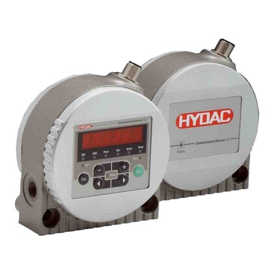
- Page 1 ContaminationSensor CS1000 Serie CS1000 Series CS1000 Série Kurzanleitung Beachten Sie die Betriebsanleitung. <Platzhalter> Titelbild Kurzanleitung “Getting Started” Guide Notice succincte 3538713b / 2023-04...
- Page 2 Originalanleitung © 2023 HYDAC Filter Systems GmbH. Alle Rechte vorbehalten. ® Alle verwendeten Produktnamen können Marken oder eingetragene Marken von HYDAC oder dem jeweiligen Eigentümer sein. Diese Anleitung haben wir nach bestem Wissen und Gewissen erstellt. Es ist dennoch nicht auszuschließen, dass sich trotz größter Sorgfalt Fehler eingeschlichen haben könnten.
-
Page 3: Table Of Contents
INHALTSVERZEICHNIS Inhaltsverzeichnis Lieferumfang prüfen ......................Technische Daten ......................Abmessungen ......................... Bestandteile ........................Transport und Lagerung....................Montage, Installation und Inbetriebnahme ..............Display drehen (nur CS1x2x) ................Sensor montieren / befestigen................Hydraulisch anschließen ..................6.3.1 Gewindeanschluss (nur CS1xxx-x-x-x-x-0) .......... 6.3.2 Flanschanschluss (nur CS1xxx-x-x-x-x-1)..........6.3.3 Messstelle im Hydrauliksystem finden.......... -
Page 4: Lieferumfang Prüfen
1. LIEFERUMFANG PRÜFEN Lieferumfang prüfen 490570379-1 Hier finden Sie den Lieferumfang rund um das Produkt. ● Prüfen Sie die Verpackung und das Produkt auf Beschädigungen. Melden Sie eventuell vorhandene Transportschäden dem Transportunternehmen bzw. der verantwortlichen Stelle. ● Prüfen Sie den Lieferumfang auf Vollständigkeit. Zum Lieferumfang gehören: Stück Bezeichnung... -
Page 5: Technische Daten
2. TECHNISCHE DATEN Technische Daten 490852875-1 Sind Ihnen die technischen Daten des Produkts bekannt, können Sie dieses optimal einsetzen. In diesem Kapitel finden Sie die technischen Daten zum Produkt: Allgemeine Daten Einbaulage Beliebig (Empfehlung: vertikal) Strömungsrichtung Beliebig Selbstdiagnose kontinuierlich mit Fehleranzeige über Sta- tus LED und Display Display (nur CS1x2x) LED, 6-stellig, mit je 17 Segmenten... - Page 6 (maximale Bürde 330 Ω) oder 2 … 10 V aktiver Ausgang (minimaler Lastwiderstand 820 Ω) Schaltausgang passiv, n-schaltender Power MOSFET: Schaltstrom ≤ 2 A, Schaltspannung ≤ 30 V DC, stromlos offen RS485 Schnittstelle 2-Draht, halbduplex HSI (HYDAC Sensor Interface) 1-Draht, halbduplex Tab. 4: Technische Daten – Elektrische Daten 6 / 64 3538713b / 2023-04...
-
Page 7: Abmessungen
3. ABMESSUNGEN Abmessungen 490645899-1 Der ContaminationSensor hat folgende Abmessungen: Abb. 1: Abmessungen CS1x2x mit Display (Alle Angaben in mm). Abb. 2: Abmessungen CS1x1x (Alle Angaben in mm) Abb. 3: Abmessungen Bohrbild (Alle Angaben in mm) 7 / 64 3538713b / 2023-04... -
Page 8: Bestandteile
4. BESTANDTEILE Bestandteile 492837131-1 Am ContaminationSensor finden Sie folgende Bestand- und Bedienteile. Abb. 4: Bestand- und Bedienteile 1 Sensorgehäuse mit Befestigungsbohrungen 2 Stecker 8-polig für: - Versorgungsspannung - Schnittstelle Analog / Digital - Schaltausgang 3 Vorderer Deckel, nur bei CS1x2x mit Display drehbar um 270° 4 Hinterer Deckel 5 Hydraulischer Anschluss 6 Hydraulischer Anschluss... -
Page 9: Transport Und Lagerung
5. TRANSPORT UND LAGERUNG Transport und Lagerung 490657803-1 Um Schäden am Produkt während des Transports oder des Lagerns zu vermeiden, fin- den Sie in diesem Kapitel entsprechende Hinweise. Der ContaminationSensor lässt sich in der Hand tragen. Vermeiden Sie dabei Druck auf das Display auszuüben. -
Page 10: Montage, Installation Und Inbetriebnahme
6. MONTAGE, INSTALLATION UND INBETRIEBNAHME Montage, Installation und Inbetriebnahme 490655499-1 Ein optimal montiertes und installiertes Produkt gewährleistet einen sicheren und dauer- haften Betrieb. In diesem Kapitel finden Sie Hinweise zur Befestigung, hydraulischen und elektrischen Installation mit abschließender Inbetriebnahme. Display drehen (nur CS1x2x) 490724747-1 Das Display ist stufenlos um insgesamt 270°... - Page 11 6. MONTAGE, INSTALLATION UND INBETRIEBNAHME Montage auf eine Konsole Mit vier Zylinderschrauben mit Innensechskant M6 gemäß ISO 4762 auf eine Konsole montieren. Abb. 6: Montage auf eine Konsole Montage auf eine Anschlussplatte / Flanschanschluss Mit vier Zylinderschrauben mit Innensechskant M6 gemäß ISO 4762 auf eine Montage- Anschluss- platte oder Steuer- oder Ventilblock montieren.
-
Page 12: Hydraulisch Anschließen
6. MONTAGE, INSTALLATION UND INBETRIEBNAHME Hydraulisch anschließen 490716555-1 Bestimmen Sie den Betriebsdruck des Hydrauliksystems so, dass der zuläs- sige Druck und Durchfluss am Eingang des ContaminationSensor erreicht wird. Verwenden Sie einen Anschluss A / C als Eintritt INLET und B / D als Austritt OUTLET. -
Page 13: Messstelle Im Hydrauliksystem Finden
6. MONTAGE, INSTALLATION UND INBETRIEBNAHME 6.3.3 Messstelle im Hydrauliksystem finden 492536203-1 Um kontinuierliche und zeitnah stimmige Reinheitswerte zu erhalten, wählen Sie die passende Messstelle sorgfältig nach folgenden Richtlinien aus: Falsch Falsch Abb. 9: Messstelle im Hydrauliksystem finden Wählen Sie den Messpunkt so, dass das Messvolumen aus einer turbulenten, gut durchströmten Umgebung kommt. -
Page 14: Durchfluss, Differenzdruck Und Viskosität Charakteristik
6. MONTAGE, INSTALLATION UND INBETRIEBNAHME 6.3.4 Durchfluss, Differenzdruck und Viskosität Charakteristik 492540427-1 Der Durchfluss Q ist abhängig von der Druckdifferenz Δp und der Viskosität η des Mediums. Die Diagramme zeigen die Abhängigkeit von Druckdifferenz Δp und der Viskosität η Charakteristik bei unterschiedlichem Volumenstrom Q. Alle dargestellten Werte in den Diagrammen gelten unabhängig von der Durchflussrichtung A->B oder B->A. -
Page 15: Sensor Hydraulisch Verbinden
6. MONTAGE, INSTALLATION UND INBETRIEBNAHME 6.3.5 Sensor hydraulisch verbinden 492639243-1 Beachten Sie zum Anschluss des ContaminationSensors an das Hydrauliksystem die folgende Reihenfolge: 1. Verbinden Sie die Rücklaufleitung mit dem Austritt des ContaminationSensors. Empfohlener Durchmesser der Leitung ≥ 4 mm. 2. Verbinden Sie das andere Ende der Rücklaufleitung zum Beispiel mit dem System- tank. -
Page 16: Anschlusskabel / Verbindungskabel - Farbcodierung
1 Spannungsversorgung 9 … 36 V DC 2 Analogausgang + (aktiv) 3 GND Spannungsversorgung 4 GND Analog- / Schaltausgang 5 HSI (HYDAC Sensor Interface) 6 RS485 + 7 RS485 - 8 Schaltausgang (passiv, Öffner) Der Analogausgang ist eine aktive Quelle von 4 … 20 mA oder 2 … 10 V DC. -
Page 17: Anschlussbeispiele
6. MONTAGE, INSTALLATION UND INBETRIEBNAHME 6.4.2 Anschlussbeispiele 492759563-1 Hier finden Sie Anschlussbeispiele: 1 weiss Schirm 3 grün Konverter 6 rosa RS485+ RS485 7 blau RS485- 5 grau 2 braun 4 gelb 8 rot Schirm Abb. 11: Schaltbild mit einer Spannungsversorgung (z. B. 24 V DC) 1 weiss Schirm 3 grün... -
Page 18: Inbetriebnahme
6. MONTAGE, INSTALLATION UND INBETRIEBNAHME Inbetriebnahme 490880267-1 Zur Inbetriebnahme gehen Sie wie folgt vor: ü Der ContaminationSensor ist, wie in den Kapiteln zuvor beschrieben, hydraulisch angeschlossen. ü Der ContaminationSensor ist, wie in den Kapiteln zuvor beschrieben, elektrisch ver- bunden bzw. mit einer Spannungsquelle verbunden. 1. -
Page 19: Betrieb
Display ablesen / Tastatur bedienen (nur CS1x2x) 492845195-1 Wird der ContaminationSensor eingeschaltet bzw. mit Spannung versorgt, zeigt das Display in Laufschrift je nach Typ HYDAC CS1x2x. Anschließend wird für zwei Sekun- den die Firmware Version angezeigt. Danach beginnt ein Countdown mit WAIT 99 … WAIT 0. - Page 20 7. BETRIEB Pos. Funktion Statusanzeige Schaltausgang. Leuchtet die LED, ist der Schaltausgang aktiviert. Das bedeutet der Schalter ist geschlossen. Reserviert Tab. 5: Displayanzeige CS1x2x Zum Bedienen und Einstellen stehen Ihnen die folgenden Tasten zur Verfügung: Taste Funktion Sie springen eine Menüebene tiefer. Sie bestätigen auf der untersten Menüebene einen geänderten Wert.
- Page 21 ContaminationSensor CS1000 Serie CS1000 Series CS1000 Série "Getting started" guide Observe the operating instructions <Platzhalter> Titelbild Kurzanleitung “Getting Started” Guide Notice succincte 3538713b / 2023-04...
- Page 22 © 2023 HYDAC Filter Systems GmbH. All rights reserved. ® All product names used may be trademarks or registered trademarks of HYDAC or the particular owner. This manual was prepared to the best of our knowledge. Nevertheless and despite the greatest care, it is possible that it may contain errors.
- Page 23 TABLE OF CONTENTS Table of Contents Checking the scope of delivery ..................Technical data ......................... Dimensions ........................Components ........................Transportation and storage ..................... Assembly, installation and commissioning ..............Rotating the display (only CS1x2x) ..............Assembling / Fastening the sensor ..............Connecting the hydraulics ..................
-
Page 24: Checking The Scope Of Delivery
Here you will find the scope of delivery for the product. ● Check the packaging and the product for damage. Report any damage in transit to the forwarding agent or the HYDAC department in charge. ● Check the scope of delivery for completeness. -
Page 25: Technical Data
2. TECHNICAL DATA Technical data 490852875-2 If you are aware of the technical data of the product, you will be able to use it optimally. This chapter provides the technical data of the product: General data Mounting position Any (recommended: vertical position) Flow direction Arbitrary Self diagnostics... - Page 26 (minimum ballast resistor 820 Ω) Switching output Passive, n-switching power MOSFET: Switching current ≤ 2 A, Switching voltage ≤ 30 V DC, normally open RS485 interface 2 wire, half duplex HSI (HYDAC Sensor Interface) 1 wire, half duplex Tab. 4: Technical data – Electrical data 26 / 64 3538713b / 2023-04...
-
Page 27: Dimensions
3. DIMENSIONS Dimensions 490645899-2 The ContaminationSensor has the following dimensions: Fig. 1: Dimensions of the CS1x2x with display (All specifications in mm). Fig. 2: Dimensions of the CS1x1x (All specifications in mm) Fig. 3: Dimensions of drilling template (All specifications in mm) 27 / 64 3538713b / 2023-04... -
Page 28: Components
4. COMPONENTS Components 492837131-2 The following components and operating parts are found on the ContaminationSensor. Fig. 4: Components and operating parts 1 Sensor housing with fixing holes 2 8-pin plug connector for: - Power supply - Analog / Digital interface - Switching output 3 Front end cap, only for CS1x2x with display rotatable by 270°... -
Page 29: Transportation And Storage
5. TRANSPORTATION AND STORAGE Transportation and storage 490657803-2 You will find the respective notice on the prevention of damage to the product during transport or storage in this chapter. The ContaminationSensor can be carried in the hand. Avoid applying pressure on the display. -
Page 30: Assembly, Installation And Commissioning
6. ASSEMBLY, INSTALLATION AND COMMISSIONING Assembly, installation and commissioning 490655499-2 An optimally assembled and installed product ensures a safe and continuous operation. This chapter provides instructions on the mounting, hydraulic and electrical installation with the subsequent commissioning. Rotating the display (only CS1x2x) 490724747-2 The display can be continuously rotated by a total of 270°;... - Page 31 6. ASSEMBLY, INSTALLATION AND COMMISSIONING Mounting on a frame Mount on a frame with cheese-head screws using an M6 internal hexagon according to ISO 4762. Fig. 6: Mounting on a frame Mounting on a connecting plate / flange connection Use four cheese-head screws with an M6 internal hexagon according to ISO 4762 to mount on a mounting or connection plate or on a control or valve island.
-
Page 32: Connecting The Hydraulics
6. ASSEMBLY, INSTALLATION AND COMMISSIONING Connecting the hydraulics 490716555-2 Determine the operating pressure of the hydraulic system so that the permitted pressure and flow is reached at the inlet of the ContaminationSensor. Use a port A / C as the inlet INLET and B / D as the outlet OUTLET. -
Page 33: Finding The Measuring Point In The Hydraulic System
6. ASSEMBLY, INSTALLATION AND COMMISSIONING 6.3.3 Finding the measuring point in the hydraulic system 492536203-2 To obtain cleanliness values that are continuous and coherent in real time, select a suitable measuring point carefully according to the following directives: Incorrect Incorrect Fig. 9: Finding the measuring point in the hydraulic system Select a measuring point in such a way that the measured volume comes from a turbulent location, with a good flow. -
Page 34: Flow Rate, Differential Pressure And Viscosity Characteristics
6. ASSEMBLY, INSTALLATION AND COMMISSIONING 6.3.4 Flow rate, differential pressure and viscosity characteristics 492540427-2 Flow rate Q depends on pressure difference Δp and viscosity η of the fluid. The diagrams show the dependence on the pressure difference Δp and viscosity η characteristics at different flow rates Q. -
Page 35: Hydraulic Connection Of The Sensor
6. ASSEMBLY, INSTALLATION AND COMMISSIONING 6.3.5 Hydraulic connection of the sensor 492639243-2 Adhere to the following sequence to connect the ContaminationSensor to the hydraulic system: 1. Connect the return line to the outlet of the ContaminationSensor. Recommended diameter of the pipe ≥ 4 mm. 2. -
Page 36: Single-Ended Cordset / Double-Ended Cordset - Color Coding
1 Supply voltage 9 … 36 V DC 2 Analog output + (active) 3 GND power supply 4 GND analog / switching output 5 HSI (HYDAC Sensor Interface) 6 RS485 + 7 RS485 - 8 Switching output (passive, n.c.) The analog output is an active source of 4 … 20 mA or 2 … 10 V DC. -
Page 37: Connection Examples
6. ASSEMBLY, INSTALLATION AND COMMISSIONING 6.4.2 Connection examples 492759563-2 The connection examples can be found here: 1 white Shield 3 green Converter 6 pink RS485+ RS485 7 blue RS485- 5 grey 2 brown 4 yellow 8 red Shield Fig. 11: Circuit diagram with a power supply (for example, 24 V DC) 1 white Shield 3 green... -
Page 38: Commissioning
6. ASSEMBLY, INSTALLATION AND COMMISSIONING Commissioning 490880267-2 Proceed as follows for commissioning: ü As described before in the chapters, the ContaminationSensor is connected hydrau- lically. ü As described before in the chapters, the ContaminationSensor is connected electri- cally or connected to a voltage source. 1. -
Page 39: Operation
492845195-2 If the ContaminationSensor is switched on or supplied with voltage, the display shows a scrolling type depending on the HYDAC CS1x2x type. Then the firmware version is displayed for two seconds. Then a countdown begins with WAIT 99 … WAIT 0. The duration of the countdown corresponds to the set measurement time M.TIME. This means that the countdown runs down from 99 … 0 within the set measurement time. - Page 40 7. OPERATION Item Function Indicates the status of the switching output. If the LED lights up, the switching output is acti- vated. This means that the switch is closed. Reserved Tab. 5: Display of the CS1x2x The following keys are provided for the operation and the setting: Function You jump one menu level down.
- Page 41 ContaminationSensor CS1000 Serie CS1000 Series CS1000 Série Notice succincte Respecter la notice d'utilisation. <Platzhalter> Titelbild Kurzanleitung “Getting Started” Guide Notice succincte 3538713b / 2023-04...
- Page 42 Traduction de la notice originale / Langue de l’original : Allemand © 2023 HYDAC Filter Systems GmbH. Tous droits réservés. ® Tous les noms de produits utilisés peuvent être des marques commerciales ou déposées de HYDAC ou de leurs propriétaires correspondants. Nous avons apporté le plus grand soin à l’élaboration de cette notice. Il n'est toutefois pas possible d'exclure que des erreurs indépendantes de notre volonté...
- Page 43 TABLE DES MATIÈRES Table des matières Contrôler le contenu de la livraison ................. Caractéristiques techniques .................... Dimensions ........................Composants ........................Transport et stockage ..................... Montage, installation et mise en service ................. Rotation de l'affichage (uniquement CS1x2x) ............ Montage/fixation du capteur ................Raccordement hydraulique.................
-
Page 44: Contrôler Le Contenu De La Livraison
1. CONTRÔLER LE CONTENU DE LA LIVRAISON Contrôler le contenu de la livraison 490570379-3 Vous trouverez ici le contenu de la livraison du produit. ● Vérifiez que l'emballage et le produit ne sont pas endommagés. Signalez les éventuels dommages dus au transport à l'entreprise de transport ou au service responsable. -
Page 45: Caractéristiques Techniques
2. CARACTÉRISTIQUES TECHNIQUES Caractéristiques techniques 490852875-3 Si vous connaissez les caractéristiques techniques du produit, vous pouvez les appliquer de façon optimale. Dans ce chapitre, vous trouverez les caractéristiques tech- niques du produit : Caractéristiques générales Position de montage Indifférente (recommandée : position verticale) Sens de circulation Indifférent... - Page 46 Sortie de commutation MOSFET de puissance à canal n passif MOSFET: Intensité de commutation ≤ 2 A, Tension de commutation ≤ 30 V DC normalement ouvert Interface RS485 2 fil, semi-duplex HSI (HYDAC Sensor Interface) 1 fil, semi-duplex Tab. 4: Caractéristiques techniques – Caractéristiques électriques 46 / 64 3538713b / 2023-04...
-
Page 47: Dimensions
3. DIMENSIONS Dimensions 490645899-3 Le ContaminationSensor a les dimensions suivantes : Fig. 1: Dimensions du CS1x2x avec affichage (toutes les données sont en mm). Fig. 2: Dimensions du CS1x1x (toutes les données sont en mm) Fig. 3: Dimensions du gabarit de forage (toutes les données sont en mm) 47 / 64 3538713b / 2023-04... -
Page 48: Composants
4. COMPOSANTS Composants 492837131-3 Sur le ContaminationSensor, vous trouverez les composants et éléments de commande suivants. Fig. 4: Composants et éléments de commande suivants 1 Boîtier de capteur avec orifices de fixation 2 Fiche mâle 8 pôles pour : - Tension d'alimentation - Interface analogique/numérique - sortie de commutation 3 Couvercle avant, pivotant à... -
Page 49: Transport Et Stockage
5. TRANSPORT ET STOCKAGE Transport et stockage 490657803-3 Afin d'éviter d'endommager le produit pendant le transport ou le stockage, vous trou- verez des instructions appropriées dans ce chapitre.. Le ContaminationSensor peut être porté à la main. Evitez d'exercer une pression sur l'écran. -
Page 50: Montage, Installation Et Mise En Service
6. MONTAGE, INSTALLATION ET MISE EN SERVICE Montage, installation et mise en service 490655499-3 Un produit monté et installé de manière optimale garantit une opération sûre et durable. Dans ce chapitre, vous trouverez des indications sur la fixation, l'installation hydraulique et électrique avec, pour finir, la mise en service. - Page 51 6. MONTAGE, INSTALLATION ET MISE EN SERVICE Montage sur une console Monter sur une console avec quatre vis cylindriques à six pans creux M6 conformément à ISO 4762. Fig. 6: Montage sur une console Montage sur une embase/raccord à bride Monter avec quatre vis à tête cylindrique à six pans creux M6 selon ISO 4762 sur une plaque de montage ou embase, ou un bloc de commande ou îlot de distribution.
-
Page 52: Raccordement Hydraulique
6. MONTAGE, INSTALLATION ET MISE EN SERVICE Raccordement hydraulique 490716555-3 Déterminez la pression de service du système hydraulique de manière à ce que la pression et le débit admissibles soient atteints à l'entrée du ContaminationSensor. Utilisez un raccord A/C comme entrée INLET et B/D comme sortie OUTLET. -
Page 53: Trouver Un Point De Mesure Dans Le Système Hydraulique
6. MONTAGE, INSTALLATION ET MISE EN SERVICE 6.3.3 Trouver un point de mesure dans le système hydraulique 492536203-3 Pour obtenir en continu des valeurs de propreté temporellement cohérentes, il faut sélectionner un point de mesure approprié selon les directives suivantes : Incorrect Incorrect Fig. 9: Trouver un point de mesure dans le système hydraulique... -
Page 54: Débit, Pression Différentielle Et Viscosité - Caractéristique
6. MONTAGE, INSTALLATION ET MISE EN SERVICE 6.3.4 Débit, pression différentielle et viscosité - Caractéristique 492540427-3 Le débit Q dépend de la différence de pression Δp et de la viscosité η du fluide. Les diagrammes montrent la dépendance de la différence de pression Δp et des carac- téristiques de la viscosité... -
Page 55: Connexion Hydraulique Du Capteur
6. MONTAGE, INSTALLATION ET MISE EN SERVICE 6.3.5 Connexion hydraulique du capteur 492639243-3 Pour raccorder le ContaminationSensor au système hydraulique, effectuez les opéra- tions suivantes dans cet ordre : 1. Raccordez la conduite de refoulement à la sortie du ContaminationSensor. Diamètre recommandé de la conduite ≥ 4 mm. 2. -
Page 56: Câble De Jonction/Câble De Connexion - Code Couleur
1 Alimentation en tension 9 … 36 V DC 2 Sortie analogique + (active) 3 Alimentation en tension GND 4 Sortie analogique/de commutation GND 5 HSI (HYDAC Sensor Interface) 6 RS485 + 7 RS485 - 8 Sortie de commutation (passive, contact normalement fermé) La sortie analogique est une source active de 4 ... 20 mA ou 2 ... 10 V DC. -
Page 57: Exemples De Raccordement
6. MONTAGE, INSTALLATION ET MISE EN SERVICE 6.4.2 Exemples de raccordement 492759563-3 Hier finden Sie Vous trouverez ici des exemples de raccordement : 1 blanc Blindage 3 vert Convertisseur 6 rose RS485+ RS485 7 bleu RS485- 5 gris 2 brun 4 jaune 8 rouge Blindage Fig. 11: Schéma électrique avec une alimentation en tension (par ex. -
Page 58: Mise En Service
6. MONTAGE, INSTALLATION ET MISE EN SERVICE Mise en service 490880267-3 Procédez de la manière suivante pour la mise en service : ü Le ContaminationSensor est raccordé hydrauliquement, comme décrit dans les chapitres précédents. ü Comme décrit dans les chapitres précédents, le ContaminationSensor est connecté électriquement ou relié... -
Page 59: Opération
CS1x2x) 492845195-3 Si le ContaminationSensor est mis en marche ou alimenté en tension, l'écran affiche HYDAC CS1x2x en défilement selon le type. La version du micrologiciel s'affiche ensuite pendant deux secondes. Ensuite, un compte à rebours commence par WAIT 99 … WAIT 0. La durée du compte à rebours dépend de la durée de mesure réglée M.TIME.. Cela qui signifie que le décompte à... - Page 60 7. OPÉRATION Pos. Fonctionnement Valeur de service Affichage des différentes valeurs de service, par ex. Flow, Out, Drive, Temp Affichage de l'état de la sortie de commutation. Si la LED est allumée, la sortie de commutation est activée. Cela signifie que le commutateur est fermé.
- Page 61 61 / 64 3538713b / 2023-04...
- Page 62 62 / 64 3538713b / 2023-04...
- Page 63 63 / 64 3538713b / 2023-04...
- Page 64 HYDAC Filter Systems GmbH Industriegebiet 66280 Sulzbach/Saar Germany Tel. +49 6897 509-01 filtersystems@hydac.com www.hydac.com Further addresses: www.hydac.com/en/contacts...
Need help?
Do you have a question about the ContaminationSensor CS1000 Series and is the answer not in the manual?
Questions and answers