Hydac CS1000 series Operation And Maintenance Instructions
Contaminationsensor
Hide thumbs
Also See for CS1000 series:
- Operating and maintenance instructions manual (78 pages) ,
- Operating and maintenance instructions manual (133 pages) ,
- Getting started manual (64 pages)
Table of Contents
Advertisement
Quick Links
Advertisement
Table of Contents

Related Manuals for Hydac CS1000 series


Summary of Contents for Hydac CS1000 series
- Page 1 CS1000 series ContaminationSensor Operation and Maintenance Instructions German (Original Instructions) Valid from: - Firmware version V 3.00 - Hardware index F - Serial number: 0002S01515K0004000 Keep for future reference. Document no.: 3764916d...
-
Page 2: Imprint
Court of Registration: Saarbrücken, HRB 17216 Executive director: Mathias Dieter, Dipl.Kfm. Wolfgang Haering Documentation representative Mr. Günter Harge c/o HYDAC International GmbH, Industriegebiet, 66280 Sulzbach / Saar Telephone: +49 6897 509 1511 Fax: +49 6897 509 1394 E-mail: guenter.harge@hydac.com © HYDAC FILTER SYSTEMS GMBH All rights reserved. -
Page 3: Table Of Contents
Content Content Imprint ......................2 Documentation representative ..............2 Content ......................3 Foreword ....................... 8 Technical Support ..................8 Modifications to the Product ................ 8 Warranty ...................... 8 Using the documentation ................9 Safety Information ..................10 Hazard symbols ..................10 Signal words and their meaning in the safety information and instructions .................... - Page 4 Content Setting the measuring mode ..............31 Mode M1: Continuous measurement ............31 Mode M2: Continuous measurement and switching ........31 Mode M3: Filter to cleanliness class and stop ........... 31 Mode M4: Filter to continuously monitor cleanliness class ......32 Mode "SINGLE": Single measurement ............
- Page 5 Content - Set output signal on analogue output ......56 Overview of menu structure ..............57 Menu CS 12xx (ISO 4406:1999 and SAE)..........57 Menu CS 13xx (ISO 4406:1987 and NAS / ISO4406:1999 und SAE 4059) ......................59 Menu CS 13xx (ISO 4406:1987 and NAS / ISO4406:1999 und SAE 4059) ......................
- Page 6 Content HDA.NAS – Analog signal NAS for HDA 5500 ........98 HDA.NAS Signal 1/2/3/4 ................ 99 HDA.NAS Signal 5 (Status) ..............100 Fluid temperature TEMP................102 Status Messages ..................103 Status LED / Display ................103 Error......................106 Exceptions Errors ..................107 Analog Output Error Signals ..............
- Page 7 Content Definition acc. to SAE ................127 Particle count (absolute) larger than a defined particle size ....127 Specifying a cleanliness code for each particle size ......127 Specifying highest measured cleanliness class ........ 127 Cleanliness class - NAS 1638 .............. 128 - EGDeclaration of conformity ..............
-
Page 8: Foreword
After modification or repair work that affects the safety of the product has been carried out on components, the product may not be returned to operation until it has been checked and released by a HYDAC technician. Please notify us immediately of any modifications made to the product whether by you or a third party. -
Page 9: Using The Documentation
Foreword Using the documentation Note that the method described for locating specific information does not release you from your responsibility of carefully reading these instructions prior to starting the unit up for the first time and at regular intervals in the future. What do I want to know? I determine which topic I am looking for. -
Page 10: Safety Information
Safety Information Safety Information The product was built according to the statutory provisions valid at the time of delivery and satisfies current safety requirements. Any residual hazards are indicated by safety information and instructions and are described in the operating instructions. Observe all safety and warning instructions attached to the product. -
Page 11: Signal Words And Their Meaning In The Safety Information And Instructions
Safety Information Signal words and their meaning in the safety information and instructions In these instructions you will find the following signal words: DANGER DANGER – The signal word indicates a hazardous situation with a high level of risk, which, if not avoided, will result lethal or serious injury. WARNING WARNING –... -
Page 12: Observe Regulatory Information
HYDAC is not responsible. HYDAC is not responsible for the installation, integration, selection of interfaces to / into your system nor for the use or functionality of your system. -
Page 13: Improper Use Or Use Deviating From Intended Use
Any use extending beyond or deviating therefrom shall not be considered intended use. HYDAC FILTER SYSTEMS GMBH will assume no liability for any damage resulting from such use. The risk is borne solely by the owner. Improper use or use deviating from intended may result in hazards and/or will damage the sensor. -
Page 14: Qualifications Of Personnel / Target Group
Safety Information Qualifications of personnel / target group Persons who work on the sensor must be familiar with the associated hazards when using it. Auxiliary and specialist personnel must have read and understood the operating instructions, in particular the safety information and instructions, and applicable regulations before beginning work. - Page 15 Safety Information Activity Person Knowledge • Proof of knowledge of cargo Transport / storage Forwarding agent securing instructions • Safe handling/operation of Specialist personnel hoisting and lifting equipment • Safe handling/use of tools Hydraulic / electrical Specialist installation, personnel • Fitting and connection of First commissioning, hydraulic lines and connections...
-
Page 16: Storing The Sensor
Storing the sensor Storing the sensor Store the sensor in a clean, dry place, in the original packing, if possible. Do not remove the packing until you are ready to install the unit. Rinse the sensor completely with Cleanoil before putting it into storage. Use and dispose of used cleaning agents and flushing oils properly and in an environmentally friendly way. -
Page 17: Checking The Scope Of Delivery
Before commissioning the CS, please check no items are missing from the package. The following items are supplied: Description ContaminationSensor, CS1000 series (Model in acc. with the order - see model code) O-rings (4.8 x 1.78 mm, 80 Shore, FKM) (Only with connection type "Flange connection" =... -
Page 18: Cs1000 Characteristics
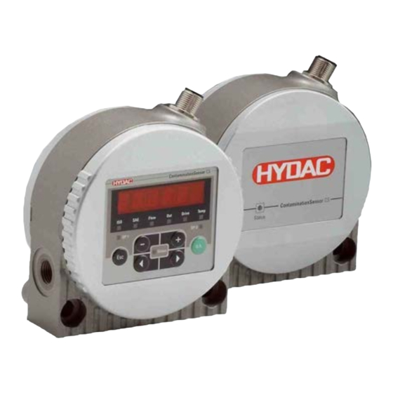
CS1000 Characteristics CS1000 Characteristics The ContaminationSensor Series CS1000 is a stationary measurement unit for the continuous monitoring of particulate contamination in hydraulic and lubrication systems. The CS is designed to be used in low- or high-pressure hydraulic and lubrication circuits and test benches where a small amount of oil (between 30 ml/min and 500 ml/min) is diverted for measurement purposes. -
Page 19: Cs1X1X Dimensions (Without Display)
CS1000 Characteristics CS1x1x dimensions (without display) All dimensions in mm. CS1x2x dimensions (with display) All dimensions in mm. ContaminationSensor CS1000 Page 19 / 136 en(us) BeWa CS1000 3764916d 300 en-us 2017-09-25.docx 2017-09-25... -
Page 20: Fastening/Mounting The Sensor
Fastening/Mounting the sensor Fastening/Mounting the sensor Install the CS in such a way that the flow runs from bottom to top. Use the one (lower) port as the INLET and the other (upper) port as the OUTLET. When selecting the installation site, take ambient factors like the temperature, dust, water, etc. -
Page 21: Continuous Rotation Of Sensor Display
Continuous rotation of sensor display 3. Installing on a mounting plate: Mount to a mounting plate or control block using 4 cylindrical screws having an M6 hexagonal socket according to ISO 4762. Continuous rotation of sensor display The display can be continuously rotated by a total of 270°;... -
Page 22: Hydraulic Sensor Connection
Hydraulic sensor connection Hydraulic sensor connection Determine the operating pressure of the hydraulic system and see whether it is within the permissible flow range for the CS inlet. NOTICE Excessive operating pressure The ContaminationSensor will be destroyed. ► Note the maximum operating pressure of 350 bar / 5075 psi. If possible, install the CS so that fluid flows from bottom to top to avoid air collecting in the sensor. -
Page 23: Selecting Connection Type According To Sensor Type
Hydraulic sensor connection Selecting connection type according to sensor type The sensor has the following described connection types. Pipe or hose connection (type CS1xxx-x-x-x-x-0/-xxx) The hydraulic connection is done via ports A and B. Connection thread G1/4 according to ISO 228. Make sure that the flow runs through the sensor from bottom (A) to top (B). -
Page 24: Flange Connection Type (Type Cs1Xxx-X-X-X-X-1/-Xxx)
Hydraulic sensor connection Flange connection type (Type CS1xxx-x-x-x-x-1/-xxx) The hydraulic connection is done via ports C and D. Two O-rings are used to form a seal between the CS and a flange, connecting plate or manifold mount. Four CS1000 threads are prepared for fixing the M6. Ports A and B are sealed off with screw plugs [1]. -
Page 25: Selecting Measurement Location At The Hydraulic Systems
Hydraulic sensor connection Selecting measurement location at the hydraulic systems In order to obtain cleanliness values that are continuous and coherent in real time, select a suitable measuring point according to the following guidelines: WRONG WRONG Select the measurement point so that the sample measured comes from a turbulent location, with a good flow. -
Page 26: Flow Rate, Differential Pressure And Viscosity Characteristics
Hydraulic sensor connection ∆ ν Flow rate, differential pressure and viscosity characteristics ∆ ν Differential pressure and viscosity characteristics. All the values indicated in the figures below apply regardless whether the direction of flow is A->B or B->A. Note that the permissible measured volumetric flow is 30 … 500 ml/min. If you are unable to achieve the required flow values, we offer an extensive line of accessories with various conditioning modules. -
Page 27: Connecting Hydraulic Sensor
Hydraulic sensor connection Connecting hydraulic sensor NOTICE Excessive operating pressure The ContaminationSensor will be destroyed. ► Note the maximum operating pressure of 350 bar / 5075 psi. Observe the following sequence when connecting the sensor to the hydraulic system: Connect the return line to the OUTLET of the CS. G1/4 ISO 228 threaded connection, recommended diameter of line ≥... -
Page 28: Electrical Connection Of Sensor
Supply voltage 9-36 V DC Analog output + (active) GND power supply GND ANALOG / SWITCH OUTPUTS HSI (HYDAC Sensor Interface) RS485 + RS485 - Switching output (passive, n.c.) The analogue output is an active source of 4 - 20 mA or 2 - 10 V DC. -
Page 29: Connection Cable - Assignment / Color Coding
Our accessories list on page 117 includes the required connection cables of various lengths with one connection plug (M12x1, 8-pole, according to DIN VDE 0627) and an open end. HYDAC accessory cable color coding is listed in the table below: Color Connection to... -
Page 30: Connecting Cable Ends - Examples
Electrical connection of sensor Connecting cable ends - Examples Schirm white Shield Blindage 24 V DC green Converter pink RS-485 + RS-485 blue RS-485 - grey brown SPS Eingang PLC Input yellow SPS Entrée 5 V DC Shield Circuit diagram: with two separate power supplies (e.g. 24 V DC and 5 V DC). -
Page 31: Setting The Measuring Mode
Setting the measuring mode Setting the measuring mode Once the sensor is switched on or supplied with power, it automatically runs in the measuring mode that has been set. Mode M1: Continuous measurement Application: Stand-alone sensor Data output: Display & RS485 & analog output Purpose: Measurement only Function:... -
Page 32: Mode M4: Filter To Continuously Monitor Cleanliness Class
Setting the measuring mode Mode M4: Filter to continuously monitor cleanliness class Application: Control of stationary offline filtration unit Data output: Display & RS485 & analog output & switching output Purpose: Establish continuous monitoring of cleanliness class between min./max. limit values. Function: Control of a filter unit, continuous measurement of solid particle contamination. -
Page 33: Mode "Single": Single Measurement
Setting the measuring mode Mode "SINGLE": Single measurement Application: Stand-alone sensor Data output: Display & RS485 & analog output Purpose: Perform a single measurement and "stop" the result. Function: Single measurement of solid particle contamination without switching functions. When Single Mode is selected in the menu, the display jumps directly to the following message after switching to the Measuring menu or after switching the CS on:... -
Page 34: Operating The Cs1X2X Sensor Using The Keypad
Operating the CS1x2x sensor using the keypad If the sensor is switched on or supplied with power, the display shows HYDAC CS1220 or 1320 depending on the type, in moving letters, then the firmware version is displayed for 2 seconds. -
Page 35: Function Of The Keys
Operating the CS1x2x sensor using the keypad Function of the Keys The following keys are available to you for operating and setting the CS1x2x: Function You jump one menu level down. o.k. You confirm a changed value at the lowest menu level. You confirm at the top menu level to save or reject a change in value. -
Page 36: Measured Variables On The Display
Operating the CS1x2x sensor using the keypad Measured variables on the display The measured variables give you information on the oil cleanliness in the system. You will receive a measured value with an accuracy of ± 1/2 ISO cleanliness class within the calibrated range. ISO (Cleanliness class) Display Description... -
Page 37: Service Variables On The Display
Operating the CS1x2x sensor using the keypad Service variables on the display The service variables inform you about the current status in the ContaminationSensor. The service variables are not calibrated and solely represent an approximate value for installing the sensor in the hydraulic system. Flow (flow rate) Display Description... -
Page 38: Activate / Deactivate Keypad Lock
Operating the CS1x2x sensor using the keypad Activate / deactivate keypad lock. Activate or deactivate the keypad lock by pressing both keys simultaneously to prevent further input. Keys The following appears in the Description display (1 sec) LOCK Activating key lock UNLOCK Deactivating key lock The display switches to the preset display after 1 second. -
Page 39: Activating Display
Operating the CS1x2x sensor using the keypad Activating display To activate or deactivate the history memory , press both keys simultaneously. function starts with the display of the most recent measured value. Keys The following appears in The following appears in <->... -
Page 40: Deactivating Display
Operating the CS1x2x sensor using the keypad Deactivating display If the display is set to in the PowerUp menu: Press the following two keys simultaneously to return to the current display: The display switches to the preset display. All values present in the memory are deleted. -
Page 41: Powerup Menu
Operating the CS1x2x sensor using the keypad PowerUp Menu You can carry out the basic settings for operation of the sensor in the PowerUp menu. Selection To do Press any key while the supply voltage to PowerUp Start menu the sensor is switched on / generated. Scroll through to and press PowerUp Exit the menu without... - Page 42 Operating the CS1x2x sensor using the keypad Select Description measurement mode Continuous measurement Continuous measurement and switching Filter to cleanliness class and stop Filter with continuous monitoring Single measurement Description Set measuring duration Set measuring duration (10 ... 300 seconds) ContaminationSensor CS1000 Page 42 / 136 en(us)
- Page 43 Operating the CS1x2x sensor using the keypad Set pump protection Description time 0 ... 10 number of measurement cycles. Please note that the pump can run dry with an M.TIME setting of 300 * 10 = 3000 seconds = 50 minutes. Description Set bus address (a,b, …...
- Page 44 Operating the CS1x2x sensor using the keypad Set FREEZE Display function FREEZE switched off Return to display manually via the key combination See page 32 for details. Return to automatic display after 10x the measurement duration Generate factory setting. Resetting to factory For factory settings see setting page 122.
-
Page 45: Measuring Menu (Cs12Xx)
Operating the CS1x2x sensor using the keypad Measuring Menu (CS12xx) During measurement operation, you can perform the following settings: Selection To do Start the measuring menu Press the key. Scroll through to and press the Exit the measuring menu key. without saving If a key is not pressed within 30 seconds, the system jumps back automatically. -
Page 46: Display After Sensor Is Switched On
Operating the CS1x2x sensor using the keypad - Display after sensor is switched on Description Set start display 3-digit ISO code SAE Class A SAE Class B SAE Class C SAE Class D SAE A-D Flow rate range Analog output in mA LED current in % Fluid temperature in °C Fluid temperature in °F... -
Page 47: Configure Switching Output
Operating the CS1x2x sensor using the keypad – Configure switching output Here you can adjust the behavior of the switching output. The measurement mode M1 / M2 / M3 / M4 / SINGLE is set in the PowerUp menu and can no longer be selected here. -
Page 48: M3 - Filter To Cleanliness Class And Stop
Operating the CS1x2x sensor using the keypad Switching function Limit values M3 – Filter to cleanliness class and stop Filter to cleanliness Description class and stop ISO Code SAE Class Target cleanliness M4 – Filter to continuously monitor cleanliness class Filter to Description continuously... -
Page 49: Single - Start Single Measurement + Stop
Operating the CS1x2x sensor using the keypad Target cleanliness Reactivation threshold Test cycle (1 to 1440 cycles, 1 cycle = 60 seconds) SINGLE - Start single measurement + stop Start single measurement + stop - Set output signal on analogue output The measured variable set here is output at the analog output (see page 66). - Page 50 Operating the CS1x2x sensor using the keypad SAE Class D Discard changes and exit Save changes and exit ContaminationSensor CS1000 Page 50 / 136 en(us) BeWa CS1000 3764916d 300 en-us 2017-09-25.docx 2017-09-25...
-
Page 51: Measuring Menu (Cs 13Xx)
Operating the CS1x2x sensor using the keypad Measuring Menu (CS 13xx) During measurement operation, you can perform the following settings: Selection To do Start Measuring menu Press the key. Scroll through to and press key. Scroll to CANCEL and actuate it If a key is not pressed within 30 seconds, the system jumps back automatically. -
Page 52: Display After Sensor Is Switched On
Operating the CS1x2x sensor using the keypad - Display after sensor is switched on Description Set start display 3-digit ISO code NAS class 2-5 µm NAS class 5-15 µm NAS class 15-25 µm NAS class > 25 µm NAS Maximum Flow rate range Analog output in mA LED current in %... -
Page 53: Configure Switching Output
Operating the CS1x2x sensor using the keypad – Configure switching output Here you can adjust the behavior of the switching output. The measurement mode M1 / M2 / M3 / M4 / SINGLE is set in the PowerUp menu and can no longer be selected here. -
Page 54: M3 - Filter To Cleanliness Class And Stop
Operating the CS1x2x sensor using the keypad Switching function Limit values M3 - Filter to cleanliness class and stop Description Filter to cleanliness class and stop ISO Code NAS Class Target cleanliness ContaminationSensor CS1000 Page 54 / 136 en(us) BeWa CS1000 3764916d 300 en-us 2017-09-25.docx 2017-09-25... -
Page 55: M4 - Filter To Continuously Monitor Cleanliness Class
Operating the CS1x2x sensor using the keypad M4 - Filter to continuously monitor cleanliness class Filter to Description continuously monitor cleanliness class ISO Code NAS Class Target cleanliness Reactivation threshold Test cycle (1 to 1440 cycles, 1 cycle = 60 seconds) SINGLE - Start single measurement + stop Start single... -
Page 56: Set Output Signal On Analogue Output
Operating the CS1x2x sensor using the keypad - Set output signal on analogue output The set measured variable is output via the analog output (see page 66). Set analog output - Description output signal NAS Maximum NAS class 2/5/15/25 (Code) NAS class+Temp. -
Page 57: Overview Of Menu Structure
Overview of menu structure Overview of menu structure Menu CS 12xx (ISO 4406:1999 and SAE) PowerUp Menu MODE Measurement mode Mode M1 Mode M2 Mode M3 Mode M4 SINGLE Mode Single mTIME Measuring time Change value pPRTC Pump protection time ADRESS Bus address HECOM... - Page 58 Overview of menu structure ANaOUT Analog output SAeMAX SAE A-D SAE Class A/B/C/D SAE+T SAE class A/B/C/D + temperature TEMP Temperature HDaISO HDA+ISO HDaSAE HDA+SAE ISO 4 ISO Code 4µm ISO 6 ISO Code 6µm ISO 14 ISO Code 14µm ISO Code ISO+T ISO code + temperature...
-
Page 59: Menu Cs 13Xx (Iso 4406:1987 And Nas / Iso4406:1999 Und Sae 4059)
Overview of menu structure Menu CS 13xx (ISO 4406:1987 and NAS / ISO4406:1999 und SAE 4059) PowerUp Menu Measuring mode Mode M1 Mode M2 Mode M3 Mode M4 Mode Single Measuring time Pump protection Bus address HECOM3b address Reserved Reserved Display Freeze Manual Automatic... - Page 60 Overview of menu structure Analog output NAS Maximum NAS + temperature Temperature HDA+ISO HDA+SAE ISO Code 4µm ISO Code 6µm ISO Code 14µm ISO Code ISO code + temperature NAS 2-5 µm NAS 5-15 µm NAS 15-25 µm NAS >25 µm Discard changes and exit Discard changes and exit ContaminationSensor CS1000...
-
Page 61: Menu Cs 13Xx (Iso 4406:1987 And Nas / Iso4406:1999 Und Sae 4059)
Overview of menu structure Menu CS 13xx (ISO 4406:1987 and NAS / ISO4406:1999 und SAE 4059) PowerUp Menu Measuring menu ContaminationSensor CS1000 Page 61 / 136 en(us) BeWa CS1000 3764916d 300 en-us 2017-09-25.docx 2017-09-25... - Page 62 Overview of menu structure ContaminationSensor CS1000 Page 62 / 136 en(us) BeWa CS1000 3764916d 300 en-us 2017-09-25.docx 2017-09-25...
-
Page 63: Using Switching Output
Using switching output Using switching output You can use the switching output in the modes described below. For a further description of the measurement modes, see page 31. Mode M1: Continuous measurement Purpose: Measurement only Function: Continuous measurement of cleanliness class Switching function only for "Device ready". -
Page 64: Setting Limit Values
Setting limit values Setting limit values After completing the boot sequence, the switching output (SP1) will become conductive. This condition is maintained for the initial measurement duration (WAIT period). Depending on the measurement mode, the switching output can be used as a Device ready function. Switching output –... - Page 65 Setting limit values Mode M3 Switching output – OPEN Switching output – LED of SP1 – off CONDUCTIVE LED of SP1 – on 5 consecutive measured values ≤ Measurement is currently in progress and one or more of the limit value ( ) or last 5 measured values >...
-
Page 66: Reading The Analog Output
Reading the analog output Reading the analog output Using the analog output, the measured values can be issued in time-coded form. The transfer, depending on the settings, takes up to 52 seconds to complete and once the measuring time is up, that is, when there is a new measured value, will not be cancelled. -
Page 67: Sae - Classes Acc. To As 4059
Reading the analog output SAE - classes acc. to AS 4059 The following SAE values can be read out via the analogue output: • SAE A-D (SAEMAX) Only one single value is output. • / / C / SAE A D All values are sequentially time-coded before output. - Page 68 Reading the analog output The current (I) or voltage (U) can be calculated for a given SAE contamination class as follows: I = 4.8 mA + SAE class x (19.2 mA - 4.8 mA) / 14 U = 2.4 V + SAE class x (9.6 V - 2.4 V) / 14 The current (I) or voltage (U) can be calculated for a given SAE contamination class as follows: SAE class = (I - 4.8 mA) x (14/14.4 mA)
-
Page 69: Sae A-D
Reading the analog output SAE A-D value is the highest class in any of one of the four SAE A-D classes (respectively >4 µm , >6 µm , >14 µm , >21 µm The signal is updated after the measuring period has elapsed (the measuring period is set in the PowerUp menu, factory setting = 60 s). -
Page 70: Sae Classes A / B / C / D
Reading the analog output SAE classes A / B / C / D The SAE class A/B/C/D signal consists of 4 measured values transmitted with the following time-coded time slices: I (mA) U (V) 20,0 10,0 19,8 19,7 9,85 9,75 19,5 19,2 High... -
Page 71: Sae A / Sae B / Sae C / Sae D
Reading the analog output SAE A / SAE B / SAE C / SAE D The SAE X signal consists of a measured value (SAE A / SAE B / SAE C / or SAE D) which is permanently transmitted as described in the following. = Duration of the measurement as set in the PowerUp menu, see page 41. -
Page 72: Sae + T
Reading the analog output SAE + T The SAE+T signal consists of 5 measured values which are transmitted time- coded with the following time slices: U (V) I (mA) 10,0 19,8 19,7 9,85 19,5 9,75 19,2 High High 3000 3000 3000 3000 2,25... -
Page 73: Hda.sae - Analog Signal Sae For Hda 5500
Reading the analog output HDA.SAE – Analog signal SAE for HDA 5500 The HDA.SAE signal consists of 6 values (START / SAE A / SAE B / SAE C / SAE D / Status) which are output sequentially. Synchronization with the downstream control unit is a prerequisite. -
Page 74: Hda.sae Signal 1/2/3/4
Reading the analog output HDA.SAE Signal 1/2/3/4 The current or voltage range is dependent on the contamination class according to SAE=0.0 – 14.0 (resolution 0.1 class). Current I SAE class / error Voltage U I < 4.00 mA Cable break U<... -
Page 75: Hda.sae Signal 5 (Status)
Reading the analog output HDA.SAE Signal 5 (Status) The current or voltage of the output signal 5 is, depending on the status of the CS1000, described as shown in the table below. Current I Status Voltage U I = 5.0 mA The CS is functioning correctly U = 2.5 V I = 6.0 mA... - Page 76 Reading the analog output If the status signal is 8.0 mA or 4.0 V, signals 1 to 4 are output as follows: Signal Current I Voltage U SAE Class 4.0 mA 2.0 V 4.0 mA 2.0 V 4.0 mA 2.0 V 4.0 mA 2.0 V ContaminationSensor CS1000...
-
Page 77: Iso Code According To Iso 4406:1999
Reading the analog output ISO code according to ISO 4406:1999 The following ISO values can be read out via the analogue output: • ISO 4 / ISO 6 / ISO 14 Only one value is output. • ISO code in 3 figures ( >4µm / >6µm / >14µm All values are sequentially time-coded before output. -
Page 78: Iso 4 / Iso 6 / Iso 14
Reading the analog output ISO 4 / ISO 6 / ISO 14 The ISO X signal consists of a measured value (> 4 µm or > 6 µm or > 14 µm) which is permanently transmitted, as described in the following. = Duration of the measurement as set in the PowerUp menu, see page 41. -
Page 79: Iso Code, 3-Digit
Reading the analog output ISO Code, 3-digit The ISO code signal consists of 3 measured values (>4µm / >6µm >14µm ) which are transmitted time-coded. U (V) I (mA) 19,8 19,7 9,85 19,5 9,75 19,2 High High 3000 3000 3000 2,15 2,05 t (ms) -
Page 80: Iso + T
Reading the analog output ISO + T The ISO+T signal consists of 4 measured values which are transmitted time- coded with the following time slices: U (V) I (mA) 19,8 9,85 19,7 9,75 19,5 19,2 High High 3000 3000 3000 2,15 2,05 time (ms) -
Page 81: Hda.iso - Analog Signal Iso For Hda 5500
Reading the analog output HDA.ISO – Analog signal ISO for HDA 5500 The HDA.ISO signal consists of 6 measured values (START / ISO 4 / ISO 6 / ISO 14 / ISO 21 / Status) which are output sequentially. Synchronization with the downstream control unit is a prerequisite. -
Page 82: Hda.iso Signal 1/2/3/4
Reading the analog output HDA.ISO Signal 1/2/3/4 The current 4-20 mA or voltage 2-10 V of the output signal, dependent on the ISO contamination class being 0.0 - 24.28 (resolution 1 class), is described as below: Current I ISO Code Voltage U I <... -
Page 83: Hda.iso Signal 5 (Status)
Reading the analog output HDA.ISO Signal 5 (Status) The current or voltage of the output signal 5 is, depending on the status of the CS1000, described as shown in the table below. Current I Status Voltage U I = 5.0 mA The CS is functioning correctly U = 2.5 V I = 6.0 mA... - Page 84 Reading the analog output If the status signal is 8.0 mA or 4.0 V, signals 1 to 4 are output as follows: Signal Current I Voltage U ISO value 9.93 mA 4.97 V 9.27 mA 4.64 V 8.61 mA 4.31 V 7.95 mA 3.98 V U V ( )
-
Page 85: Isoiso Code Signal Acc. To Iso 4406:1987 (Cs 13Xx Only)
Reading the analog output ISOISO code signal acc. to ISO 4406:1987 (CS 13xx only) The following ISO values can be read out via the analogue output: • ISO 2 / ISO 5 / ISO 15 Only one value is output. •... - Page 86 Reading the analog output The ISO X signal consists of a measured value (> 2 µm or > 5 µm or > 15 µm) which is permanently transmitted, as described in the following. = Duration of the measurement as set in the PowerUp menu, see page 41.
-
Page 87: Iso Code, 3-Digit
Reading the analog output ISO Code, 3-digit The ISO code signal consists of 3 measured values (>2 µm / >5 µm / >15 µm) which are transmitted time-coded as shown below. U (V) I (mA) 19,8 19,7 9,85 19,5 9,75 19,2 High High... -
Page 88: Iso + T
Reading the analog output ISO + T The ISO+T signal consists of 4 measured values which are transmitted time- coded with the following time slices: U (V) I (mA) 19,8 9,85 19,7 9,75 19,5 19,2 High High 3000 3000 3000 2,15 2,05 time (ms) -
Page 89: Hda.iso - Analog Signal Iso For Hda 5500
Reading the analog output HDA.ISO – Analog signal ISO for HDA 5500 The HDA.ISO signal consists of 4 measured values (ISO 4 / ISO 6 / ISO 14 / ISO 21 / Status) which are output sequentially. Synchronization with the downstream control unit is a prerequisite. -
Page 90: Hda.iso Signal 1/2/3/4
Reading the analog output HDA.ISO Signal 1/2/3/4 The current 4-20 mA or voltage 2-10 V of the output signal, depending on the ISO contamination class 0.0 - 24.28 (resolution 1 class), is described as below: Current I ISO Code Voltage U I <... -
Page 91: Hda.iso Signal 5 (Status)
Reading the analog output HDA.ISO Signal 5 (Status) The current or voltage of the output signal 5 is, depending on the status of the CS1000, described as shown in the table below. Current I Status Voltage U I = 5.0 mA The CS is functioning correctly U = 2.5 V I = 6.0 mA... - Page 92 Reading the analog output If the status signal is 8.0 mA or 4.0 V, signals 1 to 4 are output as follows: Signal Current I Voltage U ISO value 9.93 mA 4.97 V 9.27 mA 4.64 V 8.61 mA 4.31 V 7.95 mA 3.98 V U V ( )
-
Page 93: Nas 1638 - National Aerospace Standard (Cs 13Xx Only)
Reading the analog output NAS 1638 - National Aerospace Standard (CS 13xx only) The following NAS values can be read out via the analogue output: • NAS Maximum Only one value is output. • NAS (2 / 5 / 15 / 25) All values are sequentially time-coded before output. -
Page 94: Nas Maximum
Reading the analog output The current (I) or voltage (U) can be calculated for a given NAS contamination class as follows: I = 4.8 mA + NAS class x (19.2 mA - 4.8 mA) / 14 U = 2.4 V + NAS class x (9.6 V - 2.4 V) / 14 The current (I) or voltage (U) can be calculated for a given NAS contamination class as follows: NAS class = (I - 4.8 mA) x (14/14.4 mA) -
Page 95: Nas Classes (2 / 5 / 15 / 25)
Reading the analog output NAS classes (2 / 5 / 15 / 25) The NAS classes 2 / 5 / 15 / 25 signal consists of 4 measured values transmitted with the following time-coded time slices: I (mA) U (V) 20,0 10,0 19,8... -
Page 96: Nas 2 / Nas 5 / Nas 15 / Nas 25
Reading the analog output NAS 2 / NAS 5 / NAS 15 / NAS 25 The NAS X signal consists of a measured value (NAS 2 / NAS 5 / NAS 15 / or NAS 25) which is permanently transmitted as described in the following. = Duration of the measurement as set in the PowerUp menu, see page 41. -
Page 97: Nas + T
Reading the analog output NAS + T The NAS+T signal consists of 5 measured values which are transmitted time- coded with the following time slices: U (V) I (mA) 10,0 19,8 19,7 9,85 19,5 9,75 19,2 High High 3000 3000 3000 3000 2,25... -
Page 98: Hda.nas - Analog Signal Nas For Hda 5500
Reading the analog output HDA.NAS – Analog signal NAS for HDA 5500 The HDA.NAS signal consists of 4 measured values (Start / NAS 2 / NAS 5 / NAS 15 / NAS 25 / Status) which are output sequentially. Synchronization with the downstream control unit is a prerequisite. -
Page 99: Hda.nas Signal 1/2/3/4
Reading the analog output HDA.NAS Signal 1/2/3/4 The current or voltage range is dependent on the contamination class according to NAS=0.0 - 14.0 (resolution 0.1 class). Current I NAS class / error Voltage U I < 4.00 mA Cable break U<... -
Page 100: Hda.nas Signal 5 (Status)
Reading the analog output HDA.NAS Signal 5 (Status) The current or voltage of the output signal 5 is, depending on the status of the CS1000, described as shown in the table below. Current I Status Voltage U I = 5.0 mA The CS is functioning correctly U = 2.5 V I = 6.0 mA... - Page 101 Reading the analog output If the status signal is 8.0 mA or 4.0 V, signals 1 to 4 are output as follows: Signal Current I Voltage U NAS Class 4.0 mA 2.0 V 4.0 mA 2.0 V 4.0 mA 2.0 V 4.0 mA 2.0 V ContaminationSensor CS1000...
-
Page 102: Fluid Temperature Temp
Reading the analog output Fluid temperature TEMP The current range 4.8-19.2 mA or voltage range 2.4-9.6 V is, depending on the fluid temperature of -25°C-100°C (resolution: 1°C) or -13°F-212°F (resolution: 1°F), as shown in the table below. Current I Temperature / Error Voltage U I <... -
Page 103: Status Messages
Status Messages Status Messages Status LED / Display Error Flash code / Status Remedy display Analog output Switching output Flow status on the digital output current value CS o.k. mA / V* Conductive Reduce the flow The flow rate has rate to prevent the reached the upper sensor from going... - Page 104 Status Messages Error Flash code / Status Remedy display Analog output Switching output Flow status on the digital output Do nothing. The The flow rate is in sensor is in the the middle current value middle flow rate permissible range. mA / V* range.
- Page 105 Status Messages Error Flash code / Status Remedy display Analog output Switching output Flow status on the digital output <)<(</ The sensor is below the measurement range limit ISO 9/8/7. current value mA / V* Conductive The sensor is below the measurement range limit SAE 0.
-
Page 106: Error
Status Messages Error Error Flash code / Status To do display Analog output Switching output Flow status on the digital output Check that the flow is between 30 … CHECK 500 ml/min. If the fluid It is not possible to cleanliness is below determine the flow the measurement... -
Page 107: Exceptions Errors
Check the supply voltage for the CSr. no display 0 mA / 0 V* no function. Contact HYDAC. open Reset the unit. (To do this, disconnect the CS from the voltage supply) or 4.1 mA / 2.05 V* contact HYDAC. - Page 108 Flow status on the digital output Reset the unit. (To do this, disconnect the CS from the voltage supply) or 4.1 mA / 2.05 V* contact HYDAC. System error -40…-69 open Reset the unit. (To do this, disconnect the CS from the voltage supply) 4.1 mA / 2.05 V*...
-
Page 109: Analog Output Error Signals
Status Messages Analog Output Error Signals If the CS enters into an error status all following measured value signals are output in a specific current strength (I) or voltage (U). Please refer to chapter "Error status" for the respective values for the current strength or voltage of the output signal during an error status). -
Page 110: Analog Signal For Hda 5500
Status Messages Analog signal for HDA 5500 HDA Status Signal 5 Table The current or voltage of the analog signal (5) is, depending on the status of the CS1000, as shown in the table below. Current I Status Voltage U I = 5.0 mA The CS is functioning correctly U = 2.5 V... - Page 111 Status Messages If the status signal is 8.0 mA or 4.0 V, signals 1 to 4 are output as follows: Signal U V ( ) I mA t s ( ) 2 2 2 2 2 2 2 2 2 2 2 2 2 2 2 2 2 2 2 2 2 2 ContaminationSensor CS1000 Page 111 / 136...
-
Page 112: Connecting Csi-D-5 (Condition Sensor Interface)
Connecting CSI-D-5 (Condition Sensor Interface) Connecting CSI-D-5 (Condition Sensor Interface) With the CSI-D-5 and connected PC, you can set parameters and limit values as well as export online measured data from the sensor. CSI-D-5 connection overview Connect the CSI-D-5 to the CS according to the following connection diagram. -
Page 113: Connecting The Sensor To A Rs485 Bus
Connecting the sensor to a RS485 Bus Connecting the sensor to a RS485 Bus The RS485 interface on the CS1000 is a two-wire interface and operates in half-duplex mode. The number of CS1000s per RS485 bus is limited to 26. Use letters A to Z to address the HECOM bus address. -
Page 114: Reading Out / Setting The Sensor Via The Rs485 Bus
Reading out / setting the sensor via the RS485 bus Reading out / setting the sensor via the RS485 bus Use the following settings to communicate via the COM interface: Bits per second = 9600 Baud Data bits Parity = None Stop bits report = None... -
Page 115: Evaluating/Reading Measurement Reports With Flumos
FluMoS light is available as freeware on the CD included in the delivery or as a download. You will find the link for the download on our homepage at www.hydac.com. You can order FluMoS professional as a fee- based accessory. -
Page 116: Performing Maintenance
We recommend recalibrating the sensor every 2-3 years unless otherwise specified at a HYDAC-certified Customer Service or Service Center. Addresses can be found on page 120 or on www.hydac.com. Cleaning the display / user interface Clean the display / control panel with a clean, moist cloth. Do not use any chemical cleaning agents as these may damage the film attached to the surface of the unit. -
Page 117: Spare Parts And Accessories
HDA5500-0-2-DC- 909926 You will find other electrical and hydraulic accessories for fluid sensors in our general accessories brochure no. 7623. This brochure can be downloaded free of charge from our website www.hydac.com. ContaminationSensor CS1000 Page 117 / 136 en(us) BeWa CS1000 3764916d 300 en-us 2017-09-25.docx... -
Page 118: Technical Data
Technical Data Technical Data General data Mounting position Any (recommended: vertical position) Self diagnostics continuously with error indication via status LED and display Display (only CS 1x2x) LED, 6 digits, in 17 segment format Measured variables CS 12xx ISO / SAE CS 13xx ISO / SAE / NAS Measurement range... - Page 119 2 A, maximum switching voltage 30 V DC, dead open RS485 interface 2 wire, half duplex HSI (HYDAC Sensor Interface) 1 wire, half duplex ContaminationSensor CS1000 Page 119 / 136 en(us) BeWa CS1000 3764916d 300 en-us 2017-09-25.docx...
-
Page 120: Annex
Friedrichsthaler Straße 15A 66540 Neunkirchen-Heinitz Telephone: +49 6897 509 883 Fax: +49 6897 509 324 E-mail: service@hydac.com HYDAC Technology Corporation, HYCON Division 2260 City Line Road USA-Bethlehem, PA 18017 P.O. Box 22050 USA-Lehigh Valley, PA 18002-2050 Telephone: +1 610 266 0100 Fax:... -
Page 121: Brazil
+55 11 4393.6600 Fax: +55 11 4393.6617 E-mail: hydac@hydac.com.br Homepage www.hydac.com.br China HYDAC TECHNOLOGY (SHANGHAI) LIMITED 28 Zhongpin Lu Shanghai Minhang Economic & Technological Development Zone SHANGHAI 200245; P.R. CHINA Telephone: +86 21 64 63 35 10 Fax: +86 21 64 30 02 57 E-mail: hydacsh@hydac.com.cn... -
Page 122: Checking/Resetting Default Settings
Annex Checking/resetting default settings PowerUp Menu PowerUp Menu value Mode value Measuring menu Measuring menu value ContaminationSensor CS1000 Page 122 / 136 en(us) BeWa CS1000 3764916d 300 en-us 2017-09-25.docx 2017-09-25... -
Page 123: Model Code
Annex Model code 0 - A - 0 - 0 - 0 - 0 /- 000 Product CS = ContaminationSensor Series = 1000 Series Contamination code = ISO4406:1999; SAE AS4059 = ISO4406:1987; NAS 1638 ISO4406:1999; SAE AS4059 Options = without display = with display, continuously variable rotation by 270°... -
Page 124: Cleanliness Classes - Brief Overview
Annex Cleanliness classes - brief overview Cleanliness class - ISO 4406:1999 In ISO 4406:1999, particle counts are determined cumulatively, i.e. > 4 µm >6 µm and >14 µm (manually by filtering the fluid through an analysis membrane or automatically using particle counters) and allocated to measurement references. -
Page 125: Overview Of Modifications - Iso4406:1987 <-> Iso4406:1999
Annex Note: increasing the measurement reference by 1 causes the particle count to double. Example: ISO Code 18 / 15 / 11 says: Cleanliness class Particle count / ml Size ranges 1,300 – 2,500 > 4 µm 160 – 320 >... -
Page 126: Cleanliness Class - Sae As 4059
Annex Cleanliness class - SAE AS 4059 Like ISO 4406, SAE AS 4059 describes particle concentrations in fluids. The analysis methods can be applied in the same manner as ISO 4406:1999. An additional feature in common with ISO 4406:1999 is that cleanliness classes are grouped on the basis of cumulative number of particles (i.e. -
Page 127: Definition Acc. To Sae
Annex Definition acc. to SAE Particle count (absolute) larger than a defined particle size Example: Cleanliness class acc. to AS 4059=6 The maximum permissible particle count in the individual size ranges is bold- faced in the table on page 126. Cleanliness class to AS 4059= 6B Size B particles may not exceed the maximum number indicated for code 6: 6 B = max. -
Page 128: Cleanliness Class - Nas 1638
Annex Cleanliness class - NAS 1638 Like ISO 4406, NAS 1638 describes particle concentrations in fluids. The analysis methods can be applied in the same manner as ISO 4406:1987. In contrast to ISO 4406, certain particle ranges are counted in NAS 1638 and attributed to key figures. -
Page 129: Egdeclaration Of Conformity
Annex - EGDeclaration of conformity Request an EG declaration of conformity from HYDAC, if necessary. The contact data can be found on Page 8. Glossary Single A single measurement means the analysis of the measurement contamination in a sample, which flows through the sensor during the configured measurement period. -
Page 130: Explanation Of Terms And Abbreviations
European Union FLOW See page 37 for details. FluMoS See page 115 for details. FluMoT See page 115 for details HYDAC Measuring device HYDAC Sensor interface Inlet INLET Inlet Classification of the solid particle contamination, details see page 124 Light-emitting diode... -
Page 131: Displays
ADRESS Bus address setup ANAOUT Analog output, see page 66 for details. CALIB Calibration selection CANCEL Cancel CODE With password-protected area for HYDAC DFAULT Factory setting DRIVE Transmission power of the LED in digits DSPLAY Display FREEZE Key protection activation... -
Page 132: Index
Annex Index DRIVE 57, 130, 131 DSPLAY 57, 131 Accessories 24, 117 accident prevention 12 Accuracy 118 Electrical data 119 ambient temperature 118 Error 102, 103, 106, 107, 108, 109 Analog signal 73, 81, 89, 98, 110 export 112 Analogue output 37 ANAOUT 131 Application 31, 32, 33 Assignment 28, 29, 124... - Page 133 Annex IP 57, 118, 131 ISO 18, 20, 21, 23, 27, 34, 35, 36, 46, 48, 49, 52, 54, 55, 56, 57, 58, 59, 60, 61, 66, 77, 78, 79, 80, Parity 114 81, 82, 83, 84, 85, 86, 87, 88, 89, 90, 91, 92, Power consumption 119 105, 106, 110, 118, 119, 124, 125, 126, 128, Proper/Designated Use 12...
- Page 134 Annex Wall mounting 20 Weight 118 WITHIN 57 ContaminationSensor CS1000 Page 134 / 136 en(us) BeWa CS1000 3764916d 300 en-us 2017-09-25.docx 2017-09-25...
- Page 136 HYDAC FILTER SYSTEMS GMBH Industriegebiet Postfach 1251 66280 Sulzbach/Saar 66273 Sulzbach/Saar Germany Germany Tel: +49 6897 509 01 Central Fax: +49 6897 509 9046 Technology Fax: +49 6897 509 577 Sales Department Internet: www.hydac.com E-Mail: filtersystems@hydac.com...
Need help?
Do you have a question about the CS1000 series and is the answer not in the manual?
Questions and answers