
Subscribe to Our Youtube Channel
Related Manuals for Hydac SMU 1200


Summary of Contents for Hydac SMU 1200
- Page 1 SMU 1200 SensorMonitoring Unit Operating Instruction Valid from firmware versions V2.0 up English (translation of original instructions) Document No.: 3854281...
-
Page 2: Imprint
Court of Registration: Saarbrücken, HRB 17216 Executive Director: Mathias Dieter, Dipl.Kfm. Wolfgang Haering Documentation Representative Mr. Günter Harge c/o HYDAC International GmbH, Industriegebiet, 66280 Sulzbach / Saar Telephone: ++49 (0)6897 509 1511 Telefax: ++49 (0)6897 509 1394 E-Mail: guenter.harge@hydac.com © HYDAC FILTER SYSTEMS GMBH All rights reserved. -
Page 3: Table Of Contents
Content Content Imprint......................2 Documentation Representative ..............2 Content ......................3 Preface......................7 Technical Support..................8 Modifications to the Product ................8 Warranty ......................8 Using the documentation ................9 Safety information ..................10 Hazard symbols..................10 Signal words and their meaning in the safety information and instructions ....................11 Structure of the safety information and instructions........11 Observe regulatory information ..............12 Proper/Designated Use ................12 Improper Use or Use Deviating from Intended Use ........14... - Page 4 Content Interface G....................31 HSI (Hydac Sensor Interface) – SMU 126x … ........31 ETH (Ethernet) – SMU 127x … ..............31 Connecting the sensors ................32 Examples of connection................34 SMU126x <-> CS1000 / AS1000...............34 SMU12x1 <-> Bluetooth ................35 SMU127x <-> CS1000 / AS1000 -> LAN...........36 Operating the SMU..................37...
- Page 5 Content DAT.TIM – date / time ................52 ADRESS – Setting HSI bus address / TCP/IP address......53 REC.MOD – Set data recording .............55 DEL.MEM – Delete Memory..............56 SENS A – Sensor A PowerUp menu............57 SENS B – Sensor B PowerUp menu............59 SEN.ADR –...
- Page 6 Content Accessories....................93 Technical data .....................95 Overview - Compatible USB sticks............96 EC declaration of conformity ..............97 Index ......................98 SensorMonitoring Unit - SMU en(us) Page 6 / 100 BeWa SMU1200 3854281 V2.0x en(us) 2013-08-20 2013-08-20...
-
Page 7: Preface
If you discover errors while reading the documentation or have suggestions or other useful information, please don’t hesitate to contact us: HYDAC FILTER SYSTEMS GMBH Technische Dokumentation Postfach 12 51... -
Page 8: Technical Support
After modification or repair work that affects the safety of the product has been carried out on components, the product may not be returned to operation until it has been checked and approved by a HYDAC technician. Please notify us immediately of any modifications made to the product whether by you or a third party. -
Page 9: Using The Documentation
Preface Using the documentation Note that the method described for locating specific information does not release you from your responsibility of carefully reading all these instructions prior to starting the unit up for the first time and at regular intervals in the future. WHAT do you want to know? I determine which topic I am looking for. -
Page 10: Safety Information
Safety information Safety information The device was built according to the statutory provisions valid at the time of delivery and satisfies current safety requirements. Any residual hazards are indicated by safety information and instructions and are described in the operating instructions. Observe all safety and warning instructions attached to the unit. -
Page 11: Signal Words And Their Meaning In The Safety Information And Instructions
Safety information Signal words and their meaning in the safety information and instructions DANGER DANGER indicates a hazard with a high risk and which will lead to death or serious injury if not avoided. WARNING WARNING indicates a hazard with a medium risk and which can lead to death or serious injury if not avoided. -
Page 12: Observe Regulatory Information
Safety information Observe regulatory information Also observe the following regulatory information and guidelines: Legal and local regulations for accident prevention Legal and local regulations for environmental protection Country-specific regulations, organization-specific regulations Proper/Designated Use WARNING Strong magnets on the SMU Life-threatening danger for persons with cardiac pacemakers Maintain sufficient clearance between... - Page 13 Any other use shall be deemed to be improper and not in keeping with the product's designated use. HYDAC accepts no liability for any damage resulting from such use. Proper or designated use of the product extends to the following: ...
-
Page 14: Improper Use Or Use Deviating From Intended Use
Any use extending beyond or deviating therefrom shall not be considered intended use. HYDAC Filter Systems GmbH will assume no liability for any damage resulting from such use. The user alone, shall assume any and all associated risk Improper use may result in hazards and/or will damage the sensor. -
Page 15: Qualifications Of Personnel / Target Group
Safety information Qualifications of personnel / target group Persons who work on the sensor must be aware of the associated hazards when using it. Auxiliary and specialist personnel must have read and understood the operating instructions, in particular the safety information and instructions, and applicable regulations before beginning work. -
Page 16: Storing The Smu
Storing the SMU Storing the SMU Make sure to store the SMU in a clean, dry place, in the original packing, if possible. Do not remove the packing until you are ready to install the unit. Storage conditions Storage temperature: -40 °C …... -
Page 17: Transporting The Smu
Transporting the SMU Transporting the SMU WARNING Strong magnetic field around the magnets Life-threatening danger for persons with cardiac pacemakers Maintain sufficient clearance between ► yourself and the magnets NOTICE Strong magnetic field around the magnets Magnetic strips and magnetizable objects can be damaged. Maintain sufficient clearance from magnetic strips on credit cards, ►... -
Page 18: Decoding The Type Label
Decoding the type label Decoding the type label For identification details of the SMU, see the type label. This is located on the back of the unit and contains the exact product description and the serial number. -> Description Model ->... -
Page 19: Checking The Scope Of Delivery
Checking the scope of delivery Checking the scope of delivery The SMU comes packed and factory-assembled. Before commissioning the SMU, check the content of the package to make sure everything is present. The following items are supplied: Item Qty. Designation SensorMonitoring Unit SMU USB Memory stick Connection cable, 5-pin with... -
Page 20: Smu Features
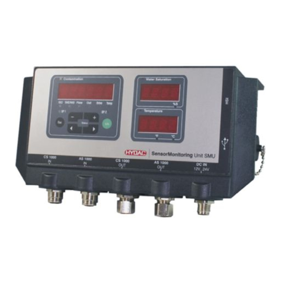
SMU Features SMU Features The SensorMonitoring Unit SMU is used for the presentation and memory storage of the measured values of Fluid Sensors. The following fluid sensors can be connected directly, depending on the SMU model: ContaminationSensor CS1000 (sensor interface A) Metal ContaminationSensor MCS1000 (sensor interface A) AquaSensor AS1000 (Sensor interface B) The measured values for the connected sensors are shown on the display. -
Page 21: Dimensions
Dimensions Dimensions Rear view: SensorMonitoring Unit - SMU en(us) Page 21 / 100 BeWa SMU1200 3854281 V2.0x en(us) 2013-08-20 2013-08-20... -
Page 22: Fastening / Mounting The Smu
Fastening / Mounting the SMU Fastening / Mounting the SMU The SMU has the following two types of mounting as standard features WARNING Strong magnetic field around the magnets Life-threatening danger for persons with cardiac pacemakers Maintain sufficient clearance between ►... -
Page 23: Fastening The Smu Temporarily To Magnetizable Surfaces
Fastening / Mounting the SMU Fastening the SMU temporarily to magnetizable surfaces The four high-performance magnets on the rear side provide fastening to metallic surfaces. Use the top hat rail mounting technique for permanent fastening, see page 24 The SMU can be readily released from the metallic surface by tilting. SensorMonitoring Unit - SMU en(us) Page 23 / 100... -
Page 24: Permanent Fastening Of The Smu On The Top Hat Rail
Fastening / Mounting the SMU Permanent fastening of the SMU on the top hat rail The SMU has a top hat rail receptacle on its rear side for the purpose of fastening it to 35 mm top hat rails in accordance with DIN EN 60715 TH35. To accomplish this, mount the top hat rail included in the scope of delivery to the desired position with 2 screws or use the top hat rail to be found in the control cabinet. -
Page 25: Connecting The Smu
Connecting the SMU Connecting the SMU Note the many different interfaces on the SMU before connecting. Described in detail in the following overview. SMU interface overview The SMU has sensor interfaces and interfaces as indicated below. Connection Description Sensor Interface A Sensor Interface B Interface, additional signals from sensor interface A Interface, additional signals from sensor interface B... - Page 26 Connecting the SMU The sensor interfaces A/B are each prepared for one particular sensor. The sensor for the sensor interface A / B can be found in the front foil lettering and/or on the model code on page 91. Additional signals from the sensors to the sensor interface A/B are available at the interfaces C/D.
-
Page 27: Sensor Interface A - Cs1000 In / Mcs1000 In
Connecting the SMU Sensor interface A - CS1000 IN / MCS1000 IN Connect the sensor CS1000 / MCS1000 with this connection. Sensor Interface B - AS1000 IN Connect the sensor AS1000 with this connection. Interface C - CS1000 OUT / MCS1000 OUT Here the output signals of a connected CS1000 or MCS1000 can be tapped into for further utilization. -
Page 28: 8-Pin Connection Cable, Open Cable End
Connecting the SMU 8-pin connection cable, open cable end: Schirm weiss / white / blanc Shield Blindage braun / brown / brun grün / green / vert gelb / yellow / jaune grau / grey / gris rosa / pink / rose blau / blue / bleu rot / red / rouge Schirm / Shield / Blindage... -
Page 29: Interface D - As1000 Out
Connecting the SMU Interface D - AS1000 OUT Here you can tap into the output signals of a connected AS1000 for further utilization. The bus signals such as RS485 and HSI are not transferred by the sensor. The SMU has its own HSI interface (G). Our accessories list includes connection cables of different lengths with one connector and the following configuration: Color code... -
Page 30: Interface E - Voltage Supply
Connecting the SMU Interface E - voltage supply Connect the connection cable for supply voltage contained in the scope of delivery in accordance with the following table: Color code Designation brown Voltage 12 … 24 V DC White blue black grey The assignment of the interface is as follows: Designation... -
Page 31: Interface G
The G interface is designed as an HSI or Ethernet interface depending on the SMU version. Please refer to the following description. HSI (Hydac Sensor Interface) – SMU 126x … The following HYDAC devices can be connected to the HSI interface: - HMG3000 Manual Measuring Unit - CSI-F-10... -
Page 32: Connecting The Sensors
Connecting the sensors Connecting the sensors Before connection, check the model/type designation or sensor imprint of the SMU in connection with the sensors that you plan to use. The sensors are connected through the unit plugs on the underside of the SMU. The analog outputs and/or the switching outputs of the sensors are looped through and are available for further use at the 8-pin or 5-pin outlet socket. - Page 33 Connecting the sensors At the time of delivery, the following sensors have the factory setting: Sensor HSI bus address: CS1000 MCS1000 AS1000 No address Set the AS1000 to a fixed HSI bus address. Carry out the setting of the HSI bus address in the PowerUp menu.
-
Page 34: Examples Of Connection
Examples of connection Examples of connection You will find SMU connection examples in the subsequent chapters. SMU126x <-> CS1000 / AS1000 All of the cables required for connection are to be found in the scope of delivery of the SMU. SensorMonitoring Unit - SMU en(us) Page 34 / 100... -
Page 35: Smu12X1 <-> Bluetooth
Examples of connection SMU12x1 <-> Bluetooth The following diagram is an application example of SMU12x1 sending the measurement data via Bluetooth to mobile end devices. You can evaluate the measurement data on end devices with FLuMoS light, FLuMoS professional or FLuMoS mobile. SensorMonitoring Unit - SMU en(us) Page 35 / 100... -
Page 36: Smu127X <-> Cs1000 / As1000 -> Lan
Examples of connection SMU127x <-> CS1000 / AS1000 -> LAN The following diagram is a connection example of SMU127x with CS and AS in LAN (Local Area Network). SensorMonitoring Unit - SMU en(us) Page 36 / 100 BeWa SMU1200 3854281 V2.0x en(us) 2013-08-20 2013-08-20... -
Page 37: Operating The Smu
Operating the SMU Operating the SMU If the SMU is powered up, then it can be used and parameters can be set, even without any sensors being connected. The saving of measurement data is accomplished after a minimum of one sensor has been connected. -
Page 38: Display (Mcs1000 And As1000)
Operating the SMU Display (MCS1000 and AS1000) Item Designation Status Status display (see page 86 for details). Display Consists of a 6-digit display that shows the selected measured values. Quantity Display of the respective particle number SUM = Quantity since switch-on CYCLE = Quantity during current measurement period Additional... -
Page 39: Internal Measurement Data Memory
Operating the SMU Internal measurement data memory All measurements are kept in internal memory, with a reference to the measurement point, until deliberately deleted by means of the DEL.MEM function. To transfer the data, the target system (e.g. PC or USB stick) has to have at least 10 MB of capacity free. -
Page 40: Keyboard Elements
Operating the SMU Keyboard elements The keyboard consists of six buttons. These buttons are used to operate the SMU and to navigate through the menus (hierarchically structured). Keyboard Description One level lower o.k. Confirmation of changed value (lowest level) confirm when changes are to be saved or cancelled (top level) One level higher No value change... -
Page 41: Switching The Display On And Off
Operating the SMU Switching the display on and off You can switch off the display. Only the status LED stays active on switched off displays. To switch off the display, press the two keys simultaneously. Switching back on is accomplished by pressing any key. Keys Display Description... -
Page 42: Scrolling Through The Displays
Scrolling through the displays Scrolling through the displays The various information is shown in the display, depending on the ContaminationSensor (CS1000 or MCS1000) that is connected and on the settings selected under SENS.A or SENS.B. The displays can be called up by scrolling using the keys. -
Page 43: Display Iso.nas
Scrolling through the displays Display ISO.NAS Display Description 3-digit ISO code 2$2"2= 2-5 µm channel NAS 1§9 5-15 µm channel NAS 1"9 15-25 µm channel NAS 15 1§2 > 25 µm channel NAS 25 1§6 NAS Max. MX 1§9 Flow rate in ml/min Display of the current or voltage 1§8 output at the analog output. -
Page 44: Measured Variables Cs1000
Scrolling through the displays Measured variables CS1000 The measurements provide you with information about the purity of the oil in the system concerned. The measurement variables are calibrated. They indicate a measured value with an accuracy of +/- 1/2 codes/class. Measured variable "ISO"... -
Page 45: Service Variables (Only For Cs1000)
Scrolling through the displays Service variables (only for CS1000) These values give you information about the current flow and the LED brightness within the CS1000 Sensor. The service variables are not calibrated. Service variable "Flow" Display Description Here, you can see the averaged flow through the ContaminationSensor unit (e.g. -
Page 46: Mcs1000 Displays
Scrolling through the displays MCS1000 displays Display Description 14 A FE A ferromagnetic particles Class A 11 B FE B ferromagnetic particles Class B FE C ferromagnetic particles Class C NFE D non-ferromagnetic particles Class D NFE E non-ferromagnetic particles Class E NFE F non-ferromagnetic particles... -
Page 47: Measured Variables Mcs1000
Scrolling through the displays Measured variables MCS1000 The measurements provide you with information about the purity of the oil in the system concerned. Measured variable "SUM" Display Description 14 A The measurement variable SUM represents the quantity of particles counted since the sensor was switched Measured variable "CYCLE"... -
Page 48: Service Variables (Only For Mcs1000)
Scrolling through the displays Service variables (only for MCS1000) The service variables give you information on the current status and the field strength for the connected sensor particle definition. The service variables are not calibrated. Service variable "Status" Display Description Status byte OK if no malfunction has occurred Service variable "Fi"... -
Page 49: Aquasensor As1000 Measured Variables
Scrolling through the displays AquaSensor AS1000 measured variables Measured variable "Water saturation" Display Description When using the AS, the measurement is shown on the display as the relative humidity of the operating fluid, expressed as percentage saturation. Measured variable "Temperature" Display Description The AS continuously measures the fluid... -
Page 50: Configuring The Smu
Configuring the SMU Configuring the SMU The SMU has two operating levels with corresponding menus for configuration: Menus Description For details see page PowerUp Menu The basic settings for the SMU Settings for the recording and storing of Measuring Menu the measurements and naming the measurement points. -
Page 51: Powerup Menu
Configuring the SMU PowerUp Menu In the PowerUp menu, the basic settings for the operation of the SMU are made. Selection To do Press any button and hold it down while Start the PowerUp menu switching on the supply voltage o.k. -
Page 52: Dat.tim - Date / Time
Configuring the SMU DAT.TIM – date / time In this option you can set or alter the system date / time. If the date has never been set, or if the battery is flat , the system date will be 2000-01-01 and the time will be 00:00. -
Page 53: Adress - Setting Hsi Bus Address / Tcp/Ip Address
Configuring the SMU ADRESS – Setting HSI bus address / TCP/IP address Under ADRESS set the HSI bus address and / or the IP address of the SMU. There are 26 bus addresses from A - Z available for the HSI bus address. Please note that each address can occur only once on any bus. - Page 54 Configuring the SMU The factory settings under ADRESS are: IpADR 192.168.0.30 IpMSK 255.255.255.0 IpGW 192.168.0.1 SensorMonitoring Unit - SMU en(us) Page 54 / 100 BeWa SMU1200 3854281 V2.0x en(us) 2013-08-20 2013-08-20...
-
Page 55: Rec.mod - Set Data Recording
Configuring the SMU REC.MOD – Set data recording Using the function REC.MOD, you can change the type of data recording. You can select between two variants. RING: Data is saved continuously. If the memory is full, then the oldest data will be deleted in order to make it possible to continue to record. -
Page 56: Del.mem - Delete Memory
Configuring the SMU DEL.MEM – Delete Memory With DEL.MEM, you permanently delete all of the measurement records in the internal memory. Before deletion, back up all of the measurement records on the USB memory stick. Push the following buttons to: DELETE PUSH Confirm deletion... -
Page 57: Sens A - Sensor A Powerup Menu
Configuring the SMU SENS A – Sensor A PowerUp menu Under SENS A, you have the option of accessing the PowerUp menu with the sensor (CS1000 or MCS1000) connected to sensor interface A. The respective menu items are dependent on the connected sensor. You can find a description of the menu items in the Operating and Maintenance Instructions for the sensor. - Page 58 Configuring the SMU Use the following buttons to set the menu items: To change the menu items To change the value To select the menu item o.k. To confirm the change Cancel and back Factory setting: Consult the operating and servicing instructions for the sensor that is connected.
-
Page 59: Sens B - Sensor B Powerup Menu
Configuring the SMU SENS B – Sensor B PowerUp menu Under SENS B, you have the option of accessing the PowerUp menu with the sensor connected to sensor interface B. You can find a description of the menu items in the Operating and Maintenance Instructions for the sensor. -
Page 60: Sen.adr - Set Sensor Address
Configuring the SMU SEN.ADR – Set sensor address Use this menu item to reset the sensor address of the connected sensors. This becomes necessary if an AS or another sensor at the sensor interface B is used without a fixed address or with the same address as at sensor interface A. -
Page 61: Dfault - Reset To Factory Settings
Configuring the SMU After completion, the message Contamination COPIED COPIED will appear for ~ 1 second. SAE/NAS Afterwards, you will find yourself Contamination SEnADR back in the menu item SEN.ADR. Change to menu item SAE/NAS Request changes to o.k. the address settings Cancel and back Reconnect the sensor with the sensor interface A and exit the PowerUp menu via CANCEL or SAVE and restart the SMU. -
Page 62: Cancel
Configuring the SMU CANCEL CANCEL discards all changes and exits the PowerUp menu. Use the following buttons: CANCEL Change to the next option in the menu Confirm o.k. Cancel and back SAVE – store data SAVE stores all of your changes and exits the PowerUp menu. Use the following buttons: SAVE Change to the next... -
Page 63: Measuring Menu
Configuring the SMU Measuring Menu The measuring menu allows you to change settings during operation. Selection To do Start the measuring menu o.k. Press the button o.k. CANCEL Scroll to and press or wait Exit the measuring menu 30 seconds. without saving With no further action the SMU will automatically switch to display mode. -
Page 64: Record - Record Measurements
Configuring the SMU RECORD – Record measurements In the item RECORD, you define at which measurement point the next reports will be saved. If the setting RING (factory setting) is selected in the PowerUp menu under REC.MOD, then only MPNT00 is available. Only one measurement point designation is available to you in this operating mode. -
Page 65: Memory - Show Free Memory Space
Configuring the SMU Use the following buttons: STpSTA Change the selection Confirm o.k. Cancel and back If the setting RING (factory setting) is selected in the PowerUp menu under the item RECORD, then the menu item STP.STA will not be available. MEMORY –... -
Page 66: Rec.tim - Set Recording Interval
Configuring the SMU REC.TIM – Set recording interval Under REC.TIM, set the time interval at which the current measured value of the connected sensors is stored in the SMU memory. Select the duration in the range from 10 to 3600 seconds. Use the following buttons to set the duration of the measurement. -
Page 67: Ed.mpnt - Change The Name Of Measurement Points
Configuring the SMU ED.MPNT – Change the name of measurement points Under ED.MPNT you can modify the designation of the measurement point to meet your requirements. You only have 6 characters available for the name. E.g., TEST01, DIGGER, CRANE, etc. If the setting RING (factory setting) is selected in the PowerUp menu under the item REC.MOD, then only MPNT00 is available. - Page 68 Configuring the SMU SensorMonitoring Unit - SMU en(us) Page 68 / 100 BeWa SMU1200 3854281 V2.0x en(us) 2013-08-20 2013-08-20...
-
Page 69: Setting Oil.con - Display Screen For Oilcondition Sensors
Configuring the SMU Setting OIL.CON – display screen for OilCondition sensors Under the item OIL.CON you can select which measured value is displayed in the top right display. Only the water saturation level SAT.LEV can be selected for the AS1000. Factory setting: SAT.LEV TP.UNIT –... -
Page 70: Sens A - Sensor A Measuring Menu
Configuring the SMU SENS A – Sensor A Measuring Menu Under SENS A, you have the option of moving into the Measuring menu with the sensor (CS1000 or MCS100) connected to sensor interface A. The respective menu items are dependent on the connected sensor. You can find a description of the menu items in the operating instructions for the sensor. -
Page 71: Sens B - Sensor B Measuring Menu
Configuring the SMU SENS B – Sensor B Measuring Menu Under SENS B, you have the option of moving into the Measuring menu with the sensor connected to sensor interface B. You can find a description of the menu items in the Operating and Maintenance Instructions for the sensor. -
Page 72: Save - Save Data
Configuring the SMU SAVE – save data With SAVE, you save all changes and exit the Measuring menu. Use the following buttons: SAVE Change to the next option in the menu Confirm o.k. Cancel and back SensorMonitoring Unit - SMU en(us) Page 72 / 100 BeWa SMU1200 3854281 V2.0x en(us) 2013-08-20... -
Page 73: Usb Interface
Saved measurements can be backed up on the USB memory stick supplied with the unit. Note that all of the measurements stored in the SMU 1200 internal memory will be copied to the USB memory stick. After copying to the USB stick, the data still exists in the internal memory. - Page 74 USB interface To save your measurements on the USB stick, proceed as follows: Open the protective cap to the USB interface by unscrewing in counterclockwise direction. Insert the USB memory stick into the socket. Note that the stick only fits one way around. It must be easy to insert the USB stick into the socket.
- Page 75 USB interface appears as the new file 09_02_06.002) After successfully copying the REMOVE STCK records, the following message will appear on the display. Now remove the USB memory stick from the socket by gently pulling on it. Close the cover to the USB interface by screwing the protective cap on in a clockwise direction.
-
Page 76: Data Transmission Failed - "Error Copy
->a. If the error recurs -> proceed to Step 10. ->b. If the error does not recur -> proceed to Step 11. Contact the HYDAC Service Department. The download has been successfully completed SensorMonitoring Unit - SMU en(us) Page 76 / 100 BeWa SMU1200 3854281 V2.0x en(us) 2013-08-20... -
Page 77: Bluetooth Interface
Bluetooth interface Bluetooth interface The SMU1200 Bluetooth interface is based on Bluetooth version 1.2, class 3. This means that: Bluetooth Version 1.2: is less sensitive to static disturbances (e.g. WLAN), the maximum data transfer rate is 732.2 kBit/s Class 3: a maximum performance of 1mW or 0 dBm, reaches a maximum of 10 m outdoors. -
Page 78: Installing The Bluetooth Usb Adaptor
We cannot guarantee the functionality (diagram similar) and compatibility of the Bluetooth USB For HYDAC part-no., see page adaptor with your system. We do not offer 93, chapter "Zubehör". support or replacements in this case. Guarantee and liability for the USB adapter Warranty and liability - for whatever legal reason - for the delivered item shall be excluded. -
Page 79: Evaluating Stored Records
Evaluating stored records Evaluating stored records The measurement records read out of the SMU and stored on the USB memory stick are defined as follows: Directories to store the records Memory setting FILL These saving process takes place according to measurement points if the setting FILL has been selected in the PowerUp menu under the setting REC.MOD. - Page 80 Evaluating stored records This is to ensure that the downloaded file is not inadvertently overwritten. The most recently downloaded file has the highest file ending. The measurement file is continuously updated in RING mode. SensorMonitoring Unit - SMU en(us) Page 80 / 100 BeWa SMU1200 3854281 V2.0x en(us) 2013-08-20 2013-08-20...
-
Page 81: Record File Names
Evaluating stored records Record file names The file names of the measurement records consist of date YY year, MM month, DD day, as well as an incremental number. 09 _ 02 _ 05 . 026 YY _ MM _ DD . incremental number A new record is created in REC.MOD = FILL: on request by STA.STP after a restart... -
Page 82: Evaluating The File Containing The Measurements
Evaluating stored records Evaluating the file containing the measurements The file containing the measurements has a file extension, for example "026". If your PC does not recognize the file extension, you must tell your PC that, in future, you would like to open this file with MS Excel. Open the file with MS excel by right-clicking on it and then selecting "Open". - Page 83 Serious fault => The sensor or equipment is faulty. Contact the HYDAC Service Department. See page 86 for more information about the individual faults. The values for the measuring results and the units are defined by the sensor settings.
-
Page 84: The Measurements Are Shown As Dates
Evaluating stored records The measurements are shown as dates On opening the file, all decimal numbers will be shown as dates. To resolve this, proceed as follows: 1. Start Excel. 2. From the menu bar, select the "Open" command. Open the measurement file. 3. -
Page 85: Measurement Value Readouts With Flumos
FluMoS light is available as freeware on the CD included in the delivery or as a download on the HYDAC homepage www.hydac.com. In addition, you will receive FlusMoS mobile for your mobile end device or FluMoS professional (subject to an additional fee) for comprehensive analysis of several sensors. -
Page 86: Status Messages / Error Messages
=> Sensor / equipment status us "fault" Restart the SMU by switching it off and then on again. Serious fault => The sensor or equipment is faulty. Contact the HYDAC Service Department. Display Status To do Status flashing code Check the power no digits displayed supply to the SMU. - Page 87 Status messages / error messages and on again. If the fault recurs, contact HYDAC service department. No sensor is Connect a sensor to NoSENS connected. sensor interface A. Green This display will go Switch the SMU off out after 10 seconds.
- Page 88 Check the sensor bus address. The bus address must be different to SENS A. See page 60. If the fault recurs, contact HYDAC service department. No sensor is Connect a sensor to connected. sensor interface B. This display will go Switch the SMU off out after 10 seconds.
- Page 89 ERROR fault. Switch the SMU off and then on again. If the fault recurs, contact HYDAC service department. The SMU has a major fault. ERROR Contact HYDAC. Depending on the sensors connected, messages from these sensors will also be shown on the display.
-
Page 90: Disposing Of The Smu
Dispose of the packaging material in an environmentally friendly manner. After dismantling the unit and separating the various materials, dispose of the unit in an environmentally friendly manner. Customer service HYDAC Service GmbH Friedrichstaler Str. 15A, Werk 13 66540 Neunkirchen-Heinitz Germany... -
Page 91: Model Code
Model Code Model Code 1 - 2 - 6 - 0 - TU - 00 / 000 Type = SensorMonitoring Unit Series = 1000 Series Data input = Digital Interface = HSI and USB Master = Ethernet and USB master Applications = Standard = Bluetooth... -
Page 92: Factory Default Settings
Factory default settings Factory default settings If the "DFAULT" function is used for a reset, the following settings will be changed to the value shown: PowerUp menu Value For details see page REcMOD RING Measuring Menu Value For details see page REcTIM EdMNPT MNPT00 - MNPT19... -
Page 93: Accessories
Accessories Accessories Part no. Description: Figure 6074886 Bluetooth USB adaptor 3442973 USB Memory stick CSI-B-2 kit 3409462 ConditionSensor interface Mains adapter PS5 with 5-pin 3399939 socket plug, Length 1.8 m Protective cap / dust cap for unit 6079195 plug M12. Connection cable, screened, with 5- pole connector socket plug, bent, 6019455... - Page 94 Accessories Part no. Description: Figure Connection cable with 8-way female connector <-> 8-way male 3519768 connector Length 3 m (ZBE 43-10) Connection cable with 4-pin socket plug <–> 3346100 RJ45 plug - patch, Length 5 m (ZBE 45-05) Connection cable with 4-pin socket plug <–>...
-
Page 95: Technical Data
Technical data Technical data General data Mounting position arbitrary Self-diagnosis continuously with error indication on display Display LCD, 6/4/4 lines, 17 segments Fall height 50 mm Drop (IEC/EN 60068-2-31) 0° … 55° C Ambient temperature range -40° … 80° C Storage temperature range Maximum 90%, non-condensing Relative humidity... -
Page 96: Overview - Compatible Usb Sticks
Overview - Compatible USB sticks Overview - Compatible USB sticks In the following, you will find an overview of the USB memory sticks which we have tested with the SMU 1200 for compatibility, writing speed and stability in operation. Manufacturer, name... -
Page 97: Ec Declaration Of Conformity
Documentation Representative: Mathias Dieter, Dipl.Kfm. Wolfgang Haering Mr. Günter Harge Registered seat of company: 66280 Sulzbach / Saar - Germany c/o HYDAC International GmbH, Industriegebiet, 66280 Sulzbach / Saar Registry Court: Saarbrücken, HRB 17216 Telephone: ++49 (0) 6897 509 1511... -
Page 98: Index
Index Index Accessories ............6, 93 import ..............85 Accuracy............... 95 Imprint ..............2, 3 Ambient temperature range ........95 IN 3, 27 Analog signal ............27 Interface ....3, 4, 20, 25, 27, 29, 30, 31, 91 AquaSensor.......... 4, 20, 49, 60 IP class.............. - Page 99 Index Service variable ......4, 42, 43, 45, 46, 48 setting..31, 33, 45, 48, 49, 55, 64, 65, 67, 73, 74, 79 Signal word............3, 11 TEMP ..............46 signal words............11 Temperature..........4, 29, 49 Specialist personnel ..........15 Transport ............15, 17 Status message..........
- Page 100 HYDAC FILTER SYSTEMS GMBH Industriegebiet Postfach 12 51 66280 Sulzbach/Saar 66273 Sulzbach/Saar Germany Germany Phone: +49 (0) 6897 509 01 Switchboard Fax: +49 (0) 6897 509 846 (Technical Department) Fax: +49 (0) 6897 509 577 (Sales Department) Internet: www.hydac.com E-mail: filtersystems@hydac.com...
Need help?
Do you have a question about the SMU 1200 and is the answer not in the manual?
Questions and answers