Sign In
Upload
Manuals
Brands
HYDAC Manuals
Accessories
CS 1000 Series
HYDAC CS 1000 Series Manuals
Manuals and User Guides for HYDAC CS 1000 Series. We have
4
HYDAC CS 1000 Series manuals available for free PDF download: Operation And Maintenance Instructions, Operating And Maintenance Instructions Manual, Getting Started Manual
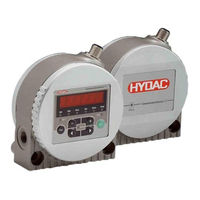
Hydac CS 1000 Series Operation And Maintenance Instructions (136 pages)
ContaminationSensor
Brand:
Hydac
| Category:
Accessories
| Size: 5 MB
Table of Contents
Imprint
2
Documentation Representative
2
Table of Contents
3
Content
3
Foreword
8
Technical Support
8
Modifications to the Product
8
Warranty
8
Using the Documentation
9
Safety Information
10
Hazard Symbols
10
Signal Words and Their Meaning in the Safety Information and Instructions
11
Structure of the Safety Information and Instructions
11
Observe Regulatory Information
12
Proper/Designated Use
12
Improper Use or Use Deviating from Intended Use
13
Qualifications of Personnel / Target Group
14
Storing the Sensor
16
Decoding the Type Label
16
Checking the Scope of Delivery
17
CS1000 Characteristics
18
Cs1X1X Dimensions (Without Display)
19
Cs1X2X Dimensions (with Display)
19
Fastening/Mounting the Sensor
20
Continuous Rotation of Sensor Display
21
Hydraulic Sensor Connection
22
Selecting Connection Type According to Sensor Type
23
Pipe or Hose Connection (Type Cs1Xxx-X-X-X-X-0/-XXX)
23
Flange Connection Type (Type Cs1Xxx-X-X-X-X-1/-XXX)
24
Selecting Measurement Location at the Hydraulic Systems
25
Flow Rate, Differential Pressure and Viscosity Characteristics
26
Connecting Hydraulic Sensor
27
Electrical Connection of Sensor
28
Pin Assignment
28
Connection Cable - Assignment / Color Coding
29
Connecting Cable Ends - Examples
30
Setting the Measuring Mode
31
Mode M1: Continuous Measurement
31
Mode M2: Continuous Measurement and Switching
31
Mode M3: Filter to Cleanliness Class and Stop
31
Mode M4: Filter to Continuously Monitor Cleanliness Class
32
Mode "SINGLE": Single Measurement
33
Operating the Cs1X2X Sensor Using the Keypad
34
Function of the Keys
35
Measured Variables on the Display
36
ISO (Cleanliness Class)
36
SAE (Cleanliness Class)
36
NAS (Cleanliness Class - CS 13Xx Only)
36
Service Variables on the Display
37
Flow (Flow Rate)
37
Out (Analogue Output)
37
Drive (Performance of the LED)
37
Temp (Temperature)
37
Activate / Deactivate Keypad Lock
38
Display Settings
38
Activating Display
39
Deactivating Display
40
Menus and Mode
40
Powerup Menu
41
Measuring Menu (Cs12Xx)
45
Display after Sensor Is Switched on
46
Configure Switching Output
47
M1 - Continuous Measurement
47
M2 - Continuous Measurement and Switching
47
M3 - Filter to Cleanliness Class and Stop
48
M4 - Filter to Continuously Monitor Cleanliness Class
48
Set Output Signal on Analogue Output
49
SINGLE - Start Single Measurement + Stop
49
Measuring Menu (CS 13Xx)
51
Display after Sensor Is Switched on
52
Configure Switching Output
53
M1 - Continuous Measurement
53
M2 - Continuous Measurement and Switching
53
M3 - Filter to Cleanliness Class and Stop
54
M4 - Filter to Continuously Monitor Cleanliness Class
55
SINGLE - Start Single Measurement + Stop
55
Set Output Signal on Analogue Output
56
Overview of Menu Structure
57
Menu CS 12Xx (ISO 4406:1999 and SAE)
57
Menu CS 13Xx (ISO 4406:1987 and NAS / ISO4406:1999 und SAE 4059)
59
Menu CS 13Xx (ISO 4406:1987 and NAS / ISO4406:1999 und SAE 4059)
61
Using Switching Output
63
Mode M1: Continuous Measurement
63
Mode M2: Continuous Measurement and Switching
63
Mode M3: Filter to Cleanliness Class and Stop
63
Mode M4: Filter to Continuously Monitor Cleanliness Class
63
Mode " ": Single Measurement
63
Setting Limit Values
64
Reading the Analog Output
66
SAE - Classes Acc. to as 4059
67
Sae A-D
69
SAE Classes a / B / C / D
70
Sae a / Sae B / Sae C / Sae D
71
Sae + T
72
HDA.SAE - Analog Signal SAE for HDA 5500
73
HDA.SAE Signal 1/2/3/4
74
HDA.SAE Signal 5 (Status)
75
ISO Code According to ISO 4406:1999
77
Iso 4 / Iso 6 / Iso 14
78
ISO Code, 3-Digit
79
Iso + T
80
HDA.ISO - Analog Signal ISO for HDA 5500
81
HDA.ISO Signal 1/2/3/4
82
HDA.ISO Signal 5 (Status)
83
ISOISO Code Signal Acc. to ISO 4406:1987 (CS 13Xx Only)
85
Iso 2 / Iso 5 / Iso 15
85
ISO Code, 3-Digit
87
Iso + T
88
HDA.ISO - Analog Signal ISO for HDA 5500
89
HDA.ISO Signal 1/2/3/4
90
HDA.ISO Signal 5 (Status)
91
NAS 1638 - National Aerospace Standard (CS 13Xx Only)
93
NAS Maximum
94
NAS Classes (2 / 5 / 15 / 25)
95
Nas 2 / Nas 5 / Nas 15 / Nas 25
96
Nas + T
97
HDA.NAS - Analog Signal NAS for HDA 5500
98
HDA.NAS Signal 1/2/3/4
99
HDA.NAS Signal 5 (Status)
100
Fluid Temperature TEMP
102
Status Messages
103
Status LED / Display
103
Error
106
Exceptions Errors
107
Analog Output Error Signals
109
Analog Signal for HDA 5500
110
HDA Status Signal 5 Table
110
Connecting CSI-D-5 (Condition Sensor Interface)
112
CSI-D-5 Connection Overview
112
Connecting the Sensor to a RS485 Bus
113
Reading out / Setting the Sensor Via the RS485 Bus
114
Evaluating/Reading Measurement Reports with Flumos
115
Performing Maintenance
116
Calibrating the Sensor
116
Cleaning the Display / User Interface
116
Decommissioning the Sensor
116
Disposing of the Sensor
116
Spare Parts and Accessories
117
Technical Data
118
Annex
120
Finding Customer Service
120
Germany
120
Usa
120
Australia
120
Brazil
121
China
121
Checking/Resetting Default Settings
122
Powerup Menu
122
Measuring Menu
122
Model Code
123
Cleanliness Classes - Brief Overview
124
Cleanliness Class - ISO 4406:1999
124
Overview of Modifications - ISO4406:1987 <-> ISO4406:1999
125
Cleanliness Class - SAE as 4059
126
Definition Acc. to SAE
127
Particle Count (Absolute) Larger than a Defined Particle Size
127
Specifying a Cleanliness Code for each Particle Size
127
Specifying Highest Measured Cleanliness Class
127
Cleanliness Class - NAS 1638
128
Egdeclaration of Conformity
129
Glossary
129
Explanation of Terms and Abbreviations
130
Displays
131
Index
132
Advertisement
HYDAC CS 1000 Series Operating And Maintenance Instructions Manual (78 pages)
Contamination Sensor
Brand:
HYDAC
| Category:
Accessories
| Size: 7 MB
Table of Contents
Table of Contents
5
Customer Service
10
1 General Safety Precautions
12
Obligations and Liability
12
Explanation of Symbols and Warnings, Etc
12
Basic Symbols
13
Proper/Designated Use
13
Improper Use
13
Safety Devices
13
Informal Safety Precautions
14
Instructions to be Followed in the Event of an Emergency
14
Training and Instruction of Personnel
15
Safety Measures to be Followed in Normal Operation
15
Electrical Hazards
15
Maintenance, Servicing and Troubleshooting
16
Modifications to the CS
16
Cleaning the CS and Disposal of the Media and Agents Used
16
2 Transportation, Packing, Storage
17
Transportation & Packing
17
Storage
17
Storage Conditions
17
3 Model Code / Product Identification
18
4 Scope of Delivery
19
5 Description
20
Restrictions Pertaining to the Use of the CS
20
Cs1X1X Dimensions (Without Display)
21
Cs1X2X Dimensions (with Display)
21
Connection Types
22
Pipe or Hose Connection Type (Cs1Xxx-X-X-X-X-0/-XXX)
22
Flange Connection Type (Cs1Xxx-X-X-X-X-1/-XXX)
22
6 Installation
23
Unpacking
23
Mechanical Mounting
23
Display Rotatable/Adjustable as Needed
24
Hydraulic Installation
25
Selection Guidelines for a Measurement Point
25
Flow Rate Q, Differential Pressure
26
P and Viscosity Ν Characteristics
26
Connect the CS to Your System as Follows
27
Electrical Installation
28
Block Diagram
28
Connection Cable (Accessories See Section 14)
28
Typical Wiring Diagram
29
7 Description of the Measuring Modes
30
Mode M1: Measure Continuously
30
Mode M2: Measure Continuously and Switch
30
Mode M3: Filter down to Contamination Level and Stop
30
Mode M4: Filter to Establish Contamination Levels Continuously
30
Mode M5: "SINGLE" Measurement
31
8 Operation
32
Display and Keypad Elements (Cs122X Only)
32
Key Lock
33
Modes and Menus
34
Power up Menu
34
Measuring Menu
35
Description of the Switching Output in the Measuring Modes
39
Mode M1: Measure Continuously
39
Mode M2: Measure Continuously and Switch
39
Mode M3: Filter down to Contamination Level and Stop
39
Mode M4: Filter to Establish Contamination Levels Continuously
39
Mode M5: Single Measurement
39
Switching Behavior of the Switching Output
40
9 Analog Output ( Anaout )
41
SAE Classes
41
SAE Signal Table
42
SAE A-D ( Saemax )
43
SAE Class a / B / C / D ( SAE )
43
Time-Coded Signal
43
4 - 20 Ma Signal
44
0 - 10 V Signal
45
Sae a / Sae B / Sae C / Sae D
46
Sae + T ( Sae+T )
46
4 - 20 Ma Signal
47
Time Coded Signal
47
0 - 10 V Signal
48
ISO Classes
49
ISO Signal Table
49
Iso 4 / Iso 6 / Iso 14
50
ISO Code ( ISO ), 3-Digit
50
Time-Coded Signal
50
4 - 20 Ma Signal
51
0 - 10 V Signal
52
Iso+T
52
Time-Coded Signal
52
4 - 20 Ma Signal
53
0 - 10 V Signal
54
Fluid Temperature ( TEMP )
55
Temperature Table
55
10 RS-485 Interface
57
11 Condition Sensor Interface (CSI-D-5)
58
Scope of Delivery
58
CSI-D-5 Connection Schematic
58
Power Adaptor Set-Up
59
12 Contamination Control Software 1000 (Cocos 1000)
60
General Remarks
60
System Requirements
60
Adaptor Box - Driver Installation
60
Installing Cocos 1000
62
Using Cocos 1000
65
Save Results Online
68
Troubleshooting
69
13 Removing the CS from the Hydraulic System
70
Disposal / Recycling and Decommissioning
70
14 Spare Parts and Accessories
70
15 ISO 4406 and SAE as 4059 Classes
71
Iso 4406:1999
71
ISO 4406 Table
71
Sae as 4059
72
SAE as 4059 Table
72
16 Status LED - Display / Error Codes
73
17 Factory Default Settings / Basic Settings
75
Power up Menu
75
Measuring Menu
75
18 Technical Data
76
19 Service
77
20 Model Code
78
Hydac CS 1000 Series Operating And Maintenance Instructions Manual (133 pages)
ContaminationSensor
Brand:
Hydac
| Category:
Accessories
| Size: 6 MB
Table of Contents
Grundlegende Sicherheitshinweise
11
Grundlegende Symbole
12
Informelle Sicherheitsmaßnahmen
13
Ausbildung des Personals
14
Wartung und Instandhaltung, Störungsbeseitigung
15
Transport, Verpackung, Lagerung
16
Typenschild / Produktidentifikation
17
Lieferumfang
18
Beschreibung
19
Cs1X1X Abmessungen (ohne Display)
20
Hydraulische Anschlussart
21
Installation
22
Display Stufenlos Drehbar
23
Hydraulische Installation
24
Verbinden des CS mit Ihrem System nach Folgenden Schritten
26
Elektrische Installation
27
Verkabelung Schema
28
Beschreibung der Messmodies
29
Mode M5: Einzelmessung
30
Modies und Menüs
31
Messmenü
33
Schaltverhalten des Schaltausganges in den Messmodies
36
Schaltverhalten am Schaltausgang
37
Signal Ausgang
38
SAE A-D (Saemax)
39
Zeitcodiertes Signal - I/SAE - Diagram
41
Zeitcodiertes Signal - I/ISO - Diagram
43
Analogausgang - I/ISO Tabelle
44
Analogausgang - I/Durchfluss Charakteristik
46
Analogausgang - I/Temperatur Charakteristik
48
Fehlermeldungen
49
Werkseinstellungen / Grundeinstellungen
50
Contaminationsensor Interface (CSI-D-5)
51
Einstellungen am Netzteil
52
Contamination Control Software 1000 (Cocos 1000)
53
HYDAC Filtertechnik Gmbh de Seite
55
Cocos 1000 Installation
56
Cocos 1000 Start
59
Datenspeicherung (Save Results)
63
Fehlerbehebung
64
ISO 4406 und SAE as 4059 Klassen
65
Sae as 4059
66
Entfernen des CS aus dem Hydraulik System / Außerbetriebnahme
67
Technische Daten
68
Kundendienst
69
Typenschlüssel
70
Customer Service
75
General Safety Precautions
77
Electrical Hazards
80
Electrical Installation
93
Block Diagram
93
Typical Wiring Diagram
94
Error Codes
113
System Requirements
117
Troubleshooting
126
Technical Data
130
Advertisement
Hydac CS 1000 Series Getting Started Manual (64 pages)
Brand:
Hydac
| Category:
Accessories
| Size: 9 MB
Table of Contents
Deutsch
3
Table of Contents
3
Lieferumfang Prüfen
4
Technische Daten
5
Abmessungen
7
Bestandteile
8
Transport und Lagerung
9
Montage, Installation und Inbetriebnahme
10
Display Drehen (nur Cs1X2X)
10
Sensor Montieren / Befestigen
10
Hydraulisch Anschließen
12
Gewindeanschluss (nur Cs1Xxx-X-X-X-X-0)
12
Flanschanschluss (nur Cs1Xxx-X-X-X-X-1)
12
Messstelle IM Hydrauliksystem Finden
13
Durchfluss, Differenzdruck und Viskosität Charakteristik
14
Elektrisch Anschließen
15
Sensor Hydraulisch Verbinden
15
Anschlusskabel / Verbindungskabel - Farbcodierung
16
Anschlussbeispiele
17
Inbetriebnahme
18
Betrieb
19
Display Ablesen / Tastatur Bedienen (nur Cs1X2X)
19
English
23
Checking the Scope of Delivery
24
Technical Data
25
Dimensions
27
Components
28
Transportation and Storage
29
Assembling / Fastening the Sensor
30
Assembly, Installation and Commissioning
30
Rotating the Display (Only Cs1X2X)
30
Connecting the Hydraulics
32
Flange Connection (Only Cs1Xxx-X-X-X-X-1)
32
Threaded Port (Only Cs1Xxx-X-X-X-X-0)
32
Finding the Measuring Point in the Hydraulic System
33
Flow Rate, Differential Pressure and Viscosity Characteristics
34
Electrical Connection
35
Hydraulic Connection of the Sensor
35
Single-Ended Cordset / Double-Ended Cordset - Color Coding
36
Connection Examples
37
Commissioning
38
Operation
39
Reading the Display / Operating the Keyboard (Only Cs1X2X)
39
Français
43
Contrôler le Contenu de la Livraison
44
Caractéristiques Techniques
45
Dimensions
47
Composants
48
Transport et Stockage
49
Montage, Installation et Mise en Service
50
Montage/Fixation du Capteur
50
Rotation de L'affichage (Uniquement Cs1X2X)
50
Raccord Fileté (Uniquement Cs1Xxx-X-X-X-X-0)
52
Raccord à Bride (Uniquement Cs1Xxx-X-X-X-X-1)
52
Raccordement Hydraulique
52
Trouver un Point de Mesure Dans le Système Hydraulique
53
Débit, Pression Différentielle et Viscosité - Caractéristique
54
Connexion Hydraulique du Capteur
55
Raccordement Électrique
55
Câble de Jonction/Câble de Connexion - Code Couleur
56
Exemples de Raccordement
57
Mise en Service
58
Lecture de L'écran/Utilisation du Clavier (Uniquement Cs1X2X)
59
Opération
59
Advertisement
Related Products
Hydac ContaminationSensor CS1220 VIMS
HYDAC CoCoS 1000
Hydac CS 2000 series
Hydac CSM 2000 series
Hydac CSI-B-1
Hydac CSI-C-11
Hydac CSI-Connect
Hydac CTU-1051-K-U-Z
Hydac CTU-1250-M-U-R
Hydac CTM-EF-1400-Z-Z-Z
HYDAC Categories
Water Filtration Systems
Industrial Equipment
Accessories
Control Unit
Switch
More HYDAC Manuals
Login
Sign In
OR
Sign in with Facebook
Sign in with Google
Upload manual
Upload from disk
Upload from URL