Blue Seal EVOLUTION Series Installation And Operation Manual
900/1200mm wide refrigeration base
Hide thumbs
Also See for EVOLUTION Series:
- Service manual (94 pages) ,
- Installation and operation manual (38 pages) ,
- Installation and operator's manual (28 pages)

Subscribe to Our Youtube Channel
Related Manuals for Blue Seal EVOLUTION Series


Summary of Contents for Blue Seal EVOLUTION Series
- Page 1 I N S T A L L A T I O N A N D O P E R A T I O N M A N U A L REFRIGERATION BASE Blue Seal RB900 - 900mm wide Refrigeration Base.
- Page 2 800 263 1455 (Toll Free) NEW ZEALAND Moffat Limited Web: www.moffat.co.nz E.Mail: sales@moffat.co.nz Main Office: (tel): 0800 663328 UNITED KINGDOM Blue Seal Web: www.blue-seal.co.uk E.Mail: sales@blue-seal.co.uk Sales: (tel): +44 121 327 5575 (fax): +44 121 327 9711 Spares: (tel): +44 121 322 6640...
-
Page 3: Table Of Contents
Contents Blue Seal - Refrigeration Base Blue Seal RB900 - 900mm wide Refrigeration Base. Blue Seal RB1200 - 1200mm wide Refrigeration Base. Introduction ....................3 Specifications ................... 4 Model Numbers Covered in this Specification XR02CX Controller SF-102 Controller General Electrical Supply Requirements Installation .................... - Page 4 Contents Cleaning and Maintenance ..............21 General Before Use Cleaning Weekly Cleaning Periods of Inactivity Periodic Maintenance Fault Finding .................... 23 Wiring Schematics ................... 25 Wiring Schematic XR02CX Controller Wiring Schematic SF-102 Controller Replacement Parts List ................27...
-
Page 5: Introduction
Introduction We are confident that you will be delighted with your BLUE SEAL REFRIGERATION BASE, and it will become a most valued appliance in your commercial kitchen. To ensure you receive the utmost benefit from your new Blue Seal Refrigeration Base, there are two important things you can do. -
Page 6: Specifications
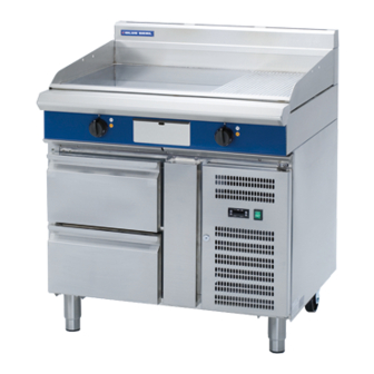
Model Numbers Covered in this Specification Blue Seal RB900 - 900mm wide Refrigeration Base. Blue Seal RB1200 - 1200mm wide Refrigeration Base. General A commercial heavy duty refrigeration base which can be used in conjunction with the Target Top, Cook Top and Dedicated Griddle appliances. -
Page 7: - Sf102 Controller
Specifications - SF102 Controller The controller is a mini-sized and integrated intelligent controller and applicable to the 1HP Compressor used on this Refrigeration Base. The main functions of the Controller are:- Temperature display. Temperature control. Manual / Automatic defrost. ... -
Page 8: Installation
Blue Seal Refrigeration Bases are designed to provide years of satisfactory service, and correct installation is essential to achieve the best performance, efficiency and trouble-free operation. -
Page 9: Assembly
Installation Assembly The dispersal of defrost water is done automatically with appliances fitted with integral condensing units. This appliance is fitted with adjustable feet to enable the unit to be positioned securely and level. This should be carried out on completion of the electrical connection. Electrical Connection NOTE: ALL ELECTRICAL FITTING MUST ONLY BE CARRIED OUT BY AN AUTHORISED PERSON. -
Page 10: Operation
Operation Operation Blue Seal Refrigerator Bases have been designed to provide simplicity of operation and 100% safety protection. Improper operation is therefore almost impossible, however bad operation practices can reduce the life of the appliance and produce poor results. To use this appliance correctly please read the following information carefully:- NOTE: The Refrigeration Base may be fitted with either of the following type controllers. -
Page 11: Operation - Xr02Cx Controller
Operation - XR02CX Controller Operation Guide - XR02XC Controller Only NOTE: Please ensure that the Controller shown below is the controller you have fitted to your appliance and ensure that you read the following operating instructions before using your appliance. Control Panel - Controller Defrost Defrost... -
Page 12: Operation Of The Controller
Operation - XR02CX Controller Operation of the Controller Main Power Switch Main Power Control switch for the power input to the Refrigeration Base and Control Panel. When switched 'ON', the switch is illuminated. Control Panel Functions The control panel includes the following keys and LED's; ... - Page 13 Operation - XR02CX Controller User Level Settings Parameter Range Default Settings Code Description Differential 0.1 ~ 25°C / 1 ~ 45°F 2°C / 35.6°F Minimum Set Point - 55°C ~ Set / -67°F ~ Set. -2°C / 28.4°F Maximum Set Point Set ~ 99°C / Set ~ 99°F.
-
Page 14: Operation Of The Appliance
Operation - XR02CX Controller Operation of the Appliance These Cabinets are activated by a main power switch and an electronic control panel. The operations available to the user are:- To Operate the Cabinet. a. Switch on the main power switch on the front of the appliance. b. -
Page 15: Controller Error Messages
Operation - XR02CX Controller Controller Error Messages Error messages are shown in the table below. Error Message Table Error Message Possible Cause Outputs Compressor output according to ‘Cy and ‘Cn’. ‘P1’ Cabinet Probe failure. ‘P2’ Evaporator Probe failure. Defrost end has timed out. ‘HA’... -
Page 16: Operation - Sf102 Controller
Operation - SF-102 Controller Operation Guide - SF102 Controller Only NOTE: Please ensure that the Controller shown below is the controller you have fitted to your appliance and ensure that you read the following operating instructions before using your appliance. Control Panel - Controller Compressor 'ON' Logo and Mains Power... -
Page 17: Function Of The Control Panel Keys
Operation - SF-102 Controller Function of the Control Panel Keys When depressed, while programming, will increase the value shown on the display:- For the Main Set-point configuration. For the Parameter configuration. When depressed, during normal controller operations, and held for 6 Seconds the evaporator temperature (detected by the cabinet end probe will be shown on the display). -
Page 18: Operation Of The Appliance
Operation - SF-102 Controller Operation of the Appliance These Cabinets are activated by a main power switch and an electronic control panel. The operations available to the user are:- To Operate the Cabinet. a. Switch on the main power switch on the front of the appliance. b. -
Page 19: Controller Error Messages
Operation - SF-102 Controller When setting Parameter F4, the cabinet temperature is locked during defrost and the last value before defrost will be displayed and the defrost LED will flash continuously. When the defrost is completed, the defrost LED will extinguish and normal display will resume, showing the current cabinet temperature. -
Page 20: Configuration Parameters And Default Settings
Operation - SF-102 Controller Configuration Parameters and Default Settings The configuration parameters and related limits (or options) are shown in the table below. Please note that to access these parameters through the Control Panel, the Key Pad will have to be unlocked to allow access to the Configuration Parameters. - Page 21 Operation - SF-102 Controller Changing the Configuration Parameters In the ‘Normal Operating Mode’, press the 'DOWN' key and hold for 10 seconds, the display will flash either ‘OFF’ (Lock) or ‘ON’ (Unlock) on the display. This either unlocks or locks the display. Ensure that the display is ‘Unlocked’...
- Page 22 Operation - SF-102 Controller Configuration Parameter Description # 1 - Main Setpoint; When the compressor is activated to decrease the cabinet temperature, this parameter sets the operating temperature of the cabinet, which must be set within the limits of parameters (E1) (Lower Limit) and (E2) (Upper Limit) below and which, when reached, will turn off the compressor.
-
Page 23: Cleaning And Maintenance
Cleaning and Maintenance General Caution Always turn ‘Off’ electrical supply before cleaning. This appliance is not water proof. Do not use water jet spray to clean interior or exterior of this appliance. To achieve the best results cleaning must be regular and thorough and all controls and mechanical parts checked and adjusted periodically by a competent serviceman. -
Page 24: Periods Of Inactivity
Cleaning and Maintenance Cleaning the Drawer Slides (Tracks) The stainless Steel drawer system including the drawer, intermediate tracks and exterior tracks should be kept free of food and debris. The intermediate tracks (the track containing all the rollers) are designed to be removable without tools and are dishwasher safe. They can also be cleaned in a sink with detergents and a soft bristle brush. -
Page 25: Fault Finding
Fault Finding Fault Finding Often, the malfunction of an appliance is due to simple causes which can easily be eliminated without contacting a technician. Simply follow the Fault Finding chart below. The ‘Fault Finding’ guide below covers all components having an active part in the control operation of the appliance and gives assistance to the most likely cause of failure should a fault develop. - Page 26 Fault Finding Fault Finding (Cont’d) Fault Possible Cause Remedy Cabinet unacceptably noisy. The cabinet has not been properly levelled. Re-level the cabinet using a spirit level. The framework has loose screws or bolts. Check the cabinet thoroughly and tighten any loose screws / bolts. Tubing vibration.
-
Page 27: Wiring Schematics
Wiring Schematic Wiring Schematics - XR02CX Controller Controller Wiring Connections Refrigeration Base Wiring Schematic Model:- RB1200 Compressor Power Plug Temperature Sensor Transformer Condenser Fan Motor... - Page 28 Wiring Schematic Wiring Schematics - SF-102 Controller Controller Wiring Connections Refrigeration Base Wiring Schematic...
-
Page 29: Replacement Parts List
Replacement Parts List Replacement Parts List IMPORTANT: Only genuine authorized replacement parts should be used for servicing and repair of this appliance. Instructions supplied with parts should be followed when replacing components. further information servicing instructions, contact your nearest authorized service branch (contact details are as shown on reverse of front cover of this manual).
Need help?
Do you have a question about the EVOLUTION Series and is the answer not in the manual?
Questions and answers