
Related Manuals for EKOM DK50 4VR/50 S/M


Summary of Contents for EKOM DK50 4VR/50 S/M
- Page 1 DK50 4VR/50/M DK50 2x4VR/110/M USER MANUAL BENUTZERHANDBUCH NÁVOD NA POUŽITIE...
- Page 3 COMPRESSOR DK50 4VR/50/M KOMPRESSOR DK50 2x4VR/110/M KOMPRESOR EKOM spol. s r. o. Priemyselná 5031/18 SK-921 01 Piešťany Slovak Republic tel.: +421 33 7967255 fax: +421 33 7967223 www.ekom.sk email: ekom@ekom.sk DATE OF LAST REVISION DATUM DER LETZTEN ÜBERARBEITUNG 03/2023 DÁTUM POSLEDNEJ REVÍZIE...
- Page 4 CONTENTS ....................5 INHALT ......................75 OBSAH ......................146...
-
Page 5: Table Of Contents
CONTENTS CONTENTS GENERAL INFORMATION ......................6 CONFORMITY WITH THE REQUIREMENTS OF THE EUROPEAN UNION ....6 SYMBOLS ........................6 DEVICE USE ........................7 GENERAL SAFETY INSTRUCTIONS ................8 STORAGE AND TRANSPORT CONDITIONS ..............9 PRODUCT DESCRIPTION ......................10 VARIANTS ........................10 ACCESSORIES ...................... -
Page 6: General Information
GENERAL INFORMATION GENERAL INFORMATION Carefully read this user manual before using the product and carefully store it for future reference. The user manual aids in the proper use, including installation, operation and maintenance, of the product. The user manual corresponds to the configuration of the product and its compliance with applicable safety and technical standards at the time of its printing. -
Page 7: Device Use
GENERAL INFORMATION Fuse Package handling label – fragile Package handling label – this side up Package handling label – keep dry Package handling label – temperature limits Package handling label – limited stacking Package label – recyclable material Manufacturer 3. DEVICE USE 3.1. -
Page 8: General Safety Instructions
GENERAL INFORMATION 4. GENERAL SAFETY INSTRUCTIONS The product is designed and manufactured so that any risks connected with its use are minimized and the product is safe for the user and surrounding when used according to the intended use and the instructions stated below are followed. -
Page 9: Storage And Transport Conditions
GENERAL INFORMATION 5. STORAGE AND TRANSPORT CONDITIONS The compressor is shipped from the manufacturer in transport packaging. This protects the product from damage during transport. Potential for damage to pneumatic components. The compressor must be transported only when all air has been vented. Before moving or transporting the compressor, release all the air pressure from the tank and pressure hoses and drain condensate from the tank and from the condensate separator on the dryer. -
Page 10: Product Description
6. VARIANTS The compressor is manufactured according to its intended application in the following variants: DK50 4VR/50/M Compressor with adsorption dryer. DK50 4VR/50 S/M Compressor in cabinet with adsorption dryer Cabinet S50R It decreases noise level of the compressor DK50 2x4VR/110/M... -
Page 11: Accessories
PRODUCT DESCRIPTION 7. ACCESSORIES Accessories that are not included in the standard order must be ordered separately. Set of compressed air outlet filters The compressor may be equipped with a set of filters if specified. The filter set may be equipped with an air pressure regulator. -
Page 12: Product Function
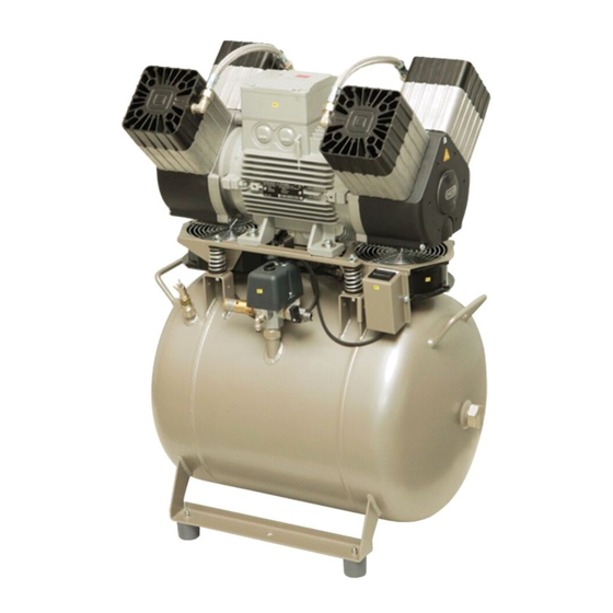
PRODUCT DESCRIPTION Compressor model Control schematic Article number System air outlet DK50 4VR/50/M G3/4“ 603002152-000 DK50 2x4VR/110/M 1+1+1 Equipotential bonding socket The socket allows an equipotential bonding Type Name Article number POAG-KBT6-EC Mains plug connector 033400075-000 DK50 4VR/50S/M DK50 2x4VR/110S/M FLEXI-S/POAG-HK6 Conductor (1m) 034110083-000... - Page 13 22 Regeneration solenoid valve Position (26) applies to the DK50 4VR/50/M, DK50 2x4VR/110/M model without the cabinet; position (26) in the case of the DK50 4VR/50 S/M, DK50 2x4VR/110 S/M with the cabinet is a simple cover. For the cabinet model, the cable connected to the display (33) in the front panel of the cabinet is routed through the universal bushing (37).
- Page 14 PRODUCT DESCRIPTION Fig. 1: DK50 4VR/50/M – Compressor with adsorption dryer NP-DK50 4VR50, DK50 2x4VR110-AD-A-6_03-2023 03/2023...
- Page 15 PRODUCT DESCRIPTION Fig. 2: DK50 2x4VR/110/M –Compressor with adsorption dryer 03/2023 NP-DK50 4VR50, DK50 2x4VR110-AD-A-6_03-2023...
- Page 16 Position (26) applies to the DK50 4VR/50/M, DK50 2x4VR/110/M model without the cabinet; position (26) in the case of the DK50 4VR/50 S/M, DK50 2x4VR/110 S/M with the cabinet is a simple cover. For the cabinet model, the cable connected to the display (33) in the front panel of the cabinet is routed through the universal bushing (37).
- Page 17 PRODUCT DESCRIPTION Fig. 4: Cabinet A - DK50 4VR/50S/M 03/2023 NP-DK50 4VR50, DK50 2x4VR110-AD-A-6_03-2023...
- Page 18 PRODUCT DESCRIPTION B - DK50 2x4VR/110S/M NP-DK50 4VR50, DK50 2x4VR110-AD-A-6_03-2023 03/2023...
-
Page 19: Technical Data
+5°C to +40°C Temperature Relative humidity max. 70% Working pressure 6 – 8 bar DK50 4VR/50/M DK50 4VR/50 S/M Nominal voltage, Frequency V, Hz 3x400, 50 3x400, 50 Capacity at 6 bar (FAD) l/min 6.0 – 8.0 6.0 –... - Page 20 TECHNICAL DATA Dependence of compressor output on working pressure NP-DK50 4VR50, DK50 2x4VR110-AD-A-6_03-2023 03/2023...
- Page 21 TECHNICAL DATA Working pressure 6 – 8 bar DK50 4VR/50/M DK50 4VR/50 S/M Nominal voltage, Frequency V, Hz 3x400, 50 3x400, 50 Capacity at 6 bar (FAD) l/min 6.0 – 8.0 6.0 – 8.0 Working pressure Rated current Motor power Air tank volume m...
- Page 22 TECHNICAL DATA Working pressure 8 – 10 bar DK50 4VR/50/M DK50 4VR/50 S/M Nominal voltage, Frequency V, Hz 3x400, 50 3x400, 50 Capacity at 8 bar (FAD) l/min 6.0 – 8.0 6.0 – 8.0 Working pressure Rated current Motor power Air tank volume m...
- Page 23 TECHNICAL DATA Working pressure 8 – 10 bar DK50 4VR/50/M DK50 4VR/50 S/M Nominal voltage, Frequency V, Hz 3x400, 50 3x400, 50 Capacity at 8 bar (FAD) l/min 6.0 – 8.0 6.0 – 8.0 Working pressure Rated current Motor power Air tank volume m...
- Page 24 TECHNICAL DATA Working pressure 6 – 8 bar DK50 2x4VR/110/M DK50 2x4VR/110S/M Nominal voltage, Frequency V, Hz 3x400V, 50Hz 3x400V, 50Hz Capacity at 6 bar (FAD) l/min 6.0 – 8.0 6.0 – 8.0 Working pressure Rated current 10.8 11.2 Motor power 2x2.2 2x2.2 Air tank volume...
- Page 25 TECHNICAL DATA Working pressure 6 – 8 bar DK50 2x4VR/110/M DK50 2x4VR/110S/M Nominal voltage, Frequency V, Hz 3x400V, 50Hz 3x400V, 50Hz Capacity at 6 bar (FAD) l/min 6.0 – 8.0 6.0 – 8.0 Working pressure Rated current 10.8 11.2 Motor power 2x2.2 2x2.2 Air tank volume...
- Page 26 TECHNICAL DATA Working pressure 8 – 10 bar DK50 2x4VR/110/M DK50 2x4VR/110S/M Nominal voltage, Frequency V, Hz 3x400V, 50Hz 3x400V, 50Hz Capacity at 8 bar (FAD) -20°C l/min 8.0 – 10.0 8.0 – 10.0 Working pressure Rated current 10.3 10.8 Motor power 2x2.2 2x2.2...
- Page 27 TECHNICAL DATA Working pressure 8 – 10 bar DK50 2x4VR/110/M DK50 2x4VR/110S/M Nominal voltage, Frequency V, Hz 3x400V, 50Hz 3x400V, 50Hz Capacity at 8 bar (FAD) l/min 8.0 – 10.0 8.0 – 10.0 Working pressure Rated current 10.3 10.8 Motor power 2x2.2 2x2.2 Air tank volume...
- Page 28 TECHNICAL DATA FAD correction of capacity for altitude Capacity given in the form of FAD („Free Air Delivery“) applies to the following conditions: 20°C Altitude 0 m.n.m. Temperature Atmospheric pressure 101325 Pa Relative humidity To calculate FAD compressor capacity in dependence on altitude, it is necessary to apply correction factor according to the following table: Altitude [m.n.m.] 0 -1500...
-
Page 29: Installation
INSTALLATION INSTALLATION Risk of incorrect installation. Only a qualified technician may install the compressor and place it into operation for the first time. Their duty is to train operating personnel on the use and maintenance of the equipment. An entry is made in the equipment installation record to certify installation and operator training. - Page 30 INSTALLATION The number of persons required to handle the equipment must be matched to the weight of the device. Fig. 5: Removing the transport mounts DK50 4VR/50 DK50 2x4VR/110 NP-DK50 4VR50, DK50 2x4VR110-AD-A-6_03-2023 03/2023...
- Page 31 INSTALLATION Fig. 6: Handling the compressor DK50 4VR/50 03/2023 NP-DK50 4VR50, DK50 2x4VR110-AD-A-6_03-2023...
- Page 32 INSTALLATION DK50 2x4VR/110 NP-DK50 4VR50, DK50 2x4VR110-AD-A-6_03-2023 03/2023...
- Page 33 INSTALLATION • Remove the mounts used to secure the aggregate in transport: use a 10 mm wrench to remove the upper bolts, and then use a 13 mm wrench to remove the lower side bolts (Fig. 7). Prior to installation, ensure that the compressor is free of all transport packaging and stabilizers to avoid any risk of damage to the product.
-
Page 34: Pneumatic Connection
INSTALLATION 11. PNEUMATIC CONNECTION 11.1. Connecting to the compressed air outlet • Route the pressure hose from the compressed air outlet (1) to the connected equipment. • A G 3/8" (DK50 4VR/50), G1/2" (DK50 2x4VR/110) connection is installed. • Route the pressure hose through the opening in the rear wall of the cabinet for cabinet- mounted compressors. - Page 35 INSTALLATION 11.3. Condensate outlet from dryer Injury hazard. Do not connect the condensate drain directly to a waste drain! Passers-by may be injured! • Connect a hose to the outlet (1) from the automatic condensate drain (2) to the provided collection vessel.
-
Page 36: Electrical Connection
INSTALLATION Risk of damage to pneumatic components. Air hoses must not be broken. 12. ELECTRICAL CONNECTION • The product is delivered with a cord equipped with a plug with earthing pin. • With cabinet-mounted compressors, route the power cord through the opening in the back wall of the cabinet. - Page 37 • Connect the display at the front door of the cabinet and then secure the cord to the display in the clamps (1). Secure the cord for DK50 4VR/50 S/M compressors in the clamp (1) in the cabinet door (Fig. 18). Secure the cord for DK50 2x4VR/110 S/M compressors in the clamps (1) in the cabinet enclosure (Fig.
-
Page 38: Placement Of The Compressor In The Cabinet
INSTALLATION 13. PLACEMENT OF THE COMPRESSOR IN THE CABINET 13.1. DK50 4VR/50 S/M (Fig. 4-A): Disassembly cabinet door • Remove the door held by 2 screws and disconnect the display connector and the earthing lead. Check to ensure the display connector is removed prior to removing the front door as otherwise it could be damaged. - Page 39 INSTALLATION Fig. 15: Positioning the compressor for electrical connections • Electrically connect the compressor per Chapter 12. • Insert the compressor into the cabinet using the positioning truck (35), place the connecting strip in front of the cabinet and adjust the position of the compressor so that the two “V” notches on the connecting strip (41) align with the compressor legs (Fig.
- Page 40 • Connect the earthing lead to the door and mount the door to the cabinet using 2 screws. Fig. 17: Connecting the display connector Fig. 18: DK50 4VR/50 S/M cabinet clamps 13.2. DK50 2x4VR/110 S/M (Fig. 4-B): Opening the upper cover •...
- Page 41 INSTALLATION Removal of the front panel on the cabinet • Remove the door held by 4 M5 screws and disconnect the display connector and the earthing lead. Check to ensure the display connector is removed prior to removing the front door as otherwise it could be damaged.
- Page 42 INSTALLATION Fig. 20: Positioning the compressor for electrical connections • Electrically connect the compressor per Chapter 12. • Insert the compressor with dryer into the cabinet so that the dryer fan fits into the cooling tunnel opening in the cabinet. Check the positioning of the compressor in the cabinet against Fig. 21. NP-DK50 4VR50, DK50 2x4VR110-AD-A-6_03-2023 03/2023...
- Page 43 INSTALLATION Fig. 21: Placement of the compressor in the cabinet • Connect the cabinet pressure gauge to the compressor per Chapter 11.2. Do not push the compressor all the way to the back of the cabinet as it may permanently damage the dryer. Front panel of the cabinet installation •...
-
Page 44: Commissioning
INSTALLATION Fig. 22: DK50 2x4VR/110 S/M cabinet clamps • Connect the earthing lead to the door. Install the door on the cabinet and mount using the 4 fasteners. 14. COMMISSIONING • Make sure all transport stabilizers were removed. • Check that all compressed air hose connections are correct. (see chap. 11) •... -
Page 45: Pneumatic And Electrical Diagrams
INSTALLATION 15. PNEUMATIC AND ELECTRICAL DIAGRAMS 15.1. Pneumatic diagram DK50 4V/50/M 03/2023 NP-DK50 4VR50, DK50 2x4VR110-AD-A-6_03-2023... - Page 46 INSTALLATION DK50 2x4VR/110/M Description to pneumatic diagram: Inlet filter Pressure gauge Air pump 10 Cooler 11 Cooler fan Safety valve 12 Air tank Non-return valve 13 Condensate drain valve Condensate separator 14 Outlet valve 15 Solenoid valve – regeneration Dryer 16 Solenoid valve –...
- Page 47 INSTALLATION 15.2. Electrical diagrams DK50 4VR/50/M 6 - 8 bar 3/N/PE~400V, 50Hz ELEKTRIC MAIN TN-S [TN-C-S] ELEKTRIC OBJECT OF 1st. CAT. 03/2023 NP-DK50 4VR50, DK50 2x4VR110-AD-A-6_03-2023...
- Page 48 INSTALLATION DK50 2x4VR/110/M 3/N/PE~400V, 50Hz ELEKTRIC MAIN TN-S [TN-C-S] ELEKTRIC OBJECT OF 1st. CAT. NP-DK50 4VR50, DK50 2x4VR110-AD-A-6_03-2023 03/2023...
- Page 49 INSTALLATION AD 280EK 1/N/PE ~ 230V/50Hz, 230V/60Hz ELEKTRIC OBJECT OF 1st. CAT AD500 1/N/PE~230V, 50/60Hz ~120V, 60Hz ELEKTRIC OBJECT OF 1st. CAT 03/2023 NP-DK50 4VR50, DK50 2x4VR110-AD-A-6_03-2023...
- Page 50 INSTALLATION Compressor cabinet 1/N/PE~230V, 50/60Hz ELEKTRIC OBJECT OF 1st. CAT. DK50 4VR/50S/M DK50 2x4VR/110S/M NP-DK50 4VR50, DK50 2x4VR110-AD-A-6_03-2023 03/2023...
- Page 51 INSTALLATION Description to electrical diagrams: M1, M2 Compressor motor Socket E1 – E4 Compressor fan Service indicator socket Fuse Switch F1, F2 Breaker X10,X11 Connector Pressure switch E10, E11 Cabinet fan Temperature switch E6-E8 Dryer fan Q11,12 Contactor M11, M13 Solenoid valve - regeneration Time relay Solenoid valve - venting...
-
Page 52: Operation
OPERATION OPERATION ONLY TRAINED PERSONNEL MAY OPERATE THE EQUIPMENT! Risk of electric shock. In case of emergency, disconnect the compressor from the mains (pull out the mains plug). Burn or fire hazard. Portions of the aggregate and compressed air components between the aggregate and dryer may be hot and reach hazardous temperatures during compressor operation that may harm materials or operating staff. -
Page 53: Switching On The Compressor
OPERATION 16. SWITCHING ON THE COMPRESSOR Start the compressor (without a cabinet) at the pressure switch (1) by turning the switch (2) to position “I.” This starts the compressor and fills the tank to the switching off pressure, which then shuts off the compressor. -
Page 54: Ad Dryer
AD DRYER AD DRYER 18. PRINCIPLE OF OPERATION The dryer is controlled by a signal from the compressor pressure switch. When the compressor is running, compressed air enters the cooler where it is cooled, and a portion of the condensed moisture is separated in the integrated cyclical separator. Solenoid valve V3 is located in the bottom of the separator, and it drains off the condensate from the separator at regular intervals. -
Page 55: User Interface / Settings
AD DRYER range of a visual warning signal depending on actual operating conditions. Low pressure. This signal is active when the dryer pressure sensor reads low pressure in the dryer under the defined limit of 3 bar. An air leak from the compressor/dryer, malfunction of the control solenoid valves on the dryer or a software error may activate this alarm during operation. - Page 56 AD DRYER Symbol for chamber pre-filling – equalisation of pressure in chambers. Indication the device is operating Indication of an alarm state (on until the alarm state no longer exists) 19.2. Initial settings for the user interface The option to select language, time and date appears when the program is first launched. The service technician selects the given language, time and date during installation based on the geographic location of the dryer installation.
-
Page 57: Main Screens
AD DRYER 19.4. Setting the drying mode during commissioning It is recommended to set the air-drying mode during commissioning. These settings are changed in the service menu in the SERVICE SETUP section. Access to the service menu is protected by a code. - Page 58 AD DRYER Basic information and measured parameters are shown on the dryer home screen. The dryer operating hours indicator is located at the top of the screen. The home screen has 4 main tiles that display the following information: Dryer operating mode (see chap.19.1) Current pressure in the dryer (min.
-
Page 59: Indication Of Maintenance And Alarm States
AD DRYER 20.4. Service menu screen The service menu is intended exclusively for service personnel. Access to individual menu items is password (1992) protected. 21. INDICATION OF MAINTENANCE AND ALARM STATES The adsorption dryer controller is capable of measuring selected parameters (pressure and pressure dew point in versions with a dew point sensor) and for assessing the basic dryer operating states. - Page 60 AD DRYER 21.3. Alarm conditions Low / high pressure • A red warning is shown (“Warning!”) if low pressure (<3 bar) or high pressure (> 8.5 bar, or > 10.5 bar depending on the pressure version) is detected. At the same time, the current pressure tile lights up red.
-
Page 61: Product Maintenance
PRODUCT MAINTENANCE PRODUCT MAINTENANCE 22. PRODUCT MAINTENANCE The operator should carry out device checks regularly in the intervals defined by applicable regulations. Test results must be recorded. The equipment has been designed and manufactured to keep maintenance to a minimum. The following work must be performed to preserve the proper and reliable operation of the compressor. - Page 62 PRODUCT MAINTENANCE 22.1. Maintenance intervals Performed operator qualified technician Set of replacement parts Chap. 24 000 h 20 000 h 16 000 h 12 000 h 10 000 h 8 000 h 6 000 h 4 000 h 2 000 h Once every 6 years Once every...
- Page 63 PRODUCT MAINTENANCE Performed qualified technician Set of replacement parts Chap. 24 000 h 20 000 h 16 000 h 12 000 h 10 000 h 8 000 h 6 000 h 4 000 h 2 000 h Once every 6 years Once every 4 years Once every...
- Page 64 PRODUCT MAINTENANCE 22.2. Check of product operation • Check air pump condition – the air pumps should be operating normally without excessive vibration or noise. Troubleshoot any problem or call in service personnel if trouble is detected. • Visually inspect fan operation – the fans must be operating when the air pumps are running. Troubleshoot any problem or call in service personnel if trouble is detected.
- Page 65 PRODUCT MAINTENANCE • Visually check if cables are connected to the terminal box. • Check all screw connections of the green-yellow PE grounding conductor. 22.5. Condensate drain A wet floor resulting from overflow from the vessel poses a slip hazard. Regularly empty the condensate collection vessel.
- Page 66 PRODUCT MAINTENANCE Before the following checks it is required: • For compressor variant with cabinet – unlock the door lock and open the cabinet door. 22.6. Check of safety valve • Turn the screw (2) on the safety valve (1) several times to the left until the safety valve releases the air.
- Page 67 PRODUCT MAINTENANCE 22.8. Procedure for connecting a compressor disconnected from the cabinet Prior to any maintenance or repair work, switch off the compressor and disconnect it from the mains (pull out the mains plug). The compressor (without cabinet) requires that the jumper is always mounted in the terminal strip for correct operation (Fig.
- Page 68 PRODUCT MAINTENANCE Fig. 27: DK50 4VR/50/M 400V NP-DK50 4VR50, DK50 2x4VR110-AD-A-6_03-2023 03/2023...
- Page 69 PRODUCT MAINTENANCE Fig. 28: DK50 2x4VR/110/M 400 V 22.9. Procedure for connecting a compressor to a new cabinet Prior to any maintenance or repair work, switch off the compressor and disconnect it from the mains (pull out the mains plug). The compressor in a cabinet requires that the jumper is not mounted in the terminal strip for correct operation (Fig.
- Page 70 PRODUCT MAINTENANCE If there is a jumper in the terminal strip of the compressor connected to a cabinet, the switch on the compressor cabinet will not work! If we want to connect a new cabinet to a compressor that previously worked alone (a compressor without a cabinet), then it is necessary to cancel the connection in the compressor terminal strip by performing the procedure, see further.
-
Page 71: Long-Term Shutdown
PRODUCT MAINTENANCE Sensor calibration ordering process: • Visit the website www.vaisala.com, and then navigate to the Services section and select Calibration and repair services. • Then enter the type of sensor (sensor type: DMT143) and select a calibration type, then follow the provided instructions. -
Page 72: Troubleshooting
TROUBLESHOOTING TROUBLESHOOTING Risk of electric shock. Before interfering with the equipment, first disconnect it from the mains (remove the power socket). Working with pressurised pneumatic components poses a risk of injury. Before interfering with the equipment, vent the air tank and the compressed air system to zero pressure. - Page 73 TROUBLESHOOTING Damaged piston bearing, piston Replace damaged bearing Compressor is rods, motor bearing noisy (knocking, Loose (cracked) dampening metal noises) Replace damaged spring element (spring) Replace fan Defective cooler fan Check power source Dryer does not dry (condensed water Damaged dryer Replace dryer in the air) * Defective automatic condensate...
-
Page 74: Repair Service
TROUBLESHOOTING Check the moisture content of the air exiting the air tank (see the Technical data chapter) to prevent damage to connected downstream equipment. 25. REPAIR SERVICE Warranty and post-warranty repairs must be done by the manufacturer, its authorized representative, or service personnel approved by the supplier. Attention. - Page 75 INHALT INHALT ALLGEMEINE INFORMATIONEN ....................76 KONFORMITÄT MIT DEN ANFORDERUNGEN DER EU ..........76 SYMBOLE ........................76 NUTZUNG DES GERÄTS ....................77 ALLGEMEINE SICHERHEITSANWEISUNGEN ............. 78 LAGERUNGS- UND TRANSPORTBEDINGUNGEN ............79 PRODUKTBESCHREIBUNG ....................... 80 VERSIONEN ........................80 ZUBEHÖR ........................81 PRODUKTFUNKTION ....................
-
Page 76: Allgemeine Informationen
ALLGEMEINE INFORMATIONEN ALLGEMEINE INFORMATIONEN Lesen Sie das Benutzerhandbuch vor der Nutzung des Produkts sorgfältig durch und bewahren Sie es auf. Das Benutzerhandbuch enthält Anleitungen zur korrekten Nutzung, Installation, Bedienung und Wartung des Produkts. Zum Zeitpunkt des Drucks entspricht das Benutzerhandbuch dem Produktdesign und erfüllt die geltenden Sicherheits- und Technikstandards. -
Page 77: Nutzung Des Geräts
ALLGEMEINE INFORMATIONEN Schutzerdung Sicherung Etikett für die Handhabung der Verpackung – zerbrechlich Etikett für die Handhabung der Verpackung – diese Seite nach oben Etikett für die Handhabung der Verpackung – trocken lagern Etikett für die Handhabung der Verpackung – Temperaturgrenzwerte Etikett für die Handhabung der Verpackung –... -
Page 78: Allgemeine Sicherheitsanweisungen
ALLGEMEINE INFORMATIONEN unsachgemäße Nutzung oder durch die Nichtbeachtung der Anweisungen in diesem Benutzerhandbuch. Einzig der Benutzer/Bediener trägt alle Risiken. 4. ALLGEMEINE SICHERHEITSANWEISUNGEN Das Produkt wurde entwickelt und hergestellt, um alle Risiken in Verbindung mit seiner Nutzung zu minimieren. Das Produkt ist für den Benutzer und die Umgebung sicher, wenn es gemäß seinem Verwendungszweck und den nachfolgend aufgeführten Anweisungen verwendet wird. -
Page 79: Lagerungs- Und Transportbedingungen
ALLGEMEINE INFORMATIONEN 5. LAGERUNGS- UND TRANSPORTBEDINGUNGEN Der Kompressor wird ab Hersteller in einer Transportverpackung versendet. Diese schützt das Produkt während des Transports vor Schäden. Beschädigungsgefahr für Pneumatikkomponenten! Der Kompressor darf nur transportiert werden, wenn die gesamte Luft abgelassen wurde. Vor dem Bewegen oder Transportieren des Kompressors entlassen Sie jegliche Druckluft aus dem Behälter und den Druckschläuchen und lassen Sie das Kondensat aus dem Behälter und dem Kondensatabscheider am Trockner ab. -
Page 80: Produktbeschreibung
PRODUKTBESCHREIBUNG PRODUKTBESCHREIBUNG 6. VERSIONEN Der Kompressor ist gemäß seinem Verwendungszweck in den folgenden Modellen erhältlich: DK50 4VR/50/M Kompressor mit Adsorptionstrockner Kompressor im Gehäuse mit Adsorptionstrockner DK50 4VR/50S/M Gehäuse S50R Reduziert den Geräuschpegel des Kompressors DK50 2x4VR/110/M Kompressor mit Adsorptionstrockner Kompressor im Gehäuse mit Adsorptionstrockner DK50 2x4VR/110S/M Gehäuse S110R Reduziert den Geräuschpegel des Kompressors... -
Page 81: Zubehör
PRODUKTBESCHREIBUNG 7. ZUBEHÖR Zubehör, das nicht Teil des Lieferumfangs ist, muss separat bestellt werden. Satz mit Druckluft-Ausgangsfiltern Der Kompressor kann, sofern angegeben, mit einem Filtersatz ausgestattet werden. Der Filtersatz kann mit einem Druckluftregler ausgestattet werden. Ist ein anderer Grad an Luftfilterung nötig, muss dies mit dem Lieferanten vereinbart und in der Bestellung klar angegeben werden. -
Page 82: Produktfunktion
PRODUKTBESCHREIBUNG übernimmt der Regler im Modul die Schaltfunktion des Kompressors. Das Steuermodul kann mit den in der folgenden Tabelle dargestellten Konfigurationen bestellt werden. Artikelnummer des Luftauslass des Kompressormodell Steuerschema Einbausatzes Systems DK50 4VR/50/M G3/4“ 603002152-000 DK50 2x4VR/110/M 1+1+1 Potenzialausgleichsbuchse Die Buchse ermöglicht einen Potenzialausgleich. Verwendung Name Artikelnummer... - Page 83 PRODUKTBESCHREIBUNG Beschreibung für Abbildungen 1 - 3 22 Regenerationsmagnetventil Luftpumpe 23 Trocknerlüfter Druckluftbehälter 24 Kondensatabscheider Rückschlagventil 25 Kondensatablassmagnetventil Druckschalter 26 *Trocknerdisplay Sicherheitsventil 27 Druckluftausgang Manometer 28 Gehäuselüfter Ablassventil 29 Gehäuse-Druckmesser Ansaugfilter 30 Schalter Adsorptionstrockner 31 Gehäuseverbinder 10 Kompressorlüfter 32 Manometer-Schlauch 11 Kondensatauffangbehälter 33 Gehäusedisplay 12 Magnetische Halterung...
- Page 84 PRODUKTBESCHREIBUNG Abb. 1: DK50 4VR/50/M – Kompressor mit Adsorptionstrockner NP-DK50 4VR50, DK50 2x4VR110-AD-A-6_03-2023 03/2023...
- Page 85 PRODUKTBESCHREIBUNG Abb. 2: DK50 2x4VR/110/M – Kompressor mit Adsorptionstrockner 03/2023 NP-DK50 4VR50, DK50 2x4VR110-AD-A-6_03-2023...
- Page 86 Position (26) gilt für das Modell DK50 4VR/50/M, DK50 2x4VR/110/M ohne Schrank; Position (26) beim DK50 4VR/50 S/M, DK50 2x4VR/110 S/M mit Schrank ist eine einfache Abdeckung. Bei der Schrankausführung wird das mit dem Display (33) in der Vorderseite des Schranks verbundene Kabel durch die Universalbuchse (37) geführt.
- Page 87 PRODUKTBESCHREIBUNG Abb. 4: Gehäuse A – DK50 4VR/50S/M 03/2023 NP-DK50 4VR50, DK50 2x4VR110-AD-A-6_03-2023...
- Page 88 PRODUKTBESCHREIBUNG B – DK50 2x4VR/110S/M NP-DK50 4VR50, DK50 2x4VR110-AD-A-6_03-2023 03/2023...
-
Page 89: Technische Daten
Bedingungen vorgesehen: +5 °C bis +40 °C Temperatur Relative Feuchtigkeit max. 70 % Arbeitsdruck 6 – 8 bar DK50 4VR/50/M DK50 4VR/50 S/M Nennspannung, Frequenz V, Hz 3x400, 50 3x400, 50 Kapazität bei 6 bar (FAD) l/min 6,0 –... - Page 90 TECHNISCHE DATEN Abhängigkeit von Kompressorkapazität und Arbeitsdruck NP-DK50 4VR50, DK50 2x4VR110-AD-A-6_03-2023 03/2023...
- Page 91 TECHNISCHE DATEN Arbeitsdruck 6 – 8 bar DK50 4VR/50/M DK50 4VR/50 S/M Nennspannung, Frequenz V, Hz 3x400, 50 3x400, 50 Kapazität bei 6 bar (FAD) l/min 6,0 – 8,0 6,0 – 8,0 Arbeitsdruck Nennstrom Motorleistung Volumen Drucklufttank m Luftqualität – Filterung Max.
- Page 92 TECHNISCHE DATEN Arbeitsdruck 8 – 10 bar DK50 4VR/50/M DK50 4VR/50 S/M Nennspannung, Frequenz V, Hz 3x400, 50 3x400, 50 Kapazität bei 8 bar (FAD) l/min 8,0 – 10,0 8,0 – 10,0 Arbeitsdruck Nennstrom Motorleistung Volumen Drucklufttank m Luftqualität – Filterung Max.
- Page 93 TECHNISCHE DATEN Arbeitsdruck 8 – 10 bar DK50 4VR/50/M DK50 4VR/50 S/M Nennspannung, Frequenz V, Hz 3x400, 50 3x400, 50 Kapazität bei 8 bar (FAD) l/min 8,0 – 10,0 8,0 – 10,0 Arbeitsdruck Nennstrom Motorleistung Volumen Drucklufttank m Luftqualität – Filterung Max.
- Page 94 TECHNISCHE DATEN Arbeitsdruck 6 bis 8 bar DK50 2x4VR/110/M DK50 2x4VR/110S/M Nennspannung, Frequenz V, Hz 3x400V, 50Hz 3x400V, 50Hz Kapazität bei 6 bar (FAD) l/min 6,0 – 8,0 6,0 – 8,0 Arbeitsdruck Nennstrom 10,8 11,2 Motorleistung 2x2.2 2x2.2 Volumen Drucklufttank m Luftqualität –...
- Page 95 TECHNISCHE DATEN Arbeitsdruck 6 bis 8 bar DK50 2x4VR/110/M DK50 2x4VR/110S/M Nennspannung, Frequenz V, Hz 3x400V, 50Hz 3x400V, 50Hz Kapazität bei 6 bar (FAD) l/min 6,0 – 8,0 6,0 – 8,0 Arbeitsdruck Nennstrom 10,8 11,2 Motorleistung 2x2.2 2x2.2 Volumen Drucklufttank m Luftqualität –...
- Page 96 TECHNISCHE DATEN Arbeitsdruck 8 bis 10 bar DK50 2x4VR/110/M DK50 2x4VR/110S/M Nennspannung, Frequenz V, Hz 3x400V, 50Hz 3x400V, 50Hz Kapazität bei 8 bar (FAD) l/min 8,0 – 10,0 8,0 – 10,0 Arbeitsdruck Nennstrom 10,3 10,8 Motorleistung 2x2.2 2x2.2 Volumen Drucklufttank m Luftqualität –...
- Page 97 TECHNISCHE DATEN Arbeitsdruck 8 bis 10 bar DK50 2x4VR/110/M DK50 2x4VR/110S/M Nennspannung, Frequenz V, Hz 3x400V, 50Hz 3x400V, 50Hz Kapazität bei 8 bar (FAD) l/min 8,0 – 10,0 8,0 – 10,0 Arbeitsdruck Nennstrom 10,3 10,8 Motorleistung 2x2.2 2x2.2 Volumen Drucklufttank m Luftqualität –...
- Page 98 TECHNISCHE DATEN FAD-Kapazitätskorrektur für Höhenlagen Die Kapazität in Form von FAD („Free Air Delivery“ = Volumenstrom bzw. Liefermenge) gilt für die folgenden Bedingungen: Höhenlage 0 m ü. M. 20 °C Temperatur Umgebungsdruck 101325 Pa Relative Feuchtigkeit Um die FAD-Kompressorkapazität in Abhängigkeit von der Höhenlage zu berechnen, muss der Korrekturfaktor gemäß...
-
Page 99: Installation
INSTALLATION INSTALLATION Risiko von Installationsfehlern Der Kompressor darf nur durch einen hierfür qualifizierten Techniker installiert und in Betrieb genommen werden. Dieser ist verpflichtet, professionelles Bedienpersonal bzgl. der Nutzung und Wartung der Gerätschaften zu schulen. Für den Nachweis einer Installations- und Bedienerschulung erfolgt ein Eintrag in das Installationsprotokoll der Gerätschaft. - Page 100 INSTALLATION Verwenden Sie die Griffe am Kompressor, um ihn bei Bedarf zu bewegen. Verwenden Sie keine anderen Teile des Kompressors (das Aggregat, den Kühler usw.) als Griff. Die Anzahl der Personen, die zum Umgang mit dem Gerät erforderlich sind, muss auf das Gewicht des Geräts abgestimmt sein.
- Page 101 INSTALLATION Abb. 6: Handhabung des Kompressors DK50 4VR/50 03/2023 NP-DK50 4VR50, DK50 2x4VR110-AD-A-6_03-2023...
- Page 102 INSTALLATION DK50 2x4VR/110 NP-DK50 4VR50, DK50 2x4VR110-AD-A-6_03-2023 03/2023...
- Page 103 INSTALLATION • Entfernen Sie die Halterungen zur Transportsicherung des Aggregats: Entfernen Sie mit einem oberen Schrauben dann einem 13-mm- 10-mm-Schraubenschlüssel Schraubenschlüssel die unteren seitlichen Schrauben (Abb. 7). Stellen Sie vor der Installation sicher, dass der Kompressor frei von Verpackungsmaterial und Stabilisatoren ist, um Schäden am Produkt zu vermeiden.
-
Page 104: Pneumatischer Anschluss
INSTALLATION 11. PNEUMATISCHER ANSCHLUSS 11.1. Anschluss an den Druckluftausgang • Führen Sie den Druckluftschlauch vom Druckluftausgang (1) zur angeschlossenen Gerätschaft. • A-G-3/8" (DK50 4VR/50), G1/2" (DK50 2x4VR/110)-Verbindung ist installiert. • Führen Sie den Druckschlauch bei Kompressoren mit Schrankmontage durch die Öffnung an der Rückwand des Schranks. - Page 105 INSTALLATION 11.3. Kondensatablass vom Trockner Verletzungsgefahr. Verbinden Sie den Kondensatablauf nicht direkt mit einem Abfluss! Passanten können verletzt werden! • Schließen Sie einen Schlauch an Auslass (1) des automatischen Kondensatablaufs (2) an den bereitgestellten Sammelbehälter an. • Führen Sie bei einem Kompressor in einem Schrank den Schlauch durch die hintere Öffnung im Schrank.
-
Page 106: Elektrischer Anschluss
INSTALLATION Beschädigungsgefahr für Pneumatikkomponenten! Druckluftschläuche müssen unbeschädigt sein. 12. ELEKTRISCHER ANSCHLUSS • Das Produkt wird mit einem Kabel mit Stecker und Erdungsstift geliefert. • Führen Sie bei im Gehäuse montierten Kompressoren das Stromkabel durch die Öffnung in der Rückwand des Gehäuses. •... -
Page 107: Platzierung Des Kompressors Im Gehäuse
• Schließen Sie das Display an der Fronttür des Schranks an, befestigen Sie dann das Kabel am Display in den Klemmen (1). Befestigen Sie das Kabel für DK50 4VR/50 S/M-Kompressoren in der Klemme (1) in der Schranktür (Abb. 18). Befestigen Sie das Kabel für DK50 2x4VR/110 S/M-Kompressoren in den Klemmen (1) im Schrankgehäuse (Abb. - Page 108 INSTALLATION Kompressoreinbau • Entfernen Sie die Anschlussleiste (41) vor dem Schrank. • Positionieren Sie den Kompressor in einem Abstand von mindestens 500 mm vom Schrank, um die Bewegung der Schläuche und des Netzkabels im Schrank zu ermöglichen (Abb. 14). Abb. 14: Positionierung des Kompressors für Anschlüsse •...
- Page 109 INSTALLATION • Schließen Sie den Kompressor gemäß Kapitel 12 an die Stromversorgung an. • Setzen Sie den Kompressor mithilfe des Positionierungsrollwagens (35) in das Gehäuse ein, platzieren Sie die Anschlussleiste vor dem Gehäuse und justieren Sie die Position des Kompressors so, dass die beiden „V“-Nuten der Anschlussleiste (41) an den Kompressorfüßen ausgerichtet sind (Abb.
- Page 110 INSTALLATION Abb. 17: Anschließen des Displaysteckers Abb. 18: Schrankklemmen DK50 4VR/50 S/M NP-DK50 4VR50, DK50 2x4VR110-AD-A-6_03-2023 03/2023...
- Page 111 INSTALLATION 13.2. DK50 2x4VR/110S/M (Abb. 4-B): Öffnen der oberen Abdeckung • Heben Sie die obere Gehäuseabdeckung an, indem Sie den Griff (42) in die Hand nehmen, sodass die Gasfeder die Abdeckung geöffnet hält. Achten Sie beim Schließen der Abdeckung am Gehäuse darauf, sich nicht die Finger einzuklemmen.
- Page 112 INSTALLATION Abb. 20: Positionierung des Kompressors für elektrische Anschlüsse • Schließen Sie den Kompressor gemäß Kapitel 12 an die Stromversorgung an. • Setzen Sie den Kompressor mit einem Trockner in den Schrank ein, sodass der Trocknerventilator in die Öffnung des Kühltunnels im Schrank passt. Überprüfen Sie die Positionierung des Kompressors im Schrank anhand Abb.
- Page 113 INSTALLATION Abb. 21: Platzierung des Kompressors im Gehäuse • Verbinden Sie den Gehäuse-Druckmesser gemäß Kapitel 11.2 mit dem Kompressor. Schieben Sie den Kompressor nicht ganz bis zur Rückseite des Schranks, da dadurch der Trockner dauerhaft beschädigt werden kann. Installation der Frontabdeckung des Schranks •...
-
Page 114: Inbetriebnahme
INSTALLATION Abb. 22: Schrankklemmen DK50 2x4VR/110 S/M • Verbinden Sie den Erdungsdraht an der Tür an. Bringen Sie die Tür am Schrank an und befestigen Sie sie mit den 4 Befestigungselementen. 14. INBETRIEBNAHME • Stellen Sie sicher, dass alle Transporthilfen entfernt wurden. •... -
Page 115: Druckluft- Und Elektroschaltpläne
INSTALLATION 15. DRUCKLUFT- UND ELEKTROSCHALTPLÄNE 15.1. Druckluftplan DK50 4V/50/M 03/2023 NP-DK50 4VR50, DK50 2x4VR110-AD-A-6_03-2023... - Page 116 INSTALLATION DK50 2x4VR/110/M Beschreibung des Druckluftplans: Manometer Ansaugfilter 10 Kühler Kompressor 11 Kühlerlüfter Lüfter 12 Druckluftbehälter Sicherheitsventil 13 Ablassventil Rückschlagventil 14 Ausgangsventil Kondensatabscheider 15 Regenerationsmagnetventil Trockner 16 Kondensatablassventil Druckschalter 17 Kondensatauffangbehälter NP-DK50 4VR50, DK50 2x4VR110-AD-A-6_03-2023 03/2023...
- Page 117 INSTALLATION 15.2. Elektroschaltpläne DK50 4VR/50/M 6 - 8 bar 3/N/PE~400V, 50Hz NETZ TN-S [TN-C-S] ELEKTRISCHES OBJEKT 1. KAT. 03/2023 NP-DK50 4VR50, DK50 2x4VR110-AD-A-6_03-2023...
- Page 118 INSTALLATION DK50 2x4VR/110/M 6 - 8 bar, 8 - 10 bar 3/N/PE~400V, 50Hz NETZ TN-S [TN-C-S] ELEKTRISCHES OBJEKT 1. KAT. NP-DK50 4VR50, DK50 2x4VR110-AD-A-6_03-2023 03/2023...
- Page 119 INSTALLATION AD 280EK 1/N/PE ~ 230V/50Hz, 230V/60Hz ELEKTRISCHES OBJEKT 1. KAT. AD500 1/N/PE~230V, 50/60Hz ~120V, 60Hz ELEKTRISCHES OBJEKT 1. KAT. 03/2023 NP-DK50 4VR50, DK50 2x4VR110-AD-A-6_03-2023...
- Page 120 INSTALLATION Kompressorgehäuse 1/N/PE ~ 230V 50/60Hz ELEKTRISCHES OBJEKT 1. KAT. DK50 4VR/50 S/M DK50 2x4VR/110 S/M NP-DK50 4VR50, DK50 2x4VR110-AD-A-6_03-2023 03/2023...
- Page 121 INSTALLATION Beschreibung der Elektroschaltpläne: M1, M2 Kopresormotor Buchse E1 – E4 Kompressorlüfter Serviceanzeigebuchse Sicherung Schalter F1, F2 Ausschalter X10,X11 Verbinder Gehäuselüfter Druckschalter E10, E11 Trocknerlüfter Temperaturschalter E6-E8 Schütz Q11,12 M11, M13 Regenerationsmagnetventil Magnetventil – Entlüftung Zeituhr-Relais Stundenzähler RSA 10 Steuerung Klemmblock 03/2023 NP-DK50 4VR50, DK50 2x4VR110-AD-A-6_03-2023...
-
Page 122: Betrieb
BETRIEB BETRIEB DAS GERÄT DARF NUR DURCH GESCHULTES PERSONAL BEDIENT WERDEN! Stromschlaggefahr! Bei Gefahr den Kompressor vom Stromnetz trennen (Netzstecker ziehen)! Verbrennungs- oder Brandgefahr! Teile des Aggregats und der Druckluftkomponenten zwischen dem Aggregat und dem Trockner können während des Betriebs heiß werden und gefährliche Temperaturen erreichen, die die Materialien schädigen oder das Bedienpersonal verletzen können. -
Page 123: Einschalten Des Kompressors
BETRIEB 16. EINSCHALTEN DES KOMPRESSORS Starten Sie den Kompressor (ohne Gehäuse) am Druckschalter (1), indem Sie den Schalter (2) auf Position „I“ stellen. Dadurch wird der Kompressor gestartet und der Tank bis zum Ausschaltdruck gefüllt, wodurch der Kompressor abgeschaltet wird. Starten Sie den Kompressor (mit Gehäuse) über den Schalter (4) an der Vorderseite des Gehäuses. -
Page 124: Ad-Trockner
AD-TROCKNER AD-TROCKNER 18. FUNKTIONSWEISE Der Trockner wird vom Kompressordruckschalter über ein Signal gesteuert. Wenn der Kompressor läuft, strömt die Druckluft in den Kühler, wo sie abgekühlt und ein Teil dieser kondensierten Feuchtigkeit im integrierten Kreislaufabscheider abgetrennt wird. Das Magnetventil V3 befindet sich im Boden des Abscheiders und lässt in regelmäßigen Intervallen das Kondensat aus dem Abscheider ab. -
Page 125: Benutzeroberfläche/-Einstellungen
AD-TROCKNER Warnungen weisen auf einen möglichen Ausfall des Geräts hin. Daher dürfen Warnsignale nicht deaktiviert werden. Alle Warnsignale sind intermittierend – wenn die Ursache der Warnung nicht mehr besteht, werden die Warnsignale deaktiviert. Position des Bedieners. Es ist keine bestimmte Position des Bedieners erforderlich. Abhängig von den tatsächlichen Betriebsbedingungen kann der Bediener innerhalb der Reichweite eines visuellen Warnsignals bleiben. - Page 126 AD-TROCKNER Symbol, wenn sich die Trocknerkammer in der Regeneration befindet Symbol, wenn die Trocknerkammer trocknet Symbol für die Vorbefüllung der Kammer – Druckausgleich in den Kammern. Anzeige, dass das Gerät in Betrieb ist Anzeige eines Alarmzustandes (an, bis der Alarmzustand nicht mehr besteht) 19.2.
-
Page 127: Hauptbildschirme
AD-TROCKNER 19.4. Einstellen des Trocknungsmodus bei der Inbetriebnahme Es wird empfohlen, den Lufttrocknungsmodus bei der Inbetriebnahme einzustellen. Diese Einstellungen werden im Wartungsmenü im Abschnitt SERVICE SETUP geändert. Der Zugang zum Wartungsmenü ist durch einen Code geschützt. Zurücksetzen Anpassen Wartungsintervallen, Überprüfung von Wartungs- und Alarmmeldungen Einstellung Trocknerdruckversion... - Page 128 AD-TROCKNER 20.1. Hauptbildschirm Stundenzähler Aktueller Taupunkt * Betriebsmodus Trockners Zeit nächsten Aktueller Druck im Trockner Wartung Anzeige Zur Sprachauswahl wechseln Trocknerbetriebsumschalt (*diese Information wird nur bei Kompressoren angezeigt, die mit einem Taupunktsensor ausgestattet sind) Auf dem Startbildschirm des Trockners werden allgemeine Informationen und gemessene Parameter angezeigt.
-
Page 129: Anzeige Der Wartungs- Und Alarmzustände
AD-TROCKNER Symbol, wenn die Trocknerkammer trocknet Symbol für die Vorbefüllung der Kammer – Druckausgleich in Kammern. 20.3. Bildschirm für Spracheinstellungen Der Bildschirm für die Spracheinstellungen ist einer der Hauptbildschirme. 20.4. Bildschirm für Wartungsmenü Das Wartungsmenü ist ausschließlich für das Wartungspersonal bestimmt. Der Zugriff auf die einzelnen Menüpunkte ist durch ein Passwort (1992) geschützt. - Page 130 AD-TROCKNER 21.2. Warnung – Wartungsintervall überschritten • Nach Ablauf des Wartungsintervalls wird eine rote Warnung angezeigt „Warnung!“ („Warning!“). Die Wartungskachel leuchtet ebenfalls rot auf. • Die Warnung wird angezeigt, bis die Wartung ausgeführt und das Wartungsintervall zurückgesetzt wurde. • Die Stunden bis zum nächsten Wartungsintervall werden ebenfalls angezeigt.
- Page 131 AD-TROCKNER 21.4. Bildschirm „Wartungsdienst anrufen“ („Call Service“) • Der Bildschirm „Wartungsdienst anrufen“ („Call Service“) wird abwechselnd mit dem Hauptbildschirm angezeigt, wenn eine Benachrichtigung oder Warnung erscheint. 03/2023 NP-DK50 4VR50, DK50 2x4VR110-AD-A-6_03-2023...
-
Page 132: Produktwartung
PRODUKTWARTUNG PRODUKTWARTUNG 22. PRODUKTRWARTUNG Der Bediener muss die Geräte in den vorgeschriebenen Intervallen kontrollieren. Die Prüfergebnisse müssen aufgezeichnet werden. Das Gerät wurde so konstruiert und hergestellt, dass nur eine minimale Wartung nötig ist. Die folgenden Arbeiten sind auszuführen, damit eine korrekte und zuverlässige Funktion des Kompressors gewährleistet ist. - Page 133 PRODUKTWARTUNG 22.1. Wartungsintevalle Ausgeführt Bediener Qualifizierter Techniker durch Austauschte ile-Set Kap. 24.000 Std. 20.000 Std. 16.000 Std. 12.000 Std. 10.000 Std. 8.000 Std. 6.000 Std. 4.000 Std. 2.000 Std. Alle 6 Jahre Alle 4 Jahre Alle 2 Jahre Einmal jährlich Einmal wöchentlich Einmal...
- Page 134 PRODUKTWARTUNG Ausgeführt Qualifizierter Techniker durch Austauschte ile-Set Kap. siehe Wartungshandbuch 24.000 Std. 20.000 Std. 16.000 Std 12.000 Std. 10.000 Std. 8.000 Std. 6.000 Std. 4.000 Std. 2.000 Std. Alle 6 Jahre Alle 4 Jahre Alle 2 Jahre Einmal jährlich Einmal wöchentlich Einmal täglich...
- Page 135 PRODUKTWARTUNG 22.2. Produktbetrieb überprüfen • Aggregatzustand prüfen – die Aggregate sollten normal und ohne übermäßige Schwingung oder Geräuschentwicklung laufen. Beheben Sie vorliegende Probleme oder kontaktieren Sie einen Servicemitarbeiter, falls ein Fehler erkannt wurde. • Sichtprüfung des Lüfterbetriebs – die Lüfter müssen anlaufen, wenn ein Aggregat in Betrieb ist. Beheben Sie vorliegende Probleme oder kontaktieren Sie einen Servicemitarbeiter, falls ein Fehler erkannt wurde.
- Page 136 PRODUKTWARTUNG 22.4. Überprüfung der Stromanschlüsse Stromschlaggefahr! Untersuchen Sie die Stromanschlüsse des Produkts bei gezogenem Netzstecker. • Überprüfen Sie die mechanische Funktion des Netzschalters. • Überprüfen Sie das Netzkabel und die Stromleiter auf Unversehrtheit. • Überprüfen Sie, ob die Kabel an den Anschlusskasten angeschlossen sind (Sichtprüfung). •...
- Page 137 PRODUKTWARTUNG DK50 2x4VR/110/M Folgende Schritte sind vor den nachfolgenden Überprüfungen erforderlich: • Für Kompressoren mit Gehäuse: Lösen Sie die Türverriegelung und öffnen Sie die Gehäusetür. 22.6. Sicherheitsventil überprüfen • Drehen Sie die Schraube (2) am Sicherheitsventil (1) mehrere Umdrehungen nach links, Sicherheitsventil Luft ablässt.
- Page 138 PRODUKTWARTUNG 22.7. Austausch des Ansaugfilters Ansaugfilter befindet sind Kurbelwellengehäuse des Kompressors. Austausch des Ansaugfilters: • Ziehen Sie den Gummistopfen mit der Hand heraus (2). • Entfernen Sie den verschmutzten Einlassfilter (1). • Setzen Sie einen neuen Filter ein und setzen Sie den Gummistopfen wieder ein.
- Page 139 PRODUKTWARTUNG Abb. 27: DK50 4VR/50/M 400V 03/2023 NP-DK50 4VR50, DK50 2x4VR110-AD-A-6_03-2023...
- Page 140 PRODUKTWARTUNG Abb. 28: DK50 2x4VR/110/M 400V 22.9. Vorgehensweise beim Anschließen eines Kompressors an einen neuen Schaltschrank Vor jeder Wartungs- oder Reparaturarbeit ist der Kompressor auszuschalten und durch Ziehen des Netzsteckers vom Stromnetz zu trennen. Es ist notwendig, dass bei einem Kompressor (mit Gehäuse) der Jumper nicht an die Klemmleiste montiert wird, damit der ordnungsgemäße Betrieb gewährleistet ist.
- Page 141 PRODUKTWARTUNG Wenn ein Jumper mit der Klemmleiste des Gehäuses verbunden ist, funktioniert der Schalter am Kompressorgehäuse nicht. Wenn ein neuer Schaltschrank an einen Kompressor angeschlossen werden soll, der zuvor separat gearbeitet hat (Kompressor ohne Gehäuse), muss die Verbindung auf der Klemmleiste unterbrochen werden;...
-
Page 142: Langfristige Außerbetriebnahme
PRODUKTWARTUNG kalibrieren. Die Kalibrierung wird vom Hersteller (Vaisala) durchgeführt und muss online bestellt werden. Bestellvorgang für die Sensorkalibrierung: • Besuchen Sie die Website www.vaisala.com, navigieren Sie zum Services (Abschnitt Dienste) und wählen Sie Calibration and repair services (Kalibrierungs- und Reparaturdienste). •... -
Page 143: Fehlerbehebung
FEHLERBEHEBUNG FEHLERBEHEBUNG Stromschlaggefahr! Bevor Sie Arbeiten an dem Gerät vornehmen, trennen Sie es zunächst von der Stromversorgung (Netzstecker ziehen). Das Arbeiten mit Druckkomponenten unter Druck stellt eine Verletzungsquelle dar. Bevor Sie Arbeiten an dem Gerät vornehmen, lassen Sie den Druck aus dem Druckluftbehälter und dem Druckluftsystem vollständig ab. - Page 144 FEHLERBEHEBUNG Pneumatiksystem überprüfen – lose Luftaustritt im Pneumatiksystem Verbindungen festziehen Betrieb des Kolbenring verschlissen Verschlissenen Kolbenring ersetzen Kompressors über Verschmutzten Filter durch neuen einen längeren Ansaugfilter verschmutzt Filter ersetzen Zeitraum Lüfter oder Spule reparieren oder Falsche Funktion des Magnetventils austauschen Schäden an Kolbenlager, Beschädigtes Lager ersetzen Kompressor ist laut...
-
Page 145: Reparaturdienst
FEHLERBEHEBUNG das Ventil, wenn das Problem weiterhin besteht. Überprüfen Sie die internen Filter Hoher Druck im Gerät aufgrund von und die Zubehör-Filterbaugruppen. verstopften Filtern Reinigen oder ersetzen Sie die verschmutzen Filter. )*Innenflächen des Luftbehälters gründlich reinigen und die kondensierte Flüssigkeit nach einer Trocknerstörung komplett entfernen Sobald ein Trocknerdefekt beseitigt ist und alles wieder zusammengebaut wurde, muss der Trockner schnell aufbereitet werden. - Page 146 OBSAH OBSAH VŠEOBECNÉ INFORMÁCIE...................... 147 ZHODA S POŽIADAVKAMI SMERNÍC EURÓPSKEJ ÚNIE ......... 147 POUŽITÉ SYMBOLY ....................147 POUŽITIE ZARIADENIA ....................148 ZÁKLADNÉ BEZPEČNOSTNÉPOKYNY ..............149 SKLADOVACIE A PREPRAVNÉ PODMIENKY ............150 POPIS VÝROBKU ........................151 VARIANTY ........................151 DOPLNKOVÉ VYBAVENIE ..................152 FUNKCIA VÝROBKU ....................
-
Page 147: Všeobecné Informácie
VŠEOBECNÉ INFORMÁCIE VŠEOBECNÉ INFORMÁCIE Návod na použitie si pred použitím výrobku starostlivo prečítajte a uschovajte. Návod na použitie slúži na správne používanie - inštaláciu, obsluhu a údržbu výrobku. Návod na použitie zodpovedá pri tlači vyhotoveniu výrobku a stavu podľa príslušných bezpečnostno-technických noriem. -
Page 148: Použitie Zariadenia
VŠEOBECNÉ INFORMÁCIE Manipulačná značka na obale – krehké Manipulačná značka na obale – týmto smerom nahor Manipulačná značka na obale – chrániť pred dažďom Manipulačná značka na obale – teplotné medze Manipulačná značka na obale – obmedzené stohovanie Značka na obale – recyklovateľný materiál Výrobca 3. -
Page 149: Základné Bezpečnostnépokyny
VŠEOBECNÉ INFORMÁCIE 4. ZÁKLADNÉ BEZPEČNOSTNÉPOKYNY Výrobok je navrhnutý a vyrobený tak, aby boli minimalizované akékoľvek riziká spojené s jeho použitím a výrobok bol bezpečný pre používateľa aj pre okolie pri používaní podľa zamýšľaného použitia a dodržaní nasledujúcich pokynov. Požadovaná kvalifikácia personálu 4.1. -
Page 150: Skladovacie A Prepravné Podmienky
VŠEOBECNÉ INFORMÁCIE 5. SKLADOVACIE A PREPRAVNÉ PODMIENKY Kompresor sa od výrobcu zasiela v prepravnom obale. Tým je výrobok zabezpečený pred poškodením pri preprave. Nebezpečenstvo poškodenia pneumatických častí. Kompresor sa smie prepravovať len bez tlaku. Pred prepravou nevyhnutne vypustiť tlak vzduchu z tlakovej nádrže a tlakových hadíc, vypustiť kondenzát zo vzdušníka a odlučovača kondenzátu na sušiči. -
Page 151: Popis Výrobku
Kompresor sa vyrába podľa účelu v týchto variantoch: Kompresor s adsorpčným sušičom vzduchu DK50 4VR/50/M Kompresor v skrinke s adsorpčným sušičom vzduchu DK50 4VR/50 S/M Slúži na zníženie hladiny hluku kompresora Skrinka S50R Kompresor s adsorpčným sušičom vzduchu DK50 2x4VR/110/M Kompresor v skrinke s adsorpčným sušičom vzduchu... -
Page 152: Doplnkové Vybavenie
POPIS VÝROBKU 7. DOPLNKOVÉ VYBAVENIE Doplnkové vybavenie nie je predmetom základnej dodávky, je potrebné objednať ho osobitne. Sada filtrov výstupného stlačeného vzduchu Kompresor môže byť vybavený sadou filtrov podľa požiadavky. Filtračná sada môže byť doplnená o regulátor tlaku vzduchu. V prípade požiadavky na iný stupeň filtrácie vzduchu je treba túto požiadavku dohodnúť... -
Page 153: Funkcia Výrobku
POPIS VÝROBKU Výstup vzduchu Schéma riadenia Artiklové číslo Typ kompresora sústavy DK50 4VR/50/M G3/4“ 603002152-000 DK50 2x4VR/110/M 1+1+1 Zásuvka pre ekvipotenciálne pospojovanie Zásuvka umožňuje ochranné pospojovanie Použitie Názov Artiklové číslo Zásuvka POAG-KBT6-EC 033400075-000 DK50 4VR/50S/M Vodič (1m) DK50 2x4VR/110S/M FLEXI-S/POAG-HK6 034110083-000 8. - Page 154 22 Regeneračné solenoidné ventily Pozícia (26) platí pre prevedenie bez skrinky DK50 4VR/50/M, DK50 2x4VR/110/M, pre prevedenie so skrinkou – DK50 4VR/50 S/M, DK50 2x4VR/110 S/M sa na pozícií (26) nachádza krytka. V prípade skrinkovej verzie je cez univerzálnu priechodku (37) vyvedený kábel na pripojenie displeja (33) umiestneného v prednom paneli skrinky.
- Page 155 POPIS VÝROBKU Obr. 1: DK50 4VR/50/M - Kompresor s adsorpčným sušičom vzduchu 03/2023 NP-DK50 4VR50, DK50 2x4VR110-AD-A-6_03-2023...
- Page 156 POPIS VÝROBKU Obr. 2: DK50 2x4VR/110/M - Kompresor s adsorpčným sušičom vzduchu NP-DK50 4VR50, DK50 2x4VR110-AD-A-6_03-2023 03/2023...
- Page 157 POPIS VÝROBKU Obr. 3: Adsorpčný sušič ADM 280/50 ADM 500/110 Pozícia (26) platí pre prevedenie bez skrinky DK50 4VR/50/M, DK50 2x4VR/110/M, pre prevedenie so skrinkou – DK50 4VR/50S/M, DK50 2x4VR/110 S/M sa na pozícií (26) nachádza krytka. V prípade skrinkovej verzie je cez univerzálnu priechodku (37) vyvedený kábel na pripojenie displeja (33) umiestneného v prednom paneli skrinky.
- Page 158 POPIS VÝROBKU Obr. 4: Skrinka A – DK50 4VR/50S/M NP-DK50 4VR50, DK50 2x4VR110-AD-A-6_03-2023 03/2023...
- Page 159 POPIS VÝROBKU B – DK50 2x4VR/110S/M 03/2023 NP-DK50 4VR50, DK50 2x4VR110-AD-A-6_03-2023...
-
Page 160: Technické Údaje
+5°C až +40°C Teplota Relatívna vlhkosť max. 70% Pracovný tlak 6 – 8 bar DK50 4VR/50/M DK50 4VR/50 S/M Menovité napätie, Frekvencia V, Hz 3x400, 50 3x400, 50 Výkonnosť pri pretlaku 6 bar (FAD) l/min Pracovný... - Page 161 TECHNICKÉ ÚDAJE Závislosť výkonnosti kompresora od pracovného tlaku 03/2023 NP-DK50 4VR50, DK50 2x4VR110-AD-A-6_03-2023...
- Page 162 TECHNICKÉ ÚDAJE Pracovný tlak 6 – 8 bar DK50 4VR/50/M DK50 4VR/50 S/M Menovité napätie, Frekvencia V, Hz 3x400, 50 3x400, 50 Výkonnosť pri pretlaku 6 bar (FAD) l/min Pracovný tlak 6,0 – 8,0 6,0 – 8,0 Menovitý prúd Výkon motora Objem vzdušníka...
- Page 163 TECHNICKÉ ÚDAJE Pracovný tlak 8 – 10 bar DK50 4VR/50/M DK50 4VR/50 S/M Menovité napätie, Frekvencia V, Hz 3x400, 50 3x400, 50 Výkonnosť pri pretlaku 8 bar (FAD) l/min Pracovný tlak 8,0 – 10,0 8,0 – 10,0 Menovitý prúd Výkon motora Objem vzdušníka...
- Page 164 TECHNICKÉ ÚDAJE Pracovný tlak 8 – 10 bar DK50 4VR/50/M DK50 4VR/50 S/M Menovité napätie, Frekvencia V, Hz 3x400, 50 3x400, 50 Výkonnosť pri pretlaku 8 bar (FAD) l/min Pracovný tlak 8,0 – 10,0 8,0 – 10,0 Menovitý prúd Výkon motora Objem vzdušníka...
- Page 165 TECHNICKÉ ÚDAJE Pracovný tlak 6 – 8 bar DK50 2x4VR/110/M DK50 2x4VR/110S/M Menovité napätie, Frekvencia V, Hz 3x400V, 50Hz 3x400V, 50Hz Výkonnosť pri pretlaku 6 bar (FAD) l/min Pracovný tlak 6,0 – 8,0 6,0 – 8,0 Menovitý prúd 10,8 11,2 Výkon motora 2x2.2 2x2.2...
- Page 166 TECHNICKÉ ÚDAJE Pracovný tlak 6 – 8 bar DK50 2x4VR/110/M DK50 2x4VR/110S/M Menovité napätie, Frekvencia V, Hz 3x400V, 50Hz 3x400V, 50Hz Výkonnosť pri pretlaku 6 bar (FAD) l/min Pracovný tlak 6,0 – 8,0 6,0 – 8,0 Menovitý prúd 10,8 11,2 Výkon motora 2x2.2 2x2.2...
- Page 167 TECHNICKÉ ÚDAJE Pracovný tlak 8 – 10 bar DK50 2x4VR/110/M DK50 2x4VR/110S/M Menovité napätie, Frekvencia V, Hz 3x400V, 50Hz 3x400V, 50Hz Výkonnosť pri pretlaku 8 bar (FAD) l/min Pracovný tlak 8,0 – 10,0 8,0 – 10,0 Menovitý prúd 10,3 10,8 Výkon motora 2x2.2 2x2.2...
- Page 168 TECHNICKÉ ÚDAJE Pracovný tlak 8 – 10 bar DK50 2x4VR/110/M DK50 2x4VR/110S/M Menovité napätie, Frekvencia V, Hz 3x400V, 50Hz 3x400V, 50Hz Výkonnosť pri pretlaku 8 bar (FAD) l/min Pracovný tlak 8,0 – 10,0 8,0 – 10,0 Menovitý prúd 10,3 10,8 Výkon motora 2x2.2 2x2.2...
- Page 169 TECHNICKÉ ÚDAJE Korekcia FAD výkonnosti podľa nadmorskej výšky Výkonnosť udávaná vo forme FAD („Free Air Delivery“) sa vzťahuje na podmienky: Nadmorská výška 20°C 0 m.n.m. Teplota Atmosférický tlak Relatívna vlhkosť 101325 Pa Pre prepočet FAD výkonnosti kompresora v závislosti od nadmorskej výšky je potrebné aplikovať korekčný...
-
Page 170: Inštalácia
INŠTALÁCIA INŠTALÁCIA Nebezpečenstvo nesprávnej inštalácie. Kompresor smie inštalovať a po prvýkrát uviesť do prevádzky len kvalifikovaný odborník. Jeho povinnosťou je zaškoliť obsluhujúci personál o používaní a údržbe zariadenia. Inštaláciu a zaškolenie obsluhy potvrdí zápisom v zázname o inštalácii zariadenia (pozri Prílohu). 9. - Page 171 INŠTALÁCIA Pri manipulácií so zariadením je potrebné prispôsobiť počet osôb podľa hmotnosti zariadenia. Obr. 5: Odstránenie prepravnej fixácie DK50 4VR/50 DK50 2x4VR/110 03/2023 NP-DK50 4VR50, DK50 2x4VR110-AD-A-6_03-2023...
- Page 172 INŠTALÁCIA Obr. 6: Manipulácia s kompresorom DK50 4VR/50 NP-DK50 4VR50, DK50 2x4VR110-AD-A-6_03-2023 03/2023...
- Page 173 INŠTALÁCIA DK50 2x4VR/110 03/2023 NP-DK50 4VR50, DK50 2x4VR110-AD-A-6_03-2023...
- Page 174 INŠTALÁCIA • Odstrániť transportné zaistenie agregátov, horné skrutky odstrániť pomocou kľúča č. 10, bočné spodné skrutky odstrániť pomocou kľúča č. 13 (Obr. 7). Pred prvým uvedením do prevádzky sa musia odstrániť všetky istiace prvky slúžiace na fixáciu zariadenia počas dopravy – inak hrozí poškodenie výrobku. Fixačné...
-
Page 175: Pneumatické Pripojenie
INŠTALÁCIA 11. PNEUMATICKÉ PRIPOJENIE 11.1. Pripojenie k výstupu stlačeného vzduchu • Na výstup stlačeného vzduchu kompresora (1) viesť tlakovú hadicu k spotrebiču. • Pripojenie G3/8" (DK50 4VR/50), G1/2" (DK50 2x4VR/110). • Pri kompresore v skrinke vyviesť tlakovú hadicu cez otvor v zadnej stene skrinky. DK50 4VR/50 DK50 2x4VR/110 Obr. - Page 176 INŠTALÁCIA 11.3. Výstup kondenzátu Nebezpečenstvo poranenia. Odvod kondenzátu sa nesmie priamo pripojiť do odpadu! Môže dôjsť k poraneniu okoloidúcej osoby! • Výstup (1) z automatického odvodu kondenzátu (2) pripojiť hadičkou do pribalenej zbernej nádoby. • Pri kompresore v skrinke viesť hadičku cez zadný otvor v skrinke. Nádobu na zber kondenzátu uchytiť...
-
Page 177: Elektrické Zapojenie
INŠTALÁCIA Nebezpečenstvo poškodenia pneumatických častí. Vzduchové hadice nesmú byť zlomené. 12. ELEKTRICKÉ ZAPOJENIE • Výrobok sa dodáva so šnúrou zakončenou vidlicou s ochranným kontaktom. Vidlicu sieťovej šnúry zapojiť do sieťovej zásuvky. • Pri kompresore v skrinke vyviesť šnúru elektrického prívodu cez otvor v zadnej stene skrinky. •... -
Page 178: Umiestnenie Kompresora Do Skrinky
• Pripojiť displej v predných dverách skrinky, šnúru k displeju zafixovať v príchytkách (1). V prípade výrobku DK50 4VR/50 S/M šnúru zafixovať v príchytke (1) vo dverách skrinky (Obr. 18). Pri výrobku DK50 2x4VR/110 S/M šnúru fixovať v troch príchytkách (1), v rámci plášťa skrinky (Obr. - Page 179 INŠTALÁCIA Umiestnenie kompresora • Sňať spojovaciu lištu (41) v prednej spodnej časti skrinky. • Kompresor umiestniť do vzdialenosti min. 500mm od skrinky, aby bolo možné manipulovať s hadicami a napájacou šnúrou v rámci skrinky (Obr. 14). Obr. 14: Umiestnenie kompresora pre pripojenie •...
- Page 180 INŠTALÁCIA • Kompresor elektricky zapojiť podľa kap. 12. • Kompresor zasunúť do skrinky pomocou odťahu (35), spojovaciu lištu položiť pred skrinku a upraviť polohu kompresora tak, aby dva "V" zárezy na spojovacej lište (41), boli pred nohami kompresora (Obr. 4). •...
- Page 181 INŠTALÁCIA Obr. 17: Pripojenie konektora displeja Obr. 18: Príchytky skrinky DK50 4VR/50 S/M 13.2. DK50 2x4VR/110 S/M (Obr. 4-B): Otvorenie horného veka • Nadvihnúť horné veko skrinky uchytením za madlo (42) tak, aby plynové perá udržali veko v otvorenej polohe.
- Page 182 INŠTALÁCIA Pri demontáži predných dverí skontrolovať odpojenie konektoru displeja – hrozí jeho poškodenie. Umiestnenie kompresora • Kompresor umiestniť do vzdialenosti min. 500mm od skrinky, aby bolo možné manipulovať s hadicami a napájacou šnúrou v rámci skrinky (Obr. 19). Obr. 19: Umiestnenie kompresora pre pripojenie •...
- Page 183 INŠTALÁCIA Obr. 20: Umiestnenie kompresora pre elektrické zapojenie • Kompresor elektricky zapojiť podľa kap. 12. • Kompresor so sušičom zasunúť do skrinky tak, aby ventilátor sušiča bol nasunutý do otvoru vetracieho tunela v skrinke. Polohu kompresora v skrinke skontrolovať podľa Obr. 21. 03/2023 NP-DK50 4VR50, DK50 2x4VR110-AD-A-6_03-2023...
- Page 184 INŠTALÁCIA Obr. 21: Umiestnenie kompresora do skrinky DK50 2x4VR/110 S/M • Vykonať pripojenie tlakomera skrinky ku kompresoru podľa kap. 11.2. Kompresor sa nesmie zasunúť úplne do skrinky, inak hrozí trvalé poškodenie sušiča. Montáž predného panelu skrinky • Priložiť dvere ku skrinke, pripojiť konektor displeja (Obr. 17), šúru k displeju zafixovať v príchytke (1) v predných dverách (Obr.
-
Page 185: Prvé Uvedenie Do Prevádzky
INŠTALÁCIA Obr. 22: Príchytky skrinky DK50 2x4VR/110 S/M • Pripojiť uzemňovací vodič ku dverám a dvere osadiť na skrinku a upevniť 4 ks skrutkami. 14. PRVÉ UVEDENIE DO PREVÁDZKY • Skontrolovať, či boli odstránené všetky fixačné prvky použité počas prepravy. •... -
Page 186: Pneumatické A Elektrické Schémy
INŠTALÁCIA 15. PNEUMATICKÉ A ELEKTRICKÉ SCHÉMY 15.1. Pneumatická schéma DK50 4V/50/M NP-DK50 4VR50, DK50 2x4VR110-AD-A-6_03-2023 03/2023... - Page 187 INŠTALÁCIA DK50 2x4VR/110/M Popis k pneumatickým schémam: Vstupný filter Tlakomer Agregát 10 Chladič Ventilátor 11 Ventilátor chladiča Poistný ventil 12 Vzdušník Spätný ventil 13 Vypúšťací ventil kondenzátu Odlučovač kondenzátu 14 Výstupný ventil Sušič 15 Solenoidný ventil sušiča – regeneračný Tlakový spínač 16 Solenoidný...
- Page 188 INŠTALÁCIA 15.2. Elektrické schémy DK50 4VR/50/M 6 - 8 bar 3/N/PE~400V, 50Hz ELEKTRICKÁ SIEŤ TN-S [TN-C-S] ELEKTRICKÝ PREDMET TR.1 NP-DK50 4VR50, DK50 2x4VR110-AD-A-6_03-2023 03/2023...
- Page 189 INŠTALÁCIA DK50 2x4VR/110/M 6 - 8 bar, 8 - 10 bar 3/N/PE~400V, 50Hz ELEKTRICKÁ SIEŤ TN-S [TN-C-S] ELEKTRICKÝ PREDMET TR.1 03/2023 NP-DK50 4VR50, DK50 2x4VR110-AD-A-6_03-2023...
- Page 190 INŠTALÁCIA AD 280EK 1/N/PE ~ 230V/50Hz, 230V/60Hz ELEKTRICKÝ PREDMET TR.1 AD500 1/N/PE~230V, 50/60Hz ~120V, 60Hz ELEKTRICKÝ PREDMET TR.1 NP-DK50 4VR50, DK50 2x4VR110-AD-A-6_03-2023 03/2023...
- Page 191 INŠTALÁCIA Skrinka kompresora 1/N/PE ~ 230V 50/60Hz ELEKTRICKÝ PREDMET TR.1 DK50 4VR/50 S/M DK50 2x4VR/110 S/M 03/2023 NP-DK50 4VR50, DK50 2x4VR110-AD-A-6_03-2023...
- Page 192 INŠTALÁCIA Popis k elektrickým schémam Zásuvka M1, M2 Motor kompresora E1 – E4 Ventilátor kompresora Zásuvka kontrolky servisu Vypínač Poistka Istič F1, F2 X10,X11 Konektor Tlakový spínač Ventilátor skrinky E10 - E13 Teplotný spínač Ventilátor sušiča E6-E8 Stykač Solenoidný ventil - regeneračný Q11,12 M11, M12 Časové...
-
Page 193: Obsluha
OBSLUHA OBSLUHA ZARIADENIE SMIE OBSLUHOVAŤ LEN VYŠKOLENÝ PERSONÁL ! Nebezpečenstvo úrazu elektrickým prúdom. Pri nebezpečenstve odpojiť kompresor od elektrickej siete (vytiahnuť sieťovú zástrčku). Nebezpečenstvo popálenia alebo požiaru. Pri činnosti kompresora sa časti agregátu a tiež pneumatické komponenty radené medzi agregátom a sušičom vzduchu, ako sú prepojovacie hadice môžu zohriať na teploty nebezpečné... -
Page 194: Zapnutie Kompresora
OBSLUHA 16. ZAPNUTIE KOMPRESORA Kompresor (bez skrinky) zapnúť na tlakovom spínači (1) otočením prepínača (2) do polohy „I“. Kompresor začne pracovať, naplní vzdušník na vypínací tlak a tlakový spínač vypne kompresor. Kompresor v skrinke – po zapnutí na tlakovom spínači, zapnúť vypínačom (4) na prednej strane skrinky, kontrolka sa rozsvieti na zeleno. -
Page 195: Ad Sušič
AD SUŠIČ AD SUŠIČ 18. PRINCÍP FUNKCIE Činnosť sušiča je riadená signálom z tlakového spínača kompresora. Keď je kompresor v činnosti, stlačený vzduch vstupuje do chladiča, kde sa ochladí a časť skondenzovanej vlhkosti sa odlúči v integrovanom cyklickom odlučovači. V spodnej časti odlučovača sa nachádza solenoidný... -
Page 196: Používateľské Rozhranie / Nastavenia
AD SUŠIČ Pozícia operátora. Nevyžaduje sa žiadna konkrétna pozícia operátora. Prevádzkovateľ by však mal zostať v dosahu vizuálneho výstražného signálu, ktorý môže závisieť od skutočných prevádzkových podmienok. Nízky tlak. Signál je aktívny v prípade, že tlakový snímač sušiča zaznamená nízky tlak v sušiči pod definovaným limitom 3 bar. - Page 197 AD SUŠIČ Symbol aktuálneho stavu komory sušiča – sušenie. Symbol predpĺňania komôr – vyrovnávanie tlaku v komorách. Signalizácia zariadenia v prevádzke Signalizácia poruchového stavu (svieti až do zániku poruchového stavu) 19.2. Prvé nastavenie používateľského rozhrania Pri úvodnom spustení programu sa zobrazí možnosť nastavenia jazyka, času a dátumu. Servisný pracovník počas inštalácie zvolí...
-
Page 198: Základné Obrazovky
AD SUŠIČ 19.4. Nastavenie režimu sušenia pri prvom spustení Pri prvom spustení je odporúčané nastaviť režim sušenia vzduchu. Nastavenie sa robí v servisnom menu v časti SERVICE SETUP. Prístup do servisného menu je podmienený kódom. Reset a úprava servisných intervalov, prezeranie servisných a chybových Nastavenie tlakovej verzie sušiča Nastavenie režimov sušiča... - Page 199 AD SUŠIČ 20.1. Domovská obrazovka Počítadlo hodín Aktuálny rosný bod * Pracovný režim sušiča Čas do najbližšieho servisu Aktuálny tlak v sušiči Prepnutie nastavenie Prepnutie zobrazenia práce sušiča jazyka (*dané informácia je zobrazená iba v prípade vybavenia kompresora snímačom rosného bodu ) Na domovskej obrazovke sušiča sa nachádzajú...
-
Page 200: Signalizácia Servisu A Poruchových Stavov
AD SUŠIČ Symbol aktuálneho stavu komory sušiča – sušenie. Symbol predpĺňania komôr – vyrovnávanie tlaku v komorách. 20.3. Obrazovka nastavenia jazyka Medzi základnými obrazovkami sa nachádza obrazovka s možnosťou dodatočnej zmeny nastavenia jazyka. 20.4. Obrazovka servisného menu Servisné menu je určené výhradne pre servisných pracovníkov. Prístup do jednotlivých položiek menu je chránený... - Page 201 AD SUŠIČ 21.2. Upozornenie - Prekročenie servisného intervalu • Po uplynutí servisného intervalu sa rozsvieti upozornenie červenou farbou („Warning!“).Súčasne sa na červeno rozsvieti pole servisu. • zobrazované až vykonania servisu Upozornenie a zresetovania servisného intervalu • Priebežne je zobrazovaný počet hodín do najbližšieho servisu •...
- Page 202 AD SUŠIČ 21.4. Obrazovka „Call Service“ • V prípade výskytu notifikácie alebo upozornenia obrazovka „Call Service“ bliká striedavo s domovskou obrazovkou NP-DK50 4VR50, DK50 2x4VR110-AD-A-6_03-2023 03/2023...
-
Page 203: Údržba Výrobku
ÚDRŽBA VÝROBKU ÚDRŽBA VÝROBKU 22. ÚDRŽBA VÝROBKU Prevádzkovateľ povinný zabezpečiť vykonávanie skúšok zariadenia v intervaloch, ktoré určujú príslušné národné právne predpisy. O výsledkoch skúšok musí byť vykonaný záznam. Zariadenie je navrhnuté a vyrobené tak, aby jeho údržba bola minimálna. Pre riadnu a spoľahlivú činnosť... - Page 204 ÚDRŽBA VÝROBKU 22.1. Intervaly údržby Vykoná kvalifikovaný odborník obsluha Súprava náhradných dielov Kap. 24 000 hod 20 000 hod 16 000 hod 12 000 hod 10 000 hod 8 000 hod 6 000 hod 4 000 hod 2 000 hod 1 x za 6 rokov 1x za 4 roky 1x za 2 roky...
- Page 205 ÚDRŽBA VÝROBKU Vykoná kvalifikovaný odborník Súprava náhradných dielov pozri servisný manuál Kap. 24 000 hod 20 000 hod 16 000 hod 12 000 hod 10 000 hod 8 000 hod 6 000 hod 4 000 hod 2 000 hod 1 x za 6 rokov 1 x za 4 roky 1x za 2 roky...
- Page 206 ÚDRŽBA VÝROBKU 22.2. Kontrola činnosti • Kontrolovať stav agregátov – agregáty musia mať rovnomerný chod, bez vibrácií, primeranú hlučnosť. V prípade negatívneho výsledku hľadať príčinu stavu alebo volať servis. • Kontrolovať činnosti ventilátorov (zrakom) – ventilátory musia byť v činnosti v čase, keď sú v činnosti agregáty.
- Page 207 ÚDRŽBA VÝROBKU • Vizuálne skontrolovať pripojenie káblov na svorkovnicu. • Skontrolovať všetky skrutkové spoje ochranného zelenožltého vodiča PE. 22.5. Vypustenie kondenzátu Riziko pošmyknutia na vlhkej podlahe v prípade pretečenia nádoby. Pravidelne vyprázdniť nádobu na zber kondenzátu. Pred každým vyprázdňovaním nádoby je nutné kompresor vypnúť ! Pri kompresore so sušičom vzduchu sa kondenzát automaticky vylučuje do nádoby na zber kondenzátu.
- Page 208 ÚDRŽBA VÝROBKU Pred nasledujúcimi kontrolami je potrebné: • Pri prevedení kompresora so skrinkou – odomknúť zámky na hornej doske skrinky a nadvihnúť. 22.6. Kontrola poistného ventilu • Skrutku (2) poistného ventilu (1) otočiť niekoľko otáčok doľava kým vzduch cez poistný ventil nevyfúkne. •...
- Page 209 ÚDRŽBA VÝROBKU 22.7. Výmena vstupného filtra veku kľukovej skrine kompresora nachádza vstupný filter (1). Výmena vstupného filtra: • Rukou vytiahnuť gumenú zátku (2). • Použitý a znečistený filter (1) vybrať. • Vložiť nový filter a nasadiť gumenú zátku. Výmena predfiltra: •...
- Page 210 ÚDRŽBA VÝROBKU Obr. 27: DK50 4VR/50/M 400V NP-DK50 4VR50, DK50 2x4VR110-AD-A-6_03-2023 03/2023...
- Page 211 ÚDRŽBA VÝROBKU Obr. 28: DK50 2x4VR/110/M 400 V 22.9. Postup pri zapojení kompresora k novej skrinke Pred každou prácou pri údržbe alebo oprave kompresor nevyhnutne vypnite a odpojte zo siete (vytiahnuť sieťovú zástrčku). Kompresor v skrinke potrebuje pre správnu činnosť, aby prepojka / mostík (jumper) nebola osadená...
- Page 212 ÚDRŽBA VÝROBKU Ak vo svorkovnici kompresora pripojeného ku skrinke e osadená prepojka / mostík, nebude funkčný vypínač na skrinke ! Ak ku kompresoru, ktorý predtým pracoval samostatne (kompresor bez skrinky), chceme pripojiť novú skrinku, potom je nutné zrušiť prepoj vo svorkovnici kompresora vykonaním postupu, viď. ďalej.
-
Page 213: Odstavenie
ÚDRŽBA VÝROBKU services. • Po zadaní typu snímača (typ snímača: DMT143) si bližšie vybrať typ kalibrácie a postupovať podľa inštrukcií. • Po demontovaní snímača rosného bodu miesto, kde bol snímač umiestnený zaslepiť pribalenú zátku a lepiť pribaleným lepidlom. (Platí pre kompresor DK50 4VR/50/M). 23. -
Page 214: Vyhľadávanie Porúch A Ich Odstránenie
VYHĽADÁVANIE PORÚCH A ICH ODSTRÁNENIE VYHĽADÁVANIE PORÚCH A ICH ODSTRÁNENIE Nebezpečenstvo úrazu elektrickým prúdom. Pred zásahom do zariadenia je nutné odpojiť ho z elektrickej siete (vytiahnuť sieťovú zástrčku). Nebezpečenstvo úrazu pri práci s pneumatickými časťami pod tlakom. Pred zásahom do zariadenia je potrebné znížiť tlak vo vzdušníku, komorách AD sušiča a v pneumatickom systéme na nulu. - Page 215 VYHĽADÁVANIE PORÚCH A ICH ODSTRÁNENIE Únik vzduchu z pneumatického Kontrola pneumatického rozvodu – uvoľnený spoj utesniť rozvodu Opotrebený piestny krúžok Opotrebený piestny krúžok vymeniť Chod kompresora sa predlžuje Znečistený vstupný filter Znečistený filter nahradiť novým Nesprávna funkcia solenoidného Opraviť alebo vymeniť ventil alebo ventilu cievku Poškodené...
-
Page 216: Informácie O Opravárenskej Službe
VYHĽADÁVANIE PORÚCH A ICH ODSTRÁNENIE )* Po poruche sušiča je nutné dôkladne vyčistiť vnútorný povrch vzdušníka a skondenzovanú kvapalinu dokonale odstrániť. Po odstránení poruchy týkajúcej sa sušiča a po jeho spätnej montáži je odporúčané vykonať zrýchlenú regeneráciu sušiča - najlepšie nepretržitým chodom kompresora pri tlaku zvýšenom o 1 bar po dobu aspoň... -
Page 217: Annex
ANNEX / ANHANG / PRÍLOHA ANNEX / ANHANG / PRÍLOHA 26. INSTALLATION RECORD 1. Product: (model) 2. Serial number: DK50 4VR/50/M DK50 4VR/50S/M DK50 2x4VR/110/M DK50 2x4VR/110S/M 3.1. User’s name: 3.2. Address of installation: 4. Equipment connected to the compressor: 5. -
Page 218: Installationsprotokoll
ANNEX / ANHANG / PRÍLOHA 26. INSTALLATIONSPROTOKOLL 1. Produkt: (Modell) 2. Seriennummer: DK50 4VR/50/M DK50 4VR/50S/M DK50 2x4VR/110/M DK50 2x4VR/110S/M 3.1. Benutzername: 3.2. Aufstellungsort: 4. An den Kompressor angeschlossene Geräte: 5. Installation / Inbetriebnahme: 6. Inhalte der Bedienerschulung: Vollständigkeitsprüfung des Produkts** Beschreibung Produkts Funktionen**... -
Page 219: Záznam O Inštalácii
ANNEX / ANHANG / PRÍLOHA 26. ZÁZNAM O INŠTALÁCII 1. Výrobok: (typ) 2. Výrobné číslo: DK50 4VR/50/M DK50 4VR/50S/M DK50 2x4VR/110/M DK50 2x4VRS/M 3.1. Názov užívateľa: 3.2. Adresa inštalácie: 4. Zariadenia pripojené ku kompresoru: 5. Inštalácia / Uvedenie do prevádzky: 6. - Page 220 DK50 4VR/50/M DK50 2x4VR/110/M NP-DK50 4VR50, DK50 2x4VR110-AD-A-6_03-2023 112000550-000...
Need help?
Do you have a question about the DK50 4VR/50 S/M and is the answer not in the manual?
Questions and answers