Renishaw Primo System Installation Manual
Hide thumbs
Also See for Primo System:
- Quick start manual (250 pages) ,
- Quick start manual (68 pages) ,
- Manual (86 pages)
Table of Contents
Advertisement
Quick Links
Advertisement
Table of Contents

Related Manuals for Renishaw Primo System


Summary of Contents for Renishaw Primo System
- Page 1 Installation guide Primo™ system www.renishaw.com/primo #renishaw...
- Page 2 Compliance information for this product is available by scanning the QR code or visiting www.renishaw.com/mtpdoc...
-
Page 3: Table Of Contents
Interface inputs . . . . . . . . . . . . . . . . . . . . . . . . . . . . . . . . . . . . . . . . . . . . . . . . . . . . . . . . . . . . . . . . . . . . . .3-2 www.renishaw.com/primo... - Page 4 Interface outputs . . . . . . . . . . . . . . . . . . . . . . . . . . . . . . . . . . . . . . . . . . . . . . . . . . . . . . . . . . . . . . . . . . . . .3-2 SSR outputs specifications .
- Page 5 Routine tool setter maintenance . . . . . . . . . . . . . . . . . . . . . . . . . . . . . . . . . . . . . . . . . . . . . . . . . . . . . . . . .6-6 www.renishaw.com/primo...
- Page 6 Fault-finding . . . . . . . . . . . . . . . . . . . . . . . . . . . . . . . . . . . . . . . . . . . . . . . . . . . . . . . . . . . . . . . . . . . . . . .7-1 Part setter .
-
Page 7: Before You Begin
Keep system components clean and treat the probe as a precision tool . Patents Features of the Primo and features of similar Renishaw products, are the subject of one or more of the following patents and/or patent applications: CN 100466003... -
Page 8: Intended Use
Microchip software licensing agreement This product’s firmware has been developed by Renishaw with the use of the Microchip libraries, under the following licensing terms: This software is developed by Microchip Technology Inc . and its subsidiaries (“Microchip”) . Redistribution and use in source and binary forms, with or without modification, are permitted provided that the following... -
Page 9: Safety
. To reduce the risk of shipment delays, should you need to return this product to Renishaw for any reason, do not return any batteries . www.renishaw.com/primo... -
Page 10: Information To The Machine Supplier/ Installer
Information to the equipment installer All Renishaw equipment is designed to comply with the relevant UK, EU and FCC regulatory requirements . It is the responsibility of the equipment installer to ensure that the following guidelines are adhered to, in order for the product to function in accordance with these regulations: •... -
Page 11: Goprobe Training Kit
. By completing this training the user will be able to check that the Primo system is ready for use, and will be able to use part setting, tool setting and probe set‑up cycles with confidence. - Page 12 This page is intentionally left blank . Primo™ system: Before you begin...
-
Page 13: Primo™ Radio Part Setter And Primo™ Radio 3D Tool Setter Basics
Credit The Primo system requires credit to function . Credit comes in the form of a credit token . This is inserted into the part setter . For further information, see "Installing the credit token cassette" on page 5-29 and "Changing the credit token"... -
Page 14: Configurable Settings
Configurable settings These settings can be configured by changing the DIP switches on the interface. For further information, see "Switch SW1 output configuration" and "Switch SW2 output configuration" on page 3-5 . Function Description Factory setting Part setter Radio on/radio off Commanded by machine output . Radio on/radio off switch-on/ Turn‑on time is 1 second maximum. -
Page 15: Acquisition Mode
An upgrade credit token enables the Primo system to work for an unlimited period . Credit transfer Credit is loaded into the Primo system by transferring credit from the credit token into the interface . For more information, see "Credit transfer" on page 5-32 . -
Page 16: Low Credit Indicators
Constant Interface digital display (indicates the number of days of credit remaining) . When the remaining credit display reads 0 days, the Primo system will stop working and new credit must be loaded into the system to continue operation . -
Page 17: Part Setter Operation
The tool is set in the Z axis for tool length measurement and broken tool detection . • Rotating tools are set in the X and Y axes for tool radius measurement . Rotate the tool in the reverse direction for diameter setting . www.renishaw.com/primo... -
Page 18: Software Routines
Workpiece set-up • Workpiece measurement • Tool setting • Broken tool detection • Calibration For further information, see the GoProbe programming manual relevant to your controller, available at www.renishaw.com/primo . Primo™ system: Radio part setter and radio 3D tool setter basics... -
Page 19: Primo™ Interface Basics
Primo system is operated outside of these requirements . NOTE: If the Primo system is using an upgrade credit token and the interface is returned to Renishaw, the upgrade credit token must be returned with the interface for identification purposes. -
Page 20: Interface Visual Diagnostics
Interface visual diagnostics Digital “Remaining credit (days)” and error code display Tool setter LED Part setter LED Start LED Signal LED Low credit/low battery LED Error LED Probe status LED Interface inputs Machine start inputs ‘Machine start’ is configurable as a level or pulsed signal. SW2-3 set to level Active * Part setter is switched on . -
Page 21: Ssr Outputs Specifications
Transmission delay: probe trigger to output change of state = 10 ms ±10 µs without enhanced trigger filter Start delay: time from initiation of start signal to valid signal transmission = 1 second maximum for radio on/radio off (or 1.5 seconds for spin on/spin off). www.renishaw.com/primo... -
Page 22: Switches Sw1 And Sw2
Switches SW1 and SW2 NOTE: To gain access to the switches, remove the front cover (see "Removing the interface cover" on page 6-5, for further information) . Primo™ system: Interface basics... -
Page 23: Switch Sw1 Output Configuration
CAUTION: When using error or probe SSR in NO mode, a wiring fault could cause loss of error condition, and could therefore result in a non-failsafe condition . Switch SW2 output configuration PROBE STATUS 2 START Pulsed Level Spin Disabled Factory settings are shown . Level Pulsed M-code Enabled 3D Tool setter www.renishaw.com/primo... - Page 24 This page is intentionally left blank . Primo™ system: Interface basics...
-
Page 25: Dimensions And Specifications
Part setter dimensions 50 (1 .97) 19 (0 .75) Probe status LED A range of probe-ready Battery cover shanks is available from Renishaw 12 .5° 12 .5° 61 .25 (2 .41) Stylus overtravel limits Stylus length ±X / ±Y 50 (1 .97) 12 (0 .47) -
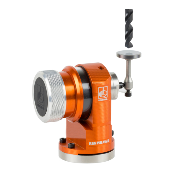
Page 26: Tool Setter Dimensions
Tool setter dimensions 44 .75 (1 .76) 48 .65 (1 .92) 56 (2 .20) + 22 (0 .87) for battery removal Cap head bolt and T nut Ø56 (2 .20) M10/M12 (Ø0 .50) MAX Stylus overtravel limits Typical bolt length 30 (1 .18) Stylus length ±X / ±Y supplied by user... -
Page 27: Interface Dimensions
Interface dimensions 84 (3 .31) 40 (1 .58) 40 (1 .58) 40 (1 .58) 16 (0 .63) Dimensions given in mm (in) www.renishaw.com/primo... -
Page 28: Part Setter Specification
Part setter specification Principal application Used for workpiece set-up and inspection . Dimensions Length 61 .25 mm (2 .41 in) Diameter 51 mm (2 .01 in) Weight without shank (includ- 350 g (12 .35 oz) ing battery and credit token) Transmission type Frequency-hopping spread spectrum (FHSS) radio . -
Page 29: Tool Setter Specification
1 .30 N to 2 .40 N, 133 gf to 245 gf (4 .68 ozf to 8 .63 ozf) depending on sense direction . Mounting The tool setter is mounted on the machine table using a cap head bolt and T nut (not supplied by Renishaw) . Environment IP rating... -
Page 30: Interface Specification
Interface specification Principal application Used to communicate signals between the part setter or tool setter and the CNC machining centre . Dimensions Height 103 mm (4 .05 in) Width 84 mm (3 .31 in) Depth 40 mm (1 .57 in) Weight (with 8 m (26.2 ft) cable) 950 g (33 .51 oz) Transmission type... -
Page 31: System Installation
The signal LED on the interface turns gradually from green to yellow as the environment causes signal degradation . When communication fails, the LED turns off . The Primo system will continue to perform 100% effectively as long as there is signal . ideal... -
Page 32: Performance Envelopes
• Do not allow coolant or swarf residue to accumulate on the equipment . • Regularly wipe clean the part setter body and the tool setter body . • Reduction in transmission range may result when operating in temperatures outside the range of +5 °C to +55 °C (+41 °F to +131 °F) . -
Page 33: Preparing The Part Setter
Preparing the part setter Fitting the stylus To obtain the most accurate results from your part setter, it is recommended that you fit a Renishaw manufactured stylus . 1.8 Nm – 2.2 Nm (1.3 lbf.ft – 1.6 lbf.ft) M-5000-3707 www.renishaw.com/primo... -
Page 34: Installing The Battery
Installing the battery NOTES: See "Maintenance" on page 6-1 for a list of suitable battery types . Ensure the product is clean and dry before inserting batteries . Do not allow coolant or debris to enter the battery compartment . When inserting batteries, check that the battery polarity is correct . -
Page 35: Mounting The Part Setter On A Shank
Mounting the part setter on a shank 2 mm A/F 0 .5 Nm – 1 .5 Nm (0 .37 lbf .ft – 1 .1 lbf .ft) (× 2) www.renishaw.com/primo... -
Page 36: Part Setter Stylus On-Centre Adjustment
Part setter stylus on-centre adjustment NOTES: If a part setter and shank assembly is dropped, it must be rechecked for correct on-centre adjustment . Do not hit the part setter to achieve on-centre adjustment . 1 .5 Nm – 2 .2 Nm (1 .1 lbf .ft –... -
Page 37: Preparing The Tool Setter For Use
(1 .84 lbf .ft – 1 .99 lbf .ft) Stylus weak link break stem 2 mm A/F 1.0 Nm – 1.2 Nm (0 .74 lbf .ft – 0 .89 lbf .ft) Captive link 3 mm 2.5 Nm – 2.7 Nm (1.84 lbf.ft – 1.99 lbf.ft) www.renishaw.com/primo... -
Page 38: Installing The Battery
Installing the battery NOTES: See "Maintenance" on page 6-1 for a list of suitable battery types . Ensure the product is clean and dry before inserting batteries . Do not allow coolant or debris to enter the battery compartment . When inserting batteries, check that the battery polarity is correct . -
Page 39: Mounting The Tool Setter On A Machine Table
Reattach the tool setter to the base . 4 mm A/F 4 .6 Nm – 5 .6 Nm (3 .39 lbf .ft – 4 .13 lbf .ft) 3 mm A/F 2 .5 Nm – 2 .7 Nm (1 .84 lbf .ft – 1 .99 lbf .ft) × 2 www.renishaw.com/primo... -
Page 40: Tool Setter Stylus Level Setting
Tool setter stylus level setting The top surface of the stylus must be set level . Front-to-back level adjustment NOTE: It is strongly recommended that you make this adjustment first. To raise the front: Slacken screw 2 and adjust the height with screw 1 until the stylus is level . To lock the position, fully tighten screw 2 . - Page 41 Alternately adjust the grub screws . This causes the tool setter to rotate and change the stylus level setting . When the stylus surface is level, tighten the grub screws . 2 .5 mm A/F 0.7 Nm – 0.9 Nm (0.52 lbf.ft – 0.66 lbf.ft) × 2 www.renishaw.com/primo 5-11...
-
Page 42: Preparing The Interface For Use
Preparing the interface for use Mounting bracket (optional) NOTE: Install the interface with the cable exiting from the lower side for good coolant run-off . 4 mm A/F 8 mm A/F (0 .98) (0 .98) 100 .50 (3 .95) 45 º 2 .0 (0 .08) 45 (1 .77) 90 (3 .54) Dimensions given in mm (in) -
Page 43: Interface Wiring Diagram
Error (SSR) Green/black White Machine start input P1 (part setter) Brown Machine start common Pink Machine start input P2 (tool setter) 12 V to 30 V Power supply (12 V to 30 V) Black Screen Green/yellow Machine ground (star point) www.renishaw.com/primo 5-13... -
Page 44: Interface Cable
Interface cable Cable specification Length 8 m (26 .25 ft) Number of cores 15 cores and screen Diameter 7 .5 mm (0 .29 in) Dimensions of each core 15 cores and screen A ferrule should be crimped onto each cable wire for a more positive connection at the terminal box . A cable sealing gland prevents coolant and dirt from entering the interface . -
Page 45: Interface Screw Torque Values
2.5 Nm – 2.7 Nm (1.84 lbf.ft – 1.99 lbf.ft) × 2 T10 tamperproof 1 Nm 4 positions 8 mm A/F 4 mm A/F 4.0 Nm – 6.0 Nm (2.95 lbf.ft – 4.43 lbf.ft) × 2 Mounting HOLD bracket 22 mm A/F 6.0 Nm – 8.0 Nm (4.43 lbf.ft – 5.90 lbf.ft) × 2 www.renishaw.com/primo 5-15... -
Page 46: Calibrating The Primo Equipment
. To ensure accurate results during use of the Primo system it is vital that the measuring feedrates used to set parts and tools are the same as the feedrates used to calibrate the part setter and the tool setter . -
Page 47: Goprobe Training Part Calibration
GoProbe which make calibration quick and easy . To find out more about GoProbe training part calibration and the GoProbe training kit visit. www.renishaw.com/goprobe . Calibrating the part setter only Three different operations are to be used when calibrating the part setter . They are: •... -
Page 48: Calibrating The Tool Setter Only
Calibrating the tool setter only The purpose of calibration is to establish the trigger point values of the measuring face of the tool setter’s stylus under normal measuring conditions . Calibration should be run at the same feedrate as probing . The calibration values are stored in macro variables for computation of the tool size during tool setting cycles . -
Page 49: Operational Mode (All Signals Repeat)
. Errors LED colour Status Graphic hint Continuous violet Contact Renishaw Continuous red Battery dead Continuous yellow Credit exhausted Credit transfer mode (part setter only) For more information, see "Credit transfer" on page 5-32 . -
Page 50: Interface Led Signals
Interface LED signals Key to LED symbols Solid Flashing Gradient REMAINING CREDIT DISPLAY PART SETTER LED TOOL SETTER LED Number displayed indicates the remaining days of credit available Part setter switched on Tool setter switched on Error codes displayed Part setter must be reacquired Tool setter switched off Part setter switched off SIGNAL LED... -
Page 51: Acquisition Mode
The part setter LED stays acquired on for 5 seconds. Tool setter The tool setter LED stays acquired on for 5 seconds. Part setter The part setter and tool and tool setter setter LEDs stay on for 5 acquired seconds . www.renishaw.com/primo 5-21... -
Page 52: Operational Mode
Operational mode The LEDs provide the following information during operational mode . Graphic display System status Details Part credit/ Probe Tool Start Error Signal setter status setter battery Standby System in standby mode . Start signal When set to level start, the start LED will stay yellow until the part setter or tool setter starts . -
Page 53: Error States
System The low credit/low battery, overcurrent status and error LEDs will flash . The error LEDs will continue to flash until the fault is cleared and the power is cycled . Hardware Contact Renishaw . validation failure www.renishaw.com/primo 5-23... -
Page 54: Error Codes
E02 = Multiple active equipment error E08 = Acquisition required (incorrect DIP switch state for switch-on method) E20 = Output overcurrent Flashing codes = Credit transfer mode = Acquisition mode All other codes should be reported to Renishaw . 5-24 Primo™ system: System installation... -
Page 55: Acquisition Method
Key to the symbols LED short flash LED medium flash LED long flash NOTE: The interface will be switched off and on again during the part setter acquisition . PROBE STATUS LED LED check PROBE STATUS LED Probe status check www.renishaw.com/primo 5-25... - Page 56 PROBE STATUS LED Switch the interface off and then back on to activate acquisition mode . Part setter entering acquisition waiting Interface trying to establish communication with part setter (may take up to 11 seconds) PROBE STATUS LED Interface has identified the Part setter has identified part setter the interface...
-
Page 57: Tool Setter
Key to the symbols LED short flash LED medium flash LED long flash NOTE: The interface will be switched off and on again during the tool setter acquisition . PROBE STATUS LED LED check PROBE STATUS LED Probe status check www.renishaw.com/primo 5-27... - Page 58 PROBE STATUS LED Switch the interface off and then back on to activate acquisition mode . Tool setter entering acquisition waiting Interface trying to establish communication with tool setter (may take up to 11 seconds) PROBE STATUS LED Interface has identified the Tool setter has identified tool setter the interface...
-
Page 59: Installing The Credit Token Cassette
Installing the credit token cassette NOTE: The part setter automatically enters credit transfer mode . For more information, see "Credit transfer" on page 5-32 . www.renishaw.com/primo 5-29... -
Page 60: Changing The Credit Token
Changing the credit token NOTE: Ensure that the credit token is installed in the part setter in the orientation shown in step 4 . Failure to do this will result in the credit not being transferred . Correct orientation 5-30 Primo™ system: System installation... - Page 61 NOTE: The part setter automatically enters credit transfer mode . For more information, see "Credit transfer" on page 5-32 . www.renishaw.com/primo 5-31...
-
Page 62: Credit Transfer
Credit transfer NOTES: Once credit transfer has been initiated, it cannot be interrupted . Once the credit has been transferred, do not remove the token from the part setter . Key to the symbols LED short flash LED medium flash PROBE STATUS LED LED long flash LED check... - Page 63 PROBE STATUS LED Credit transfer complete PROBE STATUS LED PROBE STATUS LED × Credit transfer failed Credit transfer successful PROBE STATUS LED NOTE: If credit transfer fails, the probe will revert to “Credit transfer ready” . Credit transfer ready www.renishaw.com/primo 5-33...
- Page 64 This page is intentionally left blank . 5-34 Primo™ system: System installation...
-
Page 65: Maintenance
Introduction You may undertake the maintenance routines described in these instructions; further dismantling and repair of Renishaw equipment must be carried out by an authorised Renishaw Service Centre . Cleaning the equipment Wipe the window of the part setter and the body shell of the tool setter with a clean cloth on a regular basis to remove machining residue . -
Page 66: Changing The Battery
Changing the battery Part setter See the table on page 6-4 for a list of suitable battery types . See "Safety" on page 1-3, for battery safety information . NOTES: Always ensure that the seal and mating surfaces are clean and free from dirt before reassembly . After removing the old battery, wait at least 5 seconds before inserting the new battery. -
Page 67: Tool Setter
Always ensure that the seal and mating surfaces are clean and free from dirt before reassembly . After removing the old battery, wait at least 5 seconds before inserting the new battery. If a dead battery is inadvertently inserted into the probe, the LEDs will remain a constant red or off . www.renishaw.com/primo... - Page 68 Battery types CR2 (3 V) lithium-manganese dioxide × 2 ½ AA lithium-thionyl chloride × 1 Energizer: Saft: EL1 CR2 LS 14250 C, LS 14250 Duracell: Tadiran: Ultra CR2 SL-750 Xeno: XL-050F Primo™ system: Maintenance...
-
Page 69: Interface Cover
Clean thoroughly to ensure no debris or coolant enters the unit . Unscrew (but do not remove) each captive screw and washer evenly from the cover using the T10 tamperproof key . Using the T10 tamperproof key, tighten each captive screw to 1 Nm . www.renishaw.com/primo... -
Page 70: Routine Tool Setter Maintenance
Routine tool setter maintenance Ensure the tool setter is securely mounted and keep all electrical connections clean . Inspect the diaphragm once a month . NOTE: In the event of the diaphragm seal being damaged, return the tool setter to your supplier for repair . Inspecting the diaphragm seal Remove the stylus/break stem assembly . - Page 71 Inspect the diaphragm seal for signs of If there is no damage, reassemble the tool setter . piercing or damage . www.renishaw.com/primo...
- Page 72 This page is intentionally left blank . Primo™ system: Maintenance...
-
Page 73: Fault-Finding
The workpiece is obstructing the path of Review the software and the program (refer crashes. the part setter . to the programming manual) . The part setter’s length offset is missing . Review the software and the offsets (refer to the programming manual) . www.renishaw.com/primo... - Page 74 Symptom Cause Action Poor part setter Debris on the part or the stylus . Clean the part and the part setter’s stylus . repeatability and/or accuracy. Poor tool change repeatability . Recalibrate the part setter after each tool change (refer to the programming manual) . Loose part setter mounting on the Check the part setter has been mounted shank or loose part setter stylus .
- Page 75 The part setter battery is low (a flashing Replace the battery in the part setter soon credit/low battery LED (see page 6-2 . blue LED will be shown on the part is lit red. setter; see page 5-19) . www.renishaw.com/primo...
- Page 76 Symptom Cause Action The interface low Replace the credit token (see page 5-32) There is low credit in the system and credit/low battery LED the part setter battery is low (a flashing and the battery (see page 6-2) in the part is flashing yellow/red.
- Page 77 Check the spin speed (see page 2-2 and method only) . refer to the programming manual) . Radio link failure or the part setter is Check the position of the interface and out of range . remove any obstructions (see page 5-1) . www.renishaw.com/primo...
-
Page 78: Tool Setter
Tool setter Symptom Cause Action The tool setter fails Dead battery . Change the battery (see page 6-2) . to power up (LED not illuminated). Unsuitable battery . Change the type of battery being used (see page 6-5) . The battery is inserted incorrectly . Check the battery insertion and polarity (see page 6-3) . - Page 79 (refer to the programming manual) . Temperature variation causes Minimise temperature variation (refer to machine and tool movement . the machine tool documentation) . The machine tool is faulty . Perform health checks on the machine tool (refer to the machine tool documentation) . www.renishaw.com/primo...
- Page 80 Symptom Cause Action The tool setter LED does Radio link failure or the tool setter is Check the position of the tool setter and not correspond to the out of range . the interface (see page 5-2) . interface LEDs. The tool setter has been enclosed or Remove the obstruction .
- Page 81 30 seconds and hibernation mode after a further 30 seconds if no signal is received. Radio link failure or the tool setter is out Check the position of the tool setter and the of range . interface (see page 5-2) . www.renishaw.com/primo...
-
Page 82: Interface
Interface Symptom Cause Action No LEDs lit on the No power to the interface . Check the interface wiring (see page interface. 5-13) . The interface status Radio link failure or the selected probe is Check the position of the selected probe LED does not out of the interface range . -
Page 83: Parts List
Interface with 8 m (26.2 ft) cable, tool kit and product card. A-5475-0001 LTS with 8 m (26.2 ft) cable and product card GoProbe software Contact Renishaw GoProbe software package with cycles for part setting, tool setting and calibration . GoProbe training Contact Renishaw GoProbe training kit with pocket guide, GoProbe training part, e-learning course and quick-reference tool . - Page 84 Primo system H-5470-8504 Installation guide: for set-up of the Primo system . Data sheet H-5470-8200 Data sheet: Technical information and specifications for the Primo system . Programming H-5990-8600 Programming manual: For instructions on how to use GoProbe software . manual...
- Page 85 This page is intentionally left blank . www.renishaw.com/primo...
- Page 86 © 2015–2022 Renishaw plc . All rights reserved . This document may not be copied or reproduced in whole or in part, or transferred to any other media or language by any means, without the prior written permission of Renishaw .
Need help?
Do you have a question about the Primo System and is the answer not in the manual?
Questions and answers