
Related Manuals for Renishaw PH10 Series


Summary of Contents for Renishaw PH10 Series
- Page 1 User’s guide H-1000-5070-13-A PH10 motorised head series EXTENDED WARRANTY Now available for this product. Contact your vendor. www.renishaw.com/ew...
- Page 2 EXCLUDES LIABILITY, HOWSOEVER ARISING, FOR ANY INACCURACIES IN THIS DOCUMENT. Trademarks RENISHAW® and the probe emblem used in the RENISHAW logo are registered trademarks of Renishaw plc in the UK and other countries. apply innovation is a trademark of Renishaw plc.
- Page 3 PH10 motorised probe head series user’s guide...
- Page 4 Information to user (FCC section 15.21) The user is cautioned that any changes or modifications not expressly approved by Renishaw plc or its authorised representative could void the user’s authority to operate the equipment. Special accessories (FCC section 15.27)
- Page 5 Reports demonstrating compliance have been compiled and are available on request, in paper format, to market surveillance authorities. Person authorised to compile the Renishaw technical file and issue the declaration of conformity is: Mark Acres Compliance Manager...
- Page 6 Do not rely on probe signals to stop machine movement. If the equipment is used in a manner not specified by the manufacturer, the protection provided by the equipment may be impaired. The expected method of providing an emergency stop for Renishaw products is to remove power.
- Page 7 Safety International safety instructions Предупреждения: Моля, обърнете на приложение 1 и прочетете инструкциите за безопасност на вашия собствен език, преди за разопаковате и монтирате този продукт. UPOZORNĚNÍ: Před rozbalením a instalací tohoto výrobku čtěte bezpečnostní pokyny uvedené v Příloze 1. ADVARSLER: Læs sikkerhedsinstrukserne i Appendix 1 FØR udpakning og installation af dette produkt! SICHERHEITSANWEISUNGEN: Lesen Sie die Sicherheitsanweisungen in Ihrer...
- Page 8 Safety WAARSCHUWINGEN: Ga nu naar Appendix 1 en lees de veiligheidsinstructies, in uw eigen taal, voordat u dit product uitpakt en installeert. OSTRZEŻENIA: Przed rozpakowaniem i instalacja produktu nalezy przeczytac zalacznik nr 1 i zapoznac sie z zasadami bezpieczenstwa w jezyku uzytkownika. ATENÇÃO: Você...
- Page 9 Safety Electrical requirements The PHC10-2 is powered from the a.c. mains supply via an IEC 320 connector. The operating voltages of the unit are as follows: 100 - 240 V ac +10%, -15% 47 - 66 Hz 30 W maximum Fuse replacement There are two 2 Amp (T) slow-blow fuses which are used for all voltages (one is a spare).
- Page 10 Safety Environmental requirements The following environmental conditions comply with those defined in BS EN61010 - 1:2001: Indoor use IP30 (no protection against water) Altitude Up to 2000 m Operating temperature PH10: +10 °C to +40 °C PHC10-2: 0 °C to +50 °C Storage temperature -10 °C to +70 °C Relative humidity PH10: 80 % maximum for temperatures up to +31 °C.
-
Page 11: Table Of Contents
Contents Contents 1 Introduction ......................11 2 System description ....................12 Introduction ....................12 PH10 motorised probe head range ..............12 Features .......................13 PH10T ......................13 PH10M ......................14 PH10MQ .......................15 Probe head specification ................16 PHC10-2 probe head controller ..............18 HCU1 hand control unit ................21 2.10 PH10 probe carrying capability ..............22 2.11 Connection of probes and extensions ............24... - Page 12 Contents Datum error ....................40 Obstruct error ....................41 Overload error ....................41 6 Maintenance ......................42 Maintenance ....................42 Cleaning .......................42 7 Appendix 1 - International safety statements ............43 BG - ПРЕДУПРЕЖДЕНИЯ ..................43 CS - UPOZORNĚNÍ ....................44 DA - ADVARSLER ....................45 DE - SICHERHEITSANWEISUNGEN ..............46 EL - ΠΡΟΕΙΔΟΠΟΙΉΣΕΙΣ...
-
Page 13: Introduction
This user’s guide will enable you to maximise the performance of your PH10 system and ensure, safe reliable operation. Please fill in the user registration form at the end of this guide and return it to Renishaw plc to obtain further information on the PH10 system and accessories. This will enable Renishaw to keep you informed of the latest product information, special offers, upgrade news and new product developments. -
Page 14: System Description
A list of possible operating errors is also given together with maintenance information. The installation of the PH10 system is described in the PH10 series installation guide (Renishaw part number H-1000-5071) which is intended primarily for use by the CMM supplier for installation and commissioning purposes. -
Page 15: Features
System description Features All the heads in the range incorporate the following features: • 720 indexing positions • 0.4 µm indexing repeatability * • 7.5° indexing steps in both axes • 300 mm (maximum) extension bar capability* See section 2.7 for specifications and test conditions. PH10T Figure 1 shows the PH10T motorised probe head fitted with a TP200 probe. -
Page 16: Ph10M
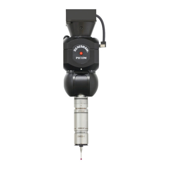
System description PH10M Figure 2 shows the PH10M motorised probe head fitted with an AM1 adjustment module and an SP25M probe. B axis A axis Figure 2 - PH10M... -
Page 17: Ph10Mq
System description PH10MQ Figure 3 shows the PH10MQ motorised probe head fitted with an AM2 adjustment module and a TP7M probe. B axis A axis Figure 3 - PH10MQ... -
Page 18: Probe Head Specification
System description Probe head specification Table 1 - Probe head specification Repeatability of <0.4 µm (0.00002 in) - equivalent to a TP20 PH10T position (2s) and stylus (part number A-5000-3604) PH10M <0.4 µm (0.00002 in) - equivalent to a TP6A and stylus (part number A-5000-3553) PH10MQ Accuracy of step... - Page 19 System description 62 mm (2.44 in) PH10T 102 mm B axis PH10M (4.0 in) 62 mm (2.44 in) 25 mm A axis (0.98 in) B axis 117 mm (4.6 in) A axis 38 mm 60 mm (1.5 in) (2.36 in) square 10 mm (0.39 in)
-
Page 20: Phc10-2 Probe Head Controller
System description PHC10-2 probe head controller The PH10 series of motorised probe heads can be used in conjunction with either the PHC10-2 controller or the UCC (universal CMM controller). The PHC10-2 incorporates an integral power supply for the head, manages all head functions and communicates via a suitable interface with the CMM computer. - Page 21 System description 2.8.2 PHC10-2 front panel Figure 5 shows the LEDs on the front panel of the PHC10-2. The names, colours and functions of the LEDs are given in table 3. Figure 5 - LEDs Table 3 - LEDs LED name Colour Description POWER ON...
- Page 22 System description 2.8.3 PHC10-2 rear panel Figure 6 shows the rear panel of the PHC10-2. Figure 6 - Rear panel Switches 1-10, communications protocol selection HCU1 connector Either RS232 communications connector or IEEE488 communications connector Version number Serial number Main power ON/OFF switch Fuse holder Mains power input PICS output connector...
-
Page 23: Hcu1 Hand Control Unit
System description HCU1 hand control unit The HCU1 hand control unit shown in figure 7 is an optional control which enables the system to be used in manual mode or in a teach cycle. A LCD dot matrix display provides information on system status. Figure 7 - HCU1... -
Page 24: Ph10 Probe Carrying Capability
System description 2.10 PH10 probe carrying capability Figure 8 shows the range of extensions, probes and styli which can be used in conjunction with the PH10T head. PH10T PEL1 PEL2 PEL3 PEL4 M2 thread styli M3 thread styli Figure 8 - Extensions, probes and styli... - Page 25 System description Figure 9 shows the range of extensions, probes and styli which can be used in conjunction with the PH10M and PH10MQ heads. Shank Quill PH10M PH10MQ PAA1 PEM25 PEM25* PEM1 PEL1 PAA2 PEM2 PEL2 PEM3 SP600M* SP25M** PEL3 PAA3 TP2-5W TP6A...
-
Page 26: Connection Of Probes And Extensions
Connection of probes and extensions 2.11.1 M8 connection The PH10T is designed to carry Renishaw probes and extensions with an M8 screw thread (see figure 10). Probes and extensions are screwed into the probe head’s bush and tightened with the appropriate spanner. -
Page 27: Probes
System description Head or extension bar Clamping mechanism Kinematic location Electrical contacts Lock/unlock screw PAA1 adaptor Figure 11 - Autojoint connection 2.12 Probes 2.12.1 M8 touch-trigger probes This range of probes (see table 4) utilises the M8 bush as a mounting for the head. These can be fitted directly onto the PH10T head, but when used with the PH10M or PH10MQ heads, one of the autojoint to M8 bush extension bars or the PAA1 adaptor must be used (see figure 8 and 9). -
Page 28: Probe Extension Bars
System description 2.12.2 Multiwired probes This range of probes (see table 5) is compatible with the PH10M and PH10MQ heads only and utilise the Renishaw multiwired autojoint connection to the head. Table 5 - Multiwire probe Probe Application Diameter Weight User’s guide... - Page 29 System description There are three types in the range: • Autojoint to M8 bush (PAA series) • Autojoint to autojoint (PEM series) • M8 thread to M8 bush (PEL series) 2.13.1 Autojoint to M8 bush These extension bars connect directly to the autojoint of the PH10M or PH10MQ head and terminate in an M8 bush (see table 6).
- Page 30 System description The S1 spanner is designed to fail before damage can occur to the mechanical joint between the two parts. Using the S1 spanner, fully hand-tighten the probe body into the M8 bush (0.3 Nm to 0.5 Nm). 2.13.2 Autojoint to autojoint These extension bars are compatible with the PH10M and PH10MQ heads.
-
Page 31: Styli
For further information on the Renishaw stylus range, please refer to the Renishaw stylus and accessories guide (Renishaw part number H-1000-3200). Renishaw also offers a custom design service if your requirements are not met by the standard range. Please contact your Renishaw supplier for details. -
Page 32: Accessories
Accessories Accessories Adjustment modules The AM1 adjustment module shown in figure 13 is designed for use on the PH10T and PH10M. Lock/unlock screw Roll Pitch Overtravel Figure 13 - AM1 adjustment module... - Page 33 The AM1 offers a quick release mechanism for rapid head exchange, and features inbuilt overtravel protection. For further information on the AM1, please refer to the AM1 user’s guide (Renishaw part number H-1000-4010). For further information on the AM2, please refer to the...
-
Page 34: Trigger Force Gauge (Gram Gauge)
For further information on the trigger force gauge, please refer to the trigger force gauge guide (Renishaw part number H-1000-4054). NOTE: To convert mass in grams to trigger force in Newtons the following equation is... -
Page 35: Machine Checking Gauge
Accessories Machine checking gauge The Renishaw machine checking gauge shown in figure 16 enables rapid and effective interim checking of CMM performance as recommended by many standards for CMM volumetric performance assessment. +45° -45° Figure 16 - Machine checking gauge Please contact your Renishaw representative to arrange a demonstration, or refer to the machine checking gauge user’s guide (Renishaw part number H-1000-5080). -
Page 36: Universal Datum Sphere
Accessories Universal datum sphere The Renishaw universal datum sphere shown in figure 17 features quick and easy alignment of its ball stem over a wide range of angles, allowing clearance for probe qualification above, centrally and below the ball. Figure 17 - Universal datum sphere Each hard-wearing tungsten carbide sphere is supplied with a test certificate traceable to UK (National Physical Laboratory) standards. - Page 37 ACR3 is a passive modular autochange rack with four ports and is driven by the motion of the CMM. Two ACR3s can be linked to provide an eight port system. The ACR3 is mounted on the horizontal Renishaw MRS (modular rail system).
-
Page 38: System Operation
System operation System operation Introduction Figure 19 shows the basic installation configuration for the PH10 system. Machine cable PHC10-2 head Communications controller connection to CMM computer Head cable connects head to PICS product machine cable interconnection cable Probe interface (PI 200) HCU1 hand control unit (optional) -
Page 39: Caution
In manual mode the optional HCU1 hand control unit is used to control head and probe functions. If the HCU1 is connected to the PHC10-2 controller when power is applied to the system, the system will enter manual mode. For further information refer to the HCU1 user’s guide (Renishaw part number H-1000-5016). 4.2.2 Automatic mode In automatic mode the system is under the control of the CMM computer. -
Page 40: Troubleshooting
Renishaw representative for further advice. The optional HCU1 is also able to diagnose certain error conditions. Please refer to the HCU1 user’s guide (Renishaw part number H-1000-5016) for further information. NOTE: Before seeking technical assistance please make a note of the following information: •... -
Page 41: Poor Measurement Performance
Possible cause Checks/remedies Probe incorrectly installed Remove probe and refit. Cable/connections faulty Check conditions and integrity of cabling from head to controller. Probe failure Contact your CMM’s supplier or Renishaw representative for further assistance. Probe output disabled by Check probe output. -
Page 42: No Head Movement
Check conditions and integrity of cabling from head to controller. Head/stylus configuration Remove obstruction and update head using the HCU1 obstructed or under CMM control. Probe extension Use shorter/lighter styli combination. combination too long Internal head fault Contact your Renishaw representative, CMM manufacturer or distributor. -
Page 43: Obstruct Error
Probe extension Use shorter/lighter styli combination. combination too long Internal head fault Contact your Renishaw representative, CMM manufacturer or distributor. Overload error The OVERLOAD ERROR and STOP LEDs are lit on the controller. The head has been overloaded while locked. -
Page 44: Maintenance
There are no user serviceable parts inside any PH10 system units. The only maintenance required is fuse replacement. See page 7 for instructions on fuse replacement. Units requiring attention must be returned to an authorised Renishaw customer service centre. Cleaning The probe head, controller and hand control unit should be cleaned with a soft, dry, lint- free cloth. -
Page 45: Appendix 1 - International Safety Statements
Препоръчва се защита на очите във всички приложения, включващи използване на машини или CMM. Обикновено в приборите Renishaw с мрежово захранване няма части, които да се обслужват от потребителя. Дефектиралите прибори да се връщат в сервизния център за обслужване на клиенти на Renishaw. -
Page 46: Cs - Upozornění
Spálené pojistky nahraďte novými pojistkami stejného typu. Pokyny naleznete v informacích o bezpečném provozu uvedených v příslušné dokumentaci k produktu. Pokyny týkající se bezpečného čištění produktů společnosti Renishaw naleznete v části věnované informacím o údržbě v příslušné dokumentaci k produktu. -
Page 47: Advarsler
I alle tilfælde, hvor der anvendes værktøjs- og koordinatmålemaskiner, anbefales det at bære beskyttelsesbriller. Der er normalt ingen dele inde i Renishaw-enhederne, som sluttes til lysnettet, der kan efterses eller repareres af brugeren. Send alle defekte enheder til Renishaws kundeservicecenter. -
Page 48: Sicherheitsanweisungen
Beachten Sie die Bedienungsanleitungen des Maschinenherstellers. Es obliegt dem Maschinenlieferanten, den Anwender über alle Gefahren, die sich aus dem Betrieb der Ausrüstung, einschließlich der, die in der Renishaw Produktdokumentation erwähnt sind, zu unterrichten und sicherzustellen, dass ausreichende Schutzvorrichtungen und Sicherheitsverriegelungen eingebaut sind. -
Page 49: El - Προειδοποιήσεισ
της κίνησης του μηχανήματος. Εάν ο εξοπλισμός χρησιμοποιείται με τρόπο μη προδιαγεγραμμένο από τον κατασκευαστή, η παρεχόμενη προστασία του εξοπλισμού πιθανώς να παρεμποδίζεται. Η αναμενόμενη μέθοδος διακοπής έκτακτης ανάγκης για τα προϊόντα Renishaw είναι η αποσύνδεσή τους από το ηλεκτρικό ρεύμα. -
Page 50: Avisos
Se recomienda usar gafas de protección en todas las aplicaciones que implican el uso de Máquinas-Herramienta y máquinas de medición de coordenadas. Dentro de las unidades Renishaw que se enchufan a la red, normalmente no existen piezas que puedan ser mantenidas por el usuario. Las unidades defectuosas deben ser devueltas a un Centro de Servicio al Cliente Renishaw. -
Page 51: Hoiatused
Enne hooldustööde teostamist eemaldage toide. Vaadake masina tarnija kasutusjuhendit. Masina tarnija vastutuseks on tagada, et kasutajat teavitatakse masina tööga kaasnevatest ohtudest, kaasa arvatud need ohud, mida on mainitud Renishaw toote dokumentides, ning samuti tagada, et masinaga oleks kaasas korrektsed kaitsepiirded ja turvalukud. -
Page 52: Varoitus
Silmäsuojainten käyttö on suositeltavaa kaikkia työstökoneita ja koordinaattimittauskoneita (CMM) käytettäessä. Sähköverkkoon kytkettävät Renishaw-tuotteet eivät tavallisesti sisällä käyttäjän huollettavissa olevia osia. Vialliset osat tulee palauttaa valtuutetulle Renishaw- asiakaspalvelukeskukselle. Korvaa palaneet sulakkeet samantyyppisillä uusilla sulakkeilla. Lue tuoteselosteen TURVALLISUUTTA (SAFETY) koskeva osa. -
Page 53: Securite
Remplacer les fusibles grillés par des composants neufs du même type. Consulter les consignes de sécurité de votre documentation. Les conseils de nettoyage en toute sécurité des produits Renishaw figurent dans les consignes de maintenance de votre documentation. Mettre la machine hors tension avant d’entreprendre toute opération de maintenance. -
Page 54: Ga - Rabhaidh
Maidir le haonaid Renishaw a fhaigheann cumhacht ón bpríomhlíne, is iondúil nach mbíonn aon chodanna laistigh díobh a d’fhéadfadh an t-úsáideoir a shocrú. Seoltar aonaid fhabhtacha ar ais chuig Ionad údaraithe Renishaw um Sheirbhís do Chustaiméirí. Déan fiúsanna séidte a athsholáthar le comhpháirteanna den chineál céanna. Tagair don fhaisnéis shábhailteachta i gcáipéisíocht ábhartha an táirge... -
Page 55: Figyelmeztetések
Szerszámgépek és koordináta-mérőgépek használata során mindig javasolt a szemvédő viselése. Normális esetben a Renishaw hálózati egységeiben nincsenek felhasználó által javítható alkatrészek. A meghibásodott egységeket juttassa el valamelyik hivatalos Renishaw Vevőszolgálati Központhoz vagy Képviselethez. A kiégett biztosítékokat ugyanolyan típusú, új alkatrésszel cserélje ki. Olvassa el a megfelelő... -
Page 56: Sicurezza
Se utilizzato in modo non conforme a quanto specificato dal produttore, il dispositivo potrebbe non fornire il livello di protezione previsto. Il metodo corretto di eseguire un arresto di emergenza per i prodotti Renishaw è l’interruzione dell’alimentazione elettrica. -
Page 57: Įspėjimai
/ ilgintuvo / zondų junginio gaubto. Dirbant visus darbus, naudojant įrenginio įrankius ar valant ir prižiūrint įrenginį, rekomenduojama užsidėti apsauginius akinius. Paprastai „Renishaw” prietaisuose, maitinamuose iš elektros tinklo, nėra detalių, kurias galėtų remontuoti pats naudotojas. Grąžinkite sugedusius prietaisus „Renishaw” klientų aptarnavimo centrui. -
Page 58: Brīdinājums
Skatiet iekārtas piegādātāja ekspluatācijas instrukcijas. Iekārtas piegādātājs atbild par to, lai lietotājs būtu iepazīstināts ar jebkuriem draudiem, kas saistīti ar tās darbību (ieskaitot tos, kas minēti Renishaw izstrādājuma dokumentācijā), un lai būtu nodrošinātas atbilstošas aizsargierīces un aizsargbloķētāji. Noteiktos apstākļos zondes signāls var nepareizi norādīt zondes stāvokli. -
Page 59: Mt Twissijiet
Tiddependix fuq is-sinjali tas-sonda sabiex twaqqaf il-moviment tal-magna. Jekk dan it-tagħmir jintuża b’mod li ma jkunx speċifikat mill-manifattur, il-protezzjoni pprovduta mit-tagħmir tista’ titnaqqas. Il-metodu mistenni ta’ li jiġi provdut waqfien ta’ emerġenza għal prodotti ta’ Renishaw huwa li jintefa’ d-dawl. -
Page 60: Waarschuwingen
Vertrouw niet op de tastersignalen om de machine tot stilstand te brengen. Gebruik van de apparatuur op een manier die de fabrikant niet voorgeschreven heeft, kan het apparaat beschadigen of de bescherming beperken. U kunt in geval van nood de Renishaw apparatuur stopzetten door de stroom uit te schakelen. -
Page 61: Ostrzeżenia
Na dostawcy maszyny współrzędnościowej spoczywa odpowiedzialność za uprzedzenie użytkownika o wszelkich zagrożeniach związanych z eksploatacją łącznie z tymi, o jakich wspomina się w dokumentacji produktu Renishaw oraz za zapewnienie stosownych osłon i blokad zabezpieczających. W określonych warunkach sygnał sondy może fałszywie wskazywać stan gotowości sondy. -
Page 62: Atenção
Não se basear em sinais de apalpador para interromper o movimento da máquina. Se o equipamento for utilizado de modo não especificado pelo fabricante, a proteção oferecida pelo equipamento poderá ser prejudicada. O método sugerido para uma parada de emergência de produtos Renishaw é desligar a alimentação de energia. -
Page 63: Atenţionări
Este responsabilitatea furnizorului să se asigure că utilizatorul a fost înştiinţat asupra oricărui pericol implicat de utilizarea echipamentului, inclusiv asupra pericolelor menţionate în documentaţia produsului Renishaw, şi de asemenea să se asigure că au fost prevăzute protecţii şi interblocări adecvate. -
Page 64: Výstrahy
Vo všetkých aplikáciách zahŕňajúcich používanie obrábacích strojov alebo súradnicových meracích prístrojov sa odporúča ochrana očí. Vo vnútri zariadení Renishaw napájaných zo siete nie sú zvyčajne žiadne súčasti, ktoré by mohol opraviť používateľ. Vadné zariadenia vráťte do autorizovaného strediska služieb zákazníckom spoločnosti Renishaw. -
Page 65: Opozorila
Držite se navodil dobavitelja stroja. Odgovornost dobavitelja stroja je, da uporabnika opozori na vse nevarnosti pri delovanju, tudi na tiste, ki so navedene v Renishaw-jevi dokumentaciji, in da zagotovi vsa potrebna varovala in varnostne zapore. Signal glave lahko v določenih pogojih lažno javlja, da je sonda spravljena, zato se pri zaustavitvi stroja ne zanašajte nanje. -
Page 66: Varningar
Ögonskydd rekommenderas för alla tillämpningar, där verktygsmaskiner eller koordinatmätmaskiner används. Det finns vanligen inga delar som användaren kan utföra underhåll på inuti Renishaws nätströmsdrivna enheter. Returnera defekta delar till ett auktoriserat Renishaw kundcenter. Byt trasiga säkringar mot nya av samma typ. Se säkerhetsavsnittet i produktdokumentationen. -
Page 67: Appendix 2 - User Registration
Appendix 2 Appendix 2 - User registration To obtain further information on your PH10 system, and to enable Renishaw to keep you informed with the latest product news, please complete the user registration form overleaf and send it to: Renishaw plc... - Page 69 PH10 series installation guide Basic command set for indexing heads programmer’s guide HCU1 user’s guide Styli and accessories technical specifications Probing systems for CMMs, technical specifications Please arrange for my nearest Renishaw representative to contact me ...
- Page 70 Renishaw plc +44 (0)1453 524524 +44 (0)1453 524901 New Mills, Wotton-under-Edge, uk@renishaw.com Gloucestershire, GL12 8JR United Kingdom www.renishaw.com For worldwide contact details, please visit our main website at www.renishaw.com/contact *H-1000-5070-13*...
Need help?
Do you have a question about the PH10 Series and is the answer not in the manual?
Questions and answers