Sign In
Upload
Download
Table of Contents
Contents
Add to my manuals
Delete from my manuals
Share
URL of this page:
HTML Link:
Bookmark this page
Add
Manual will be automatically added to "My Manuals"
Print this page
×
Bookmark added
×
Added to my manuals
Manuals
Brands
Check Point Manuals
Network Hardware
UTM-1 U-5
Getting started manual
Check Point UTM-1 U-5 Getting Started Manual
Hide thumbs
1
2
3
4
5
6
Table Of Contents
7
8
9
10
11
12
13
14
15
16
17
18
19
20
21
22
23
24
25
26
27
28
29
30
31
32
33
34
35
36
37
38
39
40
41
page
of
41
Go
/
41
Contents
Table of Contents
Bookmarks
Table of Contents
Important Information
Health and Safety Information
Table of Contents
Introduction
Welcome
UTM-1 Overview
This Document Provides
Shipping Carton Contents
Terminology
Configuring UTM-1
Installing UTM-1 in the Rack
Connecting Power Cables and Powering on
Available Software Images
Initial Configuration
Using the First Time Configuration Wizard on Gaia
Starting the Gaia First Time Configuration Wizard
Welcome
Available Releases
Authentication Details
Date and Time Setup
Device Name
Network Connection
Products
Security Management Administrator
Security Management GUI Clients
Dynamically Assigned IP
Secure Internal Communication (SIC)
Summary
Using the First Time Configuration Wizard on Secureplatform
Starting the First Time Configuration Wizard
Welcome
Appliance Date and Time Setup
Network Connections
Routing Table
Host, Domain Settings, and DNS Servers
Management Type
Summary
Installing the Smartconsole GUI Clients
First Time Login to the Security Management Server
Login Process
Authenticating and Fingerprint Comparison
Configure and Install the Security Policy
Create a New Policy Package
Define a Host
Define a Network
Create the Firewall Rules
Configuring Content Inspection
Install a Policy Package
Advanced Configuration
Connecting to the UTM-1 CLI
UTM-1 Hardware
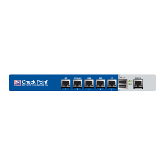
UTM-1 130 Ports
Leds on the UTM-1 130
Leds on All Other UTM-1 Models
Managing UTM-1 Using the LCD Panel
Restoring Factory Defaults
Restoring Using the Webui
Gaia
Secureplatform
Restoring Using the Console Boot Menu
Restoring Using the LCD Panel
Registration and Support
Registration
Support
Where to from here
Advertisement
Quick Links
1
Important Information
2
Utm-1 Overview
3
Configuring Utm-1
4
Connecting Power Cables and Powering on
5
Utm-1 Hardware
6
Restoring Factory Defaults
Download this manual
UTM-1
Getting Started Guide
Models: U-5, U-10, U-15,
U-20, U-30, U-40
2 July 2012
Classification: [Protected] | P/N: 704886
Table of
Contents
Previous
Page
Next
Page
1
2
3
4
5
Advertisement
Table of Contents
Need help?
Do you have a question about the UTM-1 U-5 and is the answer not in the manual?
Ask a question
Questions and answers
Related Manuals for Check Point UTM-1 U-5
Network Hardware Check Point UTM-1 Edge User Manual
Internet security appliance (707 pages)
Network Hardware Check Point UTM-1 U-10 Getting Started Manual
(41 pages)
Network Hardware Check Point UTM-1 U-15 Getting Started Manual
(41 pages)
Network Hardware Check Point UTM-1 U-20 Getting Started Manual
(41 pages)
Network Hardware Check Point UTM-1 U-30 Getting Started Manual
(41 pages)
Network Hardware Check Point UTM-1 U-40 Getting Started Manual
(41 pages)
Network Hardware Check Point 6000 Series Getting Started Manual
(49 pages)
Network Hardware Check Point 1500 Series User Manual
Universal rack mount (20 pages)
Network Hardware Check Point 1500 Series Administration Manual
(177 pages)
Network Hardware Check Point 700 Administration Manual
(206 pages)
Network Hardware Check Point QUANTUM SPARK 1500 Administration Manual
(311 pages)
Network Hardware Check Point 5000 Series Getting Started Manual
(55 pages)
Network Hardware Check Point HARMONY R81 Administration Manual
Endpoint server (451 pages)
Network Hardware Check Point QUANTUM MAESTRO Manual
(188 pages)
Network Hardware Check Point L-71 Administration Manual
1400 appliances centrally managed r77.20.85 (124 pages)
Network Hardware Check Point 6000 Series Manual
(26 pages)
This manual is also suitable for:
Utm-1 u-10
Utm-1 u-15
Utm-1 u-20
Utm-1 u-30
Utm-1 u-40
Table of Contents
Print
Rename the bookmark
Delete bookmark?
Delete from my manuals?
Login
Sign In
OR
Sign in with Facebook
Sign in with Google
Upload manual
Upload from disk
Upload from URL


Need help?
Do you have a question about the UTM-1 U-5 and is the answer not in the manual?
Questions and answers