
Related Manuals for SST Automation SSTCOMM GT100-MQ-RS


Summary of Contents for SST Automation SSTCOMM GT100-MQ-RS
- Page 1 Modbus / MQTT Gateway GT100-MQ-RS User Manual V 1.0 SST Automation E-mail: support@sstautomation.com www.SSTAutomation.com...
- Page 2 Important Information Warning The data and examples in this manual cannot be copied without authorization. SST Automation reserves the right to upgrade the product without notifying users. The product has many applications. The users must make sure that all operations and results are in accordance with the safety of relevant fields, and the safety includes laws, rules, codes and standards.
-
Page 3: Table Of Contents
Catalog 1 Product Overview ..............................1 1.1 Product Function ............................1 1.2 Product Features ............................. 2 1.3 Technical Specifications ..........................2 1.4 Related Products .............................3 1.5 Revision History .............................4 2 Hardware Description ..............................5 2.1 Product Appearance ............................5 2.2 LED Indicators ............................... 6 2.3 Configuration Button ............................6 2.4 Interfaces ................................ - Page 4 6 Working Principle ..............................41 6.1 Connection Process ............................41 6.2 Data Exchange ..............................41 Appendix A: MQTT Message Format ........................42 A.1 Default Format .............................42 A.1.1 Publish Message ..........................42 A.1.2 Subscribe Message ........................... 46 A.2 Custom Message Format ..........................49 www.SSTAutomation.com...
-
Page 5: Product Overview
1 Product Overview 1.1 Product Function GT100-MQ-RS is a gateway that can exchange data between Modbus Serial (RTU/ASCII) through RS-485 and a MQTT Broker through a wired WAN connection. It can connect Modbus RTU/ASCII Master or Slave devices to the IoT Cloud by MQTT. The wired Ethernet interface supports MQTT connections to various IoT cloud platforms such as Microsoft Azure IoT, Amazon AWS IoT, Mosquitto and other generic MQTT Brokers. -
Page 6: Product Features
1.2 Product Features One RS-485 Interface - Modbus Master/Slave As a Modbus Master interface, it can connect field devices to the IoT Cloud Platform by implementing a data acquisition and device control Ethernet network. As a Modbus Slave interface, it can integrate a PLC, DCS and other Modbus master stations into an IoT ... -
Page 7: Related Products
[6] Dimensions (W*H*D): 1.0 in * 4.0 in * 3.6 in (25 mm * 100 mm * 90 mm). [7] Installation: 1.4 in (35 mm) DIN RAIL. [8] Protection level: IP20. 1.4 Related Products Related products include: IOT600-TWX-TS GT200-MQ-IE GT200-MQ-IE To get more information about related products, please visit SST Automation’s website: www.sstautomation.com. www.SSTAutomation.com... -
Page 8: Revision History
1.5 Revision History Revision Date Chapter Description V1.0 2/16/2023 New release www.SSTAutomation.com... -
Page 9: Hardware Description
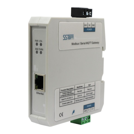
2 Hardware Description 2.1 Product Appearance Power Interface LED Indicators Ethernet Interface Serial Interface Configuration Button Note: This picture is for reference only. The product appearance is subject to the actual product. www.SSTAutomation.com... -
Page 10: Led Indicators
2.2 LED Indicators State State description The device is not powered on. Green ON The device is powered on. Green ON MQTT connection succeeded. Green Blinking MQTT connection failed. Red Blinking / OFF The RS-485 interface is sending / not sending data. TX/RX Green Blinking / OFF The RS-485 interface is receiving / not receiving data. -
Page 11: Interfaces
2.4 Interfaces 2.4.1 Power Interface The GT100-MQ-RS gateway uses a 24V DC power supply. Function GND, Power ground NC, Not connected 24V+ 24V+, DC 2.4.2 RS-485 Serial Interface The GT100-MQ-RS has an RS-485 serial interface which uses a 3-pin terminal. Its pinout is defined as follows: Function D-, RS-485 Data Negative D+, RS-485 Data Positive... - Page 12 RS-485 Installation: All stations are connected with RS-485 bus. Up to 31 stations can be connected per section. Connect a terminal resistor (120Ω, 1/2W) in parallel at both ends of the communication lines to ensure stable communication. RS-485- RS-485+ RS-485 Device 1 120Ω...
-
Page 13: Ethernet Interface
2.4.3 Ethernet Interface The Ethernet interface uses an RJ-45 connector and follows the IEEE 802.3u 100BASE-T standard. Its pinout (standard Ethernet signal) is defined below: Signal description TXD+, Transmit Data+, Output TXD-, Transmit Data-, Output RXD+, Receive Data+, Input RXD-, Receive Data-, Input www.SSTAutomation.com... -
Page 14: Mounting
3 Mounting 3.1 Mechanical Dimensions Size (width * height * depth): 1.0 in * 4.0 in * 3.6 in (25 mm * 100 mm * 90 mm) www.SSTAutomation.com... -
Page 15: Installation Method
3.2 Installation Method Using 1.4 in (35mm) DIN RAIL. Install Uninstall www.SSTAutomation.com... -
Page 16: Quick Start Guide
4 Quick Start Guide 4.1 Hardware Connection Connect the power supply to the GT100-MQ-RS as follows. Note: Please do not power on the devices before finishing and confirming all the connections. 24V+ 24V+ 24V DC Power GT100-MQ-IE Power Interface Connect the serial devices to the GT100-MQ-RS. For more details on wiring, see Chapter 2.4.2. -
Page 17: Software Configuration
4.2 Software Configuration Download, install, and run the configuration software SST-MQT-CFG. For more details, please see Chapter Download the configuration software SST-MQT-CFG from www.sstautomation.com and install it. Open the software and select the GT100-MQ-RS product. Configure the Client (MQTT Client configuration). www.SSTAutomation.com... - Page 18 Add or edit MQTT Topics. Configure the Ethernet and Subnet Interface parameters. www.SSTAutomation.com...
- Page 19 Configure the properties. Check the mapping buffer and the property names. Use the “Auto Mapping” and “Name Properties in Order” functions. Save the configuration and download to GT100-MQ-RS through network cable configuration. Note: Make sure that the GT100-MQ-RS and your computer are in the same network segment. If you can’t discover any gateways, please test the network connection first.
-
Page 20: Software Instructions
5 Software Instructions SST-MQT-CFG is the configuration software which can be used to configure GT100-MQ-RS. It can be downloaded from the product page or Download page (www.sstautomation.com/Download1/) of the website. The software is based on Windows OS. Operating System: Win7, Win10, Win11. 5.1 Software Interface Description Double click on the SST-MQT-CFG icon to enter Device Select interface. - Page 21 Select “GT100-MQ-RS” to enter the corresponding configuration interface: Title Bar Menu Bar Tool Bar Right Bar Configuration Section Device Section Comment Section www.SSTAutomation.com...
- Page 22 Toolbar: The function from left to right is: New, Save, Open, Add Node, Delete Node, AddCommand, Delete Command, Upload, Download, AutoMap, Conflict Detection, Export XLS, and Debug. New: Create a new configuration project. Save: Save the current configuration. Open: Open a configuration project. Add Node: Add a Modbus node.
-
Page 23: Mqtt
5.2 MQTT 5.2.1 Client Select the “Client” in the left tree view and enter the MQTT Client configuration window. Type of MQTT Server: Supports Generic MQTT. MQTT Broker Username: The username is used for authentication on the MQTT broker. Please refer to the corresponding MQTT server guide. - Page 24 MQTT Broker Port: The access port of the MQTT broker. Please refer to the guide of corresponding MQTT Server. Message Type: Register and Property type are the 2 options. Register: The data is directly transmitted in the following message format: "version": "1.1.1.0", "type":...
-
Page 25: Advanced Config
Remote Update Server Address: The default remote update service IP Address is 54.222.133.11. The gateway can be updated remotely by SST Automation. Please do not change this IP address. Remote Update Server Port: The default remote update server port is 8885. The gateway can be updated remotely by SST Automation. - Page 26 Edit Message Format: For example: "timestamp": |TIMESTAMP|, "values": { |#each VALUES| "name": "|PROPERTIESNAME|","v": |VALUE||#unless @last|,|/unless| |/each| |PROPERTIESNAME| is the property name, |VALUE| is the value of the tag, and |TIMESTAMP| is the time to read the tag. Please see Appendix A.2 for more details.
-
Page 27: Topic
5.2.3 Topic Right click “Topic” to add a MQTT topic. If you want to delete a topic, please right-click the topic and click “Delete Topic”. After adding a Topic, select the Topic in the left tree view to enter Topic configuration window: Note: For the setting description of Property, please refer to Chapter 5.6. -
Page 28: Ethernet
5.3 Ethernet Select Protocol: Ethernet. Assign IP Mode: Supports Manually Assign / DHCP. In DHCP mode, the gateway needs to connect to a DHCP server or switch to get a valid IP address. IP Address: IP Address of the GT100-MQ-RS. The device can be searched when the IP address is in the same network segment with the computer. -
Page 29: Subnet
5.4 Subnet Select the “Subnet” in the left tree view to enter Modbus interface configuration window. Select Protocol: The current protocol. Baud Rate: Baud Rate of the serial interface. Supports 1200, 2400, 4800, 9600, 19200, 38400, 57600, 115200. Data Bits: The number of data bits of each byte. Parity Check: Supports Odd, Even, None, Mark and Space. - Page 30 Output Cycle: The cycle time to send write command. Range: 200~2500ms. Invalid for “Modbus Slave” protocol. Scan Rate: The ratio of fast-scan command to slow-scan command. If the value is set to 10, a slow-scan command will be sent once every ten fast-scan commands are sent. Invalid for “Modbus Slave” protocol. Communication Status: Unused.
-
Page 31: Modbus Master Interface Configuration
5.4.1 Modbus Master Interface Configuration 1. Node The Configuration view supports three types of operation: Edit Menu, Edit Toolbar and Right click edit Menu. (1) Add node: Select the “Subnet” and add a new node. A new node named “Node-X” will be added under the Subnet. - Page 32 2. Modbus Command The Configuration view supports three types of operation: Edit Menu, Edit Toolbar and Right click edit Menu. (1) Add command: Select a node and add a command. The maximum command number is 100. (2) Delete command: Select a command and then delete it. It supports the commands: 01, 02, 03, 04, 05, 06, 15 and 16.
- Page 33 Note: This address refers to the protocol address. When the user enters the PLC address, there will be a pop-up window asking for confirmation. Click “OK” to convert the input address into a protocol address. Click “Cancel” to refuse the converting. Examples of PLC addresses and corresponding protocol addresses.
-
Page 34: Modbus Slave Interface Configuration
5.4.2 Modbus Slave Interface Configuration Select a Status/Register block to enter Modbus slave block configuration window. Coil/Input Status Starting Address: The start address of 0/1XXXX area. The range is 0~65535, the default is 0. Coil/Input Status Block Size: The block size of the 0/1XXXX area. The range is 0~512, and the default is 0. Holding/Input Register Starting Address: The start address of the 4/3XXXX area. -
Page 35: Tools
5.5 Tools The “Tool” option on the menu bar contains the following functions: Upload Config Download Config Confilict Detection Export Excel Communication Debug AutoMap Name Properties in Oder Properties Name Conflict Detection Remote Update Server File ... -
Page 36: Upload Config And Download Config
5.5.1 Upload Config and Download Config 1. Search Device Click “Upload” or “Download” to open the search window. It will automatically search the available devices once after opening the search window. Login: Select the device and click “Login” to upload / download the configuration. Position: Select the device and click “Position”, the ENS indicator on the selected gateway will turn red. - Page 37 2. Upload Select “Upload” to upload the gateway configuration information from the device to the software. When uploading the configuration from the gateway to the software, the pop-up window will be shown as below: www.SSTAutomation.com...
- Page 38 3. Download Select “Download” to download the configured gateway information to the gateway device. When downloading the configuration to the gateway, the pop-up window will be shown as below: Click “Cancel” and the pop-up window will ask for remote restart. The new configuration is effective after restarting.
-
Page 39: Confilict Detection
5.5.2 Confilict Detection To detect whether there are address conflicts in the mapping buffer. The configuration cannot be downloaded to the gateway if there are conflicts. This function is used for Modbus commands. The mapping buffer is divided into input area and output area. Input area address is from 0x0000 to 0x3FFF. -
Page 40: Export Excel
5.5.3 Export Excel Excel documents help users examine the configuration. Save the configuration as excel document and choose the right path. 5.5.4 Communication Debug The Communication Debug function is to Debug modbus communication and view MQTT connection information. Select “Tool” >> “Communication Debug” to open the debug window. www.SSTAutomation.com... - Page 41 Modbus RTU: When the gateway is in modbus master mode, modbus communication debug can be available. Input data: Shows serial data received from the RS-485 interface. Pause: Pause input buffer data display. Diagnose: Display specific Modbus command response status. Output data: Shows serial data transmitted from the RS-485 interface. Pause: Pause output buffer data display.
-
Page 42: Automap
MQTT: Display MQTT network connection information 5.5.5 AutoMap Click “AutoMap” to automatically calculate the non-conflicting mapped memory address for each command. www.SSTAutomation.com... -
Page 43: Property Operations
5.6 Property Operations 5.6.1 Property Configuration Click “Property” in the right bar to enter the property window. Topic Name: Select the topic for properties. Data Type: For command 1, 2, 5 and 15: The data type can be BOOL. For command 3, 4, 6 and 16: When using 1 register, the data type can be UINT/INT16. -
Page 44: Name Properties In Order
Paste Property Name: Click the right mouse button on any command option, then select paste property name selection, fill in the prompt box to paste attribute name start number and end number to complete the paste attribute name. Copy scope = Paste scope. Copy scope >... -
Page 45: Working Principle
6 Working Principle 6.1 Connection Process 6.2 Data Exchange The GT100-MQ-RS is able to connect Modbus RTU/ASCII devices to MQTT Servers, such as Amazon AWS IoT, EMQ and custom Servers. www.SSTAutomation.com... -
Page 46: Appendix A: Mqtt Message Format
Appendix A: MQTT Message Format A.1 Default Format A.1.1 Publish Message Note: "//" indicates the comments part. Property type: Read Coil Status / Input Status: "version": "1.1.1.0", //Version information "time": "19/03/07,17:04:07", //Time stamp "properties":{ //When publishing messages in property type, the GT100-MQ-RS can publish 8 properties at most in one message. - Page 47 Register / Data only type: Modbus Master: Read Coil Status/Read Input Status: Example (Read Coil Status): "version": "1.1.1.0", "type": "MODBUS_MASTER", "slave id": //The slave address of the field device "fc": 1, //Modbus function code "addr ": 0, //Modbus coil/register starting address, starting form 0 "npoint": 2, //The number in data "data":...
- Page 48 Modbus Slave : Coil Status: When only one coil' status changes: "version": "1.1.1.0", "type": "MODBUS_SLAVE", "block": 0, //Modbus Block. For example, "0" indicates the Coil Status block. "addr ": 2, //Modbus status/register starting address, starting form 0 "npoint": 1, "data": "FF", //00 or FF indicates 0 or 1.
- Page 49 Holding Register: Example: "version": "1.1.1.0", "type": "MODBUS_SLAVE", "block": 4, "addr ": 1, "npoint": 4, "data": "11,22,33,44", "time": "19/02/27,16:48:39" www.SSTAutomation.com...
-
Page 50: Subscribe Message
A.1.2 Subscribe Message Note: "//" indicates the comments part. Property type: (Up to 8 properties can be changed at one time) Modbus Master/Slave / Modbus TCP Server: Change Coil/Input Status: "properties": { "BO3": false, "BO4": true, "BO5": false Change Holding/Input Register: "properties": { "AO3": 123.5, "AO4": 321.5,... - Page 51 Force Multiple Coils: "type": "MODBUS_MASTER", "slave id": "fc": 15, //Modbus function code " addr ": 0, "npoint": 2, //The data contains multiple coils' status. "data": "ff,aa" Preset Single Register: "type": "MODBUS_MASTER", "slave id": "fc": 6, " addr ": 0, "npoint": 2, "data": "aa,bb"...
- Page 52 Modbus Slave: Change single input status bit: "type": "MODBUS_SLAVE", "block": 1, //Modbus Block. "1" indicates the Input Status block. "addr ": 0, "npoint": 1, "data": "FF" Change multiple input status bits: "type": "MODBUS_SLAVE", "block": 1, "addr": "npoint": 8, //In this example, 8 bits are sent in a byte. "data": "aa"...
-
Page 53: Custom Message Format
A.2 Custom Message Format "timestamp": |TIMESTAMP|, "values": { |#each VALUES| "name": "|PROPERTIESNAME|", "v": |VALUE||#unless @last|,|/unless| |/each| (1) Variable description |PROPERTIESNAME|: Property Name. For example, AI1. |VALUE|: The value of the property. |TIMESTAMP|: The time when the property was read. (2) Grammar |#each VALUES| |PROPERTIESNAME|, |VALUE|, |TIMESTAMP|, |/each|... - Page 54 Message example: "AI1_value": 23, "AI1_timestamp": 1456150184825, "AI2_value": 17, "AI2_timestamp": 1456150184984, … (3) Additional grammar description: |#unless @last|,|/unless| This line means "Must insert a comma at the end of each line, unless it's the last line". It cancels the comma in the last line.
Need help?
Do you have a question about the SSTCOMM GT100-MQ-RS and is the answer not in the manual?
Questions and answers