
Related Manuals for SST Automation GT100-CO-RS


Summary of Contents for SST Automation GT100-CO-RS
- Page 1 Modbus / CANopen Gateway GT100-CO-RS User Manual V 2.2 Rev A SST Automation E-mail: SUPPORT@SSTCOMM.COM WWW.SSTCOMM.COM...
- Page 2 The product has many applications. The users must make sure that all operations and results are in accordance with the safety of relevant fields, and the safety includes laws, rules, codes and standards. Copyright Copyright © 2022 by SST Automation. All rights reserved. Trademark is the registered trade mark of SST Automation.
-
Page 3: Table Of Contents
GT100-CO-RS Modbus CANopen Gateway User Manual Catalog 1 Product Overview..............................1 1.1 Product Function.............................1 1.2 Product Feature............................... 1 1.2.1 CANopen Master/Modbus Slave......................1 1.2.2 CANopen Slave/Modbus Master......................1 1.3 Technical Specifications..........................2 1.3.1 CANopen Master/Modbus Slave......................2 1.3.2 CANopen Slave/Modbus Master......................3 1.4 Related Products............................. 4 1.5 Revision History............................. -
Page 4: Product Overview
User Manual 1 Product Overview 1.1 Product Function GT100-CO-RS can act as two different communication gateways, that is: (1) A communication gateway between CANopen master protocol and Modbus slave protocol, can establish connection between one CANopen slave and Modbus master device. -
Page 5: Technical Specifications
GT100-CO-RS Modbus CANopen Gateway User Manual transmission and Timestamp. Supports maximum 8 bytes TPDO and RPDO, 4 bytes fast Download SDO and fast Upload SDO. Supports up to 64 TPDO, 64 RPDO and SDO visit for input/output data exchange buffer. -
Page 6: Canopen Slave/Modbus Master
GT100-CO-RS Modbus CANopen Gateway User Manual Data bits: 8. Parity: None, Odd and Even optional. Stop bits: 1 and 2 optional. [4] Power: 24VDC (11~30VDC), maximum 60mA (24VDC). [5] Operating temperature: -4℉~140℉(-20℃ to 60℃). Humidity: 5% to 95% (non-condensing). -
Page 7: Related Products
GT100-CO-RS Modbus CANopen Gateway User Manual [5] Operating temperature: -40℉~140℉(-40℃ to 60℃). Humidity: 5%~95% (non-condensing). [6] Dimensions (W*H*D):1.0 in * 4.0 in *3.6 in (25 mm * 100 mm * 90 mm). [7] Installation: 1.4 in (35 mm) DIN RAIL. -
Page 8: Hardware Descriptions
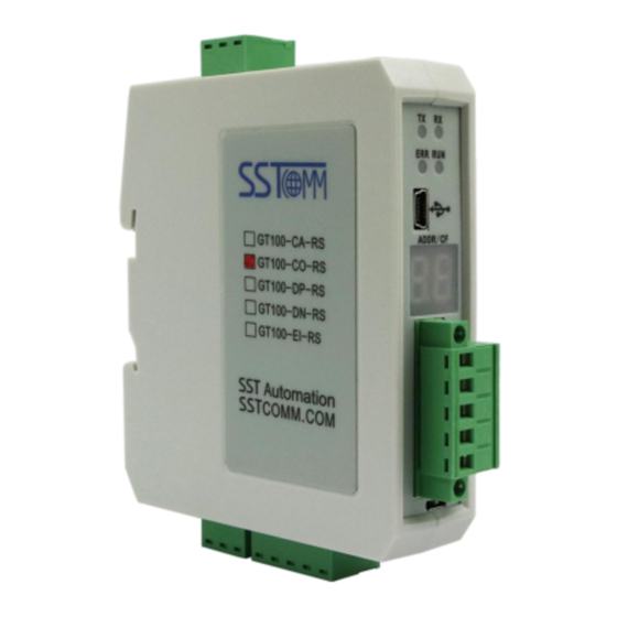
GT100-CO-RS Modbus CANopen Gateway User Manual 2 Hardware Descriptions 2.1 Product Appearance Configuration Button Power Interface Serial Status Indicator CANopen Status Indicator USB Config Port LED Display CANopen Interface RS232 Interface Terminal Resistor Switch RS485/422 Interface Notes: This picture is for reference only. The product appearance is subject to the actual product. -
Page 9: Indicators
2.3 LED Display LED Display Description The slave address when the GT100-CO-RS acts as a CANopen slave or a Modbus “01”~“99” slave. The GT100-CO-RS is in the configuration state. CAN sending error. -
Page 10: Interface
User Manual 2.5 Interface 2.5.1 Power Interface Function Power GND NC(Not Connected) 24V+, DC Positive 24V 2.5.2 CAN Interface CAN interface of GT100-CO-RS uses 5-pin connector: Wiring Pin 1 V+, 24VDC(optional) Pin 2 CAN-H Pin 3 Shield (optional) Pin 4... -
Page 11: Mini B Type Usb
GT100-CO-RS Modbus CANopen Gateway User Manual RS485/RS422 interface: Symbol RS485 Function RS422 Function Connect D+ of Connect D+ of user user device device Connect D- of Connect D- of user user device device Connect Connect shielding shielding ground ground (optional) -
Page 12: Installation
GT100-CO-RS Modbus CANopen Gateway User Manual 3 Installation 3.1 Machine Dimensions Size (width * height * depth): 1.0 in * 4.0 in * 3.6 in (25 mm * 100 mm * 90 mm) 3.2 Installation Method Using 1.4 in (35mm) DIN RAIL. -
Page 13: Quick Start Guide
Gateway User Manual 4 Quick Start Guide The following steps will help users to quickly configure GT100-CO-RS: Wiring and button setting:See also Chapter2 (1) Connect the gateway power supply and power on. Please note that two terminals of this product can be connected to the power supply, and the user only needs to connect one terminal. - Page 14 GT100-CO-RS Modbus CANopen Gateway User Manual Please confirm that the gateway is in configuration mode. The gateway is configured with USB port. Please try to connect again replacing another USB cable. Please make sure that the COM port used by the computer is correct. Try to connect again using other ...
-
Page 15: Software Instructions
Double-click the icon of the software, and you can see the "Select Device" interface of the software: Select "GT100-CO-RS", and you will see the "Select Master" interface. Select the mode you want, such as "CANopen Master/Modbus Slave", and you can see the main interface of the software: WWW.SSTCOMM.COM... - Page 16 GT100-CO-RS Modbus CANopen Gateway User Manual Title Bar Menu Bar Toolbar Configuration plate: Input configuration parameters, gray parts cannot be modified. Equipment plate: Users can select operation objects including Modbus network and Comment plate: CANopen Network and adding Explain the function of the...
-
Page 17: Working Principle
The data in Modbus output buffer of GT100-CO-RS is the data being mapped to RPDO or Download SDO commands of CANopen slave. Output mode of GT100-CO-RS is change of value, that is, until the Modbus output... - Page 18 When the “Control&Status” bit is “Enable” in configuration software (SST-CM-CFG), there are two bytes in the end of input and output buffer of GT100-CO-RS showing status of CANopen slaves and controlling status of CANopen slave. Modbus master can get the state (Operation, Preoperation, Stop state) of CANopen through GT100-CO-RS.
- Page 19 GT100-CO-RS Modbus CANopen Gateway User Manual GT100-CO-RS Heartbeat or lifeguard CANopen slave input buffer (254 Function 04 bytes) NMT Command Function 06/16 CANopen slave control command output buffer (254bytes) As is shown above, the gateway assigns 2-byte status input buffer and 2-byte control command output buffer can have up to 127 nodes in CANopen, so the aggregates is 254 bytes) for each CANopen slave respectively.
-
Page 20: Canopen Slave/Modbus Master
GT100-CO-RS Modbus CANopen Gateway User Manual …… …… …… …… …… …… …… …… …… …… 378-379 node state control command 380-381 node state control command 382-383 node state control command 6.2 CANopen Slave/Modbus Master Communication mode between CANopen and Modbus is asynchronous mode, as shown below: “Data 1”... - Page 21 GT100-CO-RS Modbus CANopen Gateway User Manual The data exchange mode between Modbus and CANopen is shown as below: The data exchange buffer size between Modbus adn CANopen is 1KB, among it input buffer is 512 bytes (Modbus slave sent, gateway received), output buffer is 512 bytes (CANopen master sent, gateway received).
- Page 22 GT100-CO-RS Modbus CANopen Gateway User Manual 0x237e Input No.510 byte of 512 bytes (1 bytes, readable) 0x237f Input No.511 byte of 512 bytes (1 bytes, readable) Index Sub-index Description 0x3000 Output No.0~No.3 byte of 512 bytes (4 bytes, writable) 0x3001 Output No.4~No.7 byte of 512 bytes (4 bytes, writable)
- Page 23 GT100-CO-RS Modbus CANopen Gateway User Manual COBID=0x600+nodeID 8 bytes data 23 mm mm nn dd dd dd dd Among them, 23 is fast read command, mm mm is index, nn is sub index, dd dd dd dd is the data needs to be written to input buffer.
-
Page 24: Typical Application
GT100-CO-RS Modbus CANopen Gateway User Manual 7 Typical Application 7.1 CANopen Master/Modbus Salve WWW.SSTCOMM.COM... -
Page 25: Canopen Slave/Modbus Master
GT100-CO-RS Modbus CANopen Gateway User Manual 7.2 CANopen Slave/Modbus Master WWW.SSTCOMM.COM... -
Page 26: Troubleshooting
Modbus slave address on Modbus network is not the same Serial indicators (TX) green blinking. with that of GT100-CO-RS ready to read. Modbus slave device on Modbus network does not support Serial indicators (TX) green blinking. the function code configured in GT100-CO-RS.
Need help?
Do you have a question about the GT100-CO-RS and is the answer not in the manual?
Questions and answers