
Related Manuals for SST Automation GT100-PN-DM


Summary of Contents for SST Automation GT100-PN-DM
- Page 1 DeviceNet/PROFINET IO Gateway GT100-PN-DM User Manual V2.0 Rev C SST Automation Email: support@sstautomation.com www.sstautomation.com...
- Page 2 The product has many applications. The users must make sure that all operations and results are in accordance with the safety of relevant fields, and the safety includes laws, rules, codes and standards. Copyright Copyright © 2022 by SST Automation. All rights reserved. Trademark is the registered trade mark of SST Automation.
-
Page 3: Table Of Contents
Catalog 1 Product Overview ................................1 1.1 Product Function ..............................1 1.2 Product Features ..............................2 1.3 Technical Specifications ............................2 1.4 Related Products ..............................3 1.5 Revision History ..............................4 2 Hardware Descriptions ..............................5 2.1 Product Appearance .............................. 5 2.2 Indicators ................................ -
Page 4: Product Overview
1 Product Overview 1.1 Product Function The product supports devices with a DeviceNet interface to connect to a PROFINET network. This module is a device on the PROFINET side and a scanner or adapter on the DeviceNet side. Application examples: [1] PROFINET device to DeviceNet scanner application Under the DeviceNet scanner mode, data exchange can be achieved between welder that supports the DeviceNet adapter protocol and Siemens PLC that supports the PROFINET master protocol. -
Page 5: Product Features
1.2 Product Features Wide application: Support as a DeviceNet scanner to connect a DeviceNet device to the PROFINET network or itself as a DeviceNet and PROFINET device to the two ends of the network. Such as: Robots with DeviceNet interfaces, inverters, motor starting protection devices, intelligent high and low voltage appliances, intelligent field measurement equipment and PLCs, etc., the PROFINET end is connected to PLCs such as Siemens S7-300 / 400/ 1200/ 1500. -
Page 6: Related Products
Support reading and writing DeviceNet adapter parameters. Support reading and writing DeviceNet I/O data(polling). Support reading cos commands (COS) (up to 14 bytes). Single DeviceNet adapter maximum support input: 128 bytes. Output: 112 bytes. Support connecting only one DeviceNet adapter, and GT200-PN-DM supports connecting multiple adapter ... -
Page 7: Revision History
1.5 Revision History Revision Date Chapter Description V1.2, Rev A 08/13/2018 V1.2_Rev A new release, Added “only one DeviceNet adapter station” to product functions. Added application examples, modified main version to product version. V1.4, Rev A 02/20/2019 Chapter 3 Remove the three-pin power interface, and change the color of the gateway to cyan. -
Page 8: Hardware Descriptions
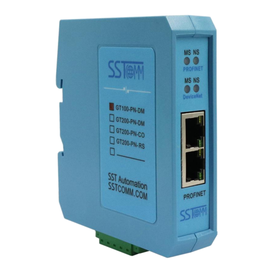
2 Hardware Descriptions 2.1 Product Appearance DIP Switch PROFINET Indicators DeviceNet Indicators PROFINET Interface DeviceNet and Power Interface Notes: This picture is for reference only. The product appearance is subject to the actual product. WWW. SSTAUTOMATION. COM... -
Page 9: Indicators
2.2 Indicators 1. PROFINET LED Indicators Description Always Red Module is running and initialization has not yet completed. Always Green Red blinking Initialization completed, no connection with PLC. Or in the normal communication with PLC, the network line is pulled out or dropped off. -
Page 10: Dip Switch
Mode(bit 1) Function(bit 2) Description Operation mode(Support SST-TD-CFG configuration) Pre-operation mode(Support SST-TD-CFG configuration) 2.4 Interface 2.4.1 Power and DeviceNet Interface GT100-PN-DM supplies power through DeviceNet port, DeviceNet and power terminal, as shown below: Wiring GND(Power GND) CAN_L SHIELD CAN_H V+(24VDC+) -
Page 11: Ethernet Interface
2.4.2 Ethernet Interface The Ethernet interface uses RJ45 interface, follows the IEEE802.3u 100BASE-T standard, 10/100M adaptive,. its pin (standard Ethernet signal) is defined as below: Signal Description TXD+, Transmit Data+ TXD-, Transmit Data- RXD+, Receive Data+ Bi-directional Data+ Bi-directional Data- RXD-, Receive Data- Bi-directional Data+ Bi-directional Data-... -
Page 12: Hardware Installation
3 Hardware Installation 3.1 Mechanical Dimensions Size (width * height * depth): 1.0 in * 4.0 in * 3.6 in (25 mm * 100 mm * 90 mm) 3.2 Installation Method Using 1.4 in (35mm) DIN RAIL. WWW. SSTAUTOMATION. COM... -
Page 13: Quick Start Guide
SST-DNET-COM is a software based on Windows platform. SST-TD-CFG is embedded in SST-DNET-COM software. It is used to configure the PROFINET and DeviceNet parameters of GT100-PN-DM. The gateway supports two modes: Pre-operation mode and Operation mode. Using DIP switch to select mode, please refer to Chapter 2.3 DIP... - Page 14 If you want to modify the PROFINET device name and IP address. Click “Tool” in the toolbar->“Assign Ethernet Parameters”. Click “Browse” in the pop-up box to select the device and click “Sign In”. As shown in the figure below, you can modify the IP address and device name at this time, click “OK” to complete the modification.
- Page 15 When the gateway serves as the DeviceNet scanner, it connects to the DeviceNet adapter device. You need to know the I/O data length of the adapter device, and then configure GT100-PN-DM in SST-TD-CFG. The user can provide this information directly, or scan the adapter device through SST-DNET-COM software to obtain this information.
-
Page 16: Sst-Td-Cfg Software Instructions
5 SST-TD-CFG Software Instructions 5.1 Software Interface Description SST-TD-CFG is embedded in SST-DNET-COM software. It is used to configure the PROFINET and DeviceNet parameters of GT100-PN-DM. Please open the SST-DNET-COM software and click the icon “ ”on the toolbar.The following figure pops up: Click “OK”... - Page 17 Notes: All the gray part in the software can not be changed. Tool bar interface is shown as below: The functions from left to right are: New, Open, Save, Add Node, Delete Node, Increase Mapping, Delete Mapping, Upload Configuration, Download Configuration, Automatic calculation of Mapping Address, Document Output, and Monitor.
-
Page 18: Device View
Subnet Mask: Set the subnet mask. Gateway Address: Set the gateway address of the LAN where GT100-PN-DM is located. Number of Input Bytes: Display the length of input data exchanged between GT100-PN-DM and PLC, the length is configured by the PROFINET project dialog. - Page 19 PROFINET configuration dialog box is shown as below: It can be seen that the above configuration has a total of three slots, respectively: 16 byte of input and output, 16 byte of input and output, 8 byte of input and output. As with the modules in the PROFINET master software, you can drag the module from the box on the right into the slot on the left.
-
Page 20: Devicenet Network Configuration View-Devicenet Scanner
5.2.2 DeviceNet Network Configuration View-DeviceNet Scanner 1. DeviceNet Scanner configuration view The configuration view interface is displayed as follows: DeviceNet Baud Rate: 125, 250 and 500K bps optional. DeviceNet Node Address: The node address of the gateway on the DeviceNet network, 0~63 optional. Explicit Packet Timeout: DeviceNet explicit packet timeout time setting, in units of 10ms, up to 2.5s. - Page 21 Add a node named “new node” under the DeviceNet Network. (2) Delete Node: Right-click, select the node to be deleted, and then perform the delete node operation. The node and all commands under it are deleted. Note: GT100-PN-DM only supports one adapter node. 3. Command Configuration Current mapping type: ...
-
Page 22: Devicenet Network Configuration View-Devicenet Adapter
Slave Address: Cannot be changed, the same as node address. Number of Bytes: Bytes numbers mapped, 1~128 bytes for input bytes and 1~112 bytes for output bytes. Mapping Address: Memory address mapped to the gateway, starting from 0. Mnemonic Description: Users can input descriptive notes here, these are not downloaded into gateway. Byte Swap: There are three types: No swap, Two-byte swap, Four-byte swap. -
Page 23: Tool
DeviceNet Output Bytes: 8, 16, 32, 48, 64, 72, 96, 112, 160, 192, 224 bytes optional. Input Data Clear/Hold: When the number of DeviceNet command response errors reaches the number of Modbus command retransmissions, the corresponding DeviceNet input data is cleared. Clear: DeviceNet input data is cleared. - Page 24 If scanning no device, please click “Refresh”. In the above picture, GT100-PN-DM shows, first select the device and click “Sign In”. Select “Upload”, it will read configurations form the gateway, and the interface is shown as below: Select “Download”, it will download configurations to the gateway, and the interface is shown as below:...
-
Page 25: Recalculate Mapped Address
Remark: Please confirm the configurations are correct before downloading configurations. If the gateway cannot be searched: Please check whether the computer and gateway are in the same network segment. When using the gateway for the first time, the gateway is in the 192.168.0.X network segment. Please test the network connection first. - Page 26 Click “Browse”, the dialog box will be shown as below: Please select the gateway you want to modify and click “Sign In”.You will see the Ethernet information of the device, for example: WWW. SSTAUTOMATION. COM...
- Page 27 “Destination MAC Address” : Shows MAC address of GT100-PN-DM (unmodified). Notes: Make sure that the GT100-PN-DM and your computer are in the same network segment. When using the gateway for the first time, the gateway is in the 192.168.0.X network segment.
- Page 28 GT100-PN-DM devices. If there exits confliction of IP address and device name, users can change IP address and name of GT100-PN-DM according to chapter “Set IP Address and Device Name” and ensure that others IP address and name are different (Notes: after changing is complete, some relevant change should be taken in PLC modeling and users must ensure the IP address and name of GT100-PN-DM is the same with that of PLC modeling).
- Page 29 Set “IP”, “Subnet” and “Gateway” to “192.168.0.83”, “255.255.255.0” and “192.168.0.1” and you will see the below picture: Click “OK”. WWW. SSTAUTOMATION. COM...
-
Page 30: View Device Information
5.3.5 View Device Information Click “View Device Information”, select the device and click “View”, the device information will be shown as below. (1) DeviceNet Scanner mode: (2) DeviceNet Adapter mode: WWW. SSTAUTOMATION. COM... -
Page 31: Sst-Dnet-Com Software Instructions
6 SST-DNET-COM Software Instructions SST-DNET-COM is a software based on Windows platform. It is a configuration software for configuring DeviceNet protocol devices. 6.1 Software Main Interface For the first time to use the SST-DNET-COM software, it requires activation code. Click “Get Activation Code” and it will jump to sstautomation.com for activation. After installation, double-click the icon to enter the main interface. - Page 32 You can access SST-DNET-COM software after entering correct activation code. Title Bar Menu Bar Toolbar Main window Equipment management window Output window Main window: After establishing the internet connection, display the online device and modify the address and parameters of the device online, check the input and output data. In the offline state, you can view device properties by dragging the device icon to the window.
-
Page 33: Eds Registration Wizard
Toolbar is show: Functions separately from left to right are: New, Open, Save, Print, Cut, Copy, Paste, Refresh viewport, EDS Wizard, Find devices in the device library, Find next, Internet Connection, One-Click Save, Disconnect, Configure, Send Explicit Message, Property, Device management, Output. EDS Registration Wizard Users can configure different DeviceNet devices by registering new EDS files. - Page 34 Click “Next step” to pop up the EDS file test report interface. If there is an error in the EDS file, the error message will be displayed in the interface, and there is no “Next step” operation. If there is no error in the file, continue the “Next step”...
-
Page 35: Pre-Operation Mode - Scan And Debug Devicenet Adapter Devices
When the gateway serves as the DeviceNet scanner, it connects to the DeviceNet adapter device. You need to know the I/O data length of the adapter device, and then configure GT100-PN-DM in SST-TD-CFG. The user can provide this information directly, or scan the adapter device through SST-DNET-COM software to obtain this information. - Page 36 (2) Click the “Setting interface”, the software will display the searched device in the list (if no devices are scanned, please click “Refresh”to try again): Note: The interface settings configuration, “IP address” is the IP of the device selected at the time of search, “DeviceNet Node Address”...
- Page 37 Please record the I/O Data byte length of the DeviceNet adapter device, configure it in GT100-PN-DM. (5) Double click the GT100-PN-DM module, Pop-up “Property” box. Click“Scan List” .Move desirable device from left to right scan list, double-click to Edit I/O parameters. Set the length of the adapter I/O parameters, Then click ok.
-
Page 38: Devicenet Scanner Module Property Introduction
(2) After all operations are completed, click the “Disconnect” button on the toolbar to disconnect the software from the gateway. Set GT100-PN-DM’s DIP switch “2-OFF 1-OFF”, and power on the gateway again. Put the gateway into “operation mode” and perform data exchange. - Page 39 “Device ID” displays the information of the device manufacturer, type, device, sort and version. If you choose to configure GT100-PN-DM, after setting all the parameters, you can click the “Apply” button to download.
- Page 40 (3) Input/Output In the “Input”, “Output” options interface. The user can map the address of the device added to the master and select automatic mapping. In the figure below, the “Start” edit box parameter is the starting address of the automatic mapping.
- Page 41 In the advanced settings interface, the user can also set the byte exchange mode of this adapter device. There are three types of byte exchange: No-exchange, Two-byte exchange, and Four-byte exchange. The meanings are as follows: No-exchange: Data transfer normally. Two-byte exchange: Two-byte exchange in the same register.
- Page 42 (4) PROFINET Parameter In the “PROFINET Parameter” interface, users can set PROFINET parameters: Click “Configure” button to set the input and output maximum number of bytes for the PROFINET master in the pop-up interface. In the interface shown below, you can double-click the tree node to add the number of input/output bytes you need to add: WWW.
-
Page 43: Devicenet Adapter Module Property Introduction
(5) DeviceNet parameter In the “DeviceNet parameter” interface, users can set PROFINET parameters. Input data hold/clear: Whether the corresponding DeviceNet input data is cleared when the number of DeviceNet command response errors reaches the number of DeviceNet command retransmissions. Clear: DeviceNet input data is cleared. Hold: DeviceNet input data keep the correct data received last time. - Page 44 (2) Parameter In the “Parameter” interface, the user can upload and download the parameters of the device to facilitate online modification of the device parameter values. Reset: The “Reset” button can restore the default value of the parameters, and can only “Reset” for a single ...
- Page 45 parameter. Upload: The “Upload” button supports single and full parameter operation. After clicking “Upload”, the interface will display the actual parameter value of the current online adapter DeviceNet device. Download: The “Download” button only supports single parameter operation, through which the parameters of ...
- Page 46 The maximum number of input bytes supported by SST-DNET-COM software is 128, and the maximum number of output bytes is 112. Take “Polled Input” and “Polled Output” as examples: Click the “Polled Input” button, and then click the “Read” button, DeviceNet software will read the network input data.
-
Page 47: Send The Explicit Message
Note that after the address is changed in the general interface, because the device with the modified address will be restarted and the DeviceNet internet connection has been disconnected. At this time, the I/O data input and output operation will not be able to see the data. You need to disconnect SST-DNET-COM's “Internet Connection” and re-establish the internet connection. - Page 48 Service ID, Class ID, Instance ID, Property ID, attribute value data format are hexadecimal, where Class ID and Instance ID can be one or two bytes, bytes and bytes are separated by spaces. All ID are low bytes first, high bytes after.
-
Page 49: Working Principle
The data conversion between GT100-PN-DM's DeviceNet and PROFINET is established through a “mapping” relationship. There are two data buffers in GT100-PN-DM, one is PROFINET network input buffer, and the other is PROFINET network output buffer. The DeviceNet read command writes the read data to the network input buffer for PROFINET network reading.
Need help?
Do you have a question about the GT100-PN-DM and is the answer not in the manual?
Questions and answers