
Subscribe to Our Youtube Channel
Related Manuals for Raymarine HYPERVISIONT HV-300 Series


Summary of Contents for Raymarine HYPERVISIONT HV-300 Series
- Page 1 HYPERVISION HV-300 Installation instructions English (en-US) Date: 03-2019 Document number: 87391-2 © 2019 Raymarine UK Limited...
- Page 3 Software updates Check the Raymarine website for the latest software releases for your product. www.raymarine.com/software Product documentation The latest versions of all English and translated documents are available to download in PDF format from the website: www.raymarine.com/manuals.
-
Page 5: Table Of Contents
Contents Chapter 1 Important information..................7 Water ingress ..........................7 Disclaimer ............................7 Declaration of Conformity......................8 Warranty registration ......................... 8 Product disposal ........................8 IMO and SOLAS ......................... 8 Technical accuracy ........................8 Chapter 2 Document and product information............. 9 2.1 Product documentation...................... 10 Operation instructions ...................... - Page 6 6.1 Routine checks ........................48 6.2 Transducer cleaning ......................49 6.3 Re-applying anti-fouling paint..................50 Chapter 7 Technical support...................51 7.1 Raymarine product support and servicing ..............52 7.2 Learning resources ......................54 Chapter 8 Technical specification................. 55 8.1 Technical specification ...................... 56 Physical specification......................
-
Page 7: Chapter 1 Important Information
Raymarine will not warrant products subjected to high-pressure washing. Disclaimer Raymarine does not warrant that this product is error-free or that it is compatible with products manufactured by any person or entity other than Raymarine. Important information... -
Page 8: Declaration Of Conformity
Raymarine is not responsible for damages or injuries caused by your use or inability to use the product, by the interaction of the product with products manufactured by others, or by errors in information utilized by the product supplied by third parties. -
Page 9: Chapter 2 Document And Product Information
Chapter 2: Document and product information Chapter contents • 2.1 Product documentation on page 10 • 2.2 Applicable products on page 11 • 2.3 Product overview on page 12 • 2.4 Required additional components on page 13 • 2.5 Parts supplied on page 14 Document and product information... -
Page 10: Product Documentation
Operation instructions For detailed operation instructions for your product, refer to the documentation that accompanies your display. All product documentation is available to download from the Raymarine website: www.raymarine.com/manuals. Document illustrations Your product and if applicable, its user interface may differ slightly from that shown in the illustrations in this document, depending on product variant and date of manufacture. -
Page 11: Applicable Products
2.2 Applicable products Your installation should comprise either a single HV-300TH transducer, or a split-pair of HV-300THP-P and HV-300THP-S transducers. The transducers are supplied with a fairing block that can be used to mount on vessel hulls with a dead rise from 0° up to 25°. Part number Description A80604... -
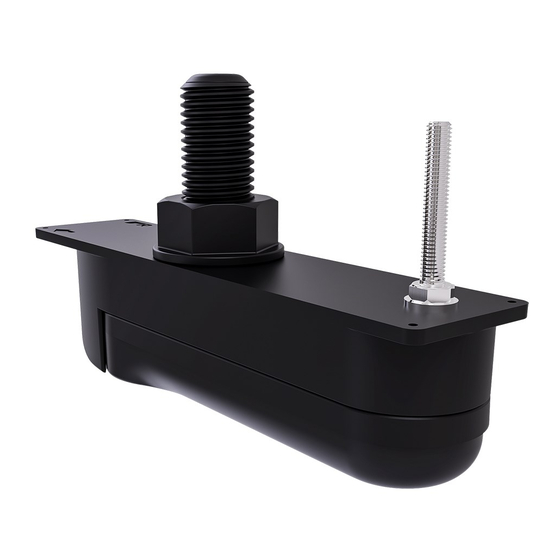
Page 12: Product Overview
2.3 Product overview The HV-300TH series transducers are HyperVision™ thru-hull plastic transducers. Your installation must include either a single HV-300TH, or a split-pair of HV-300THP-P (Port) and HV-300THP-S (Starboard). The transducer is compatible with HyperVision™ variant displays. Note: Plastic thru-hull transducers are recommended for fiberglass and metal hulls and should not be used on vessels with wooden hulls. -
Page 13: Required Additional Components
2.4 Required additional components This product forms part of a system of electronics and requires the following additional components for full operation. • Compatible HyperVision™ sonar-capable device. Refer to p.13 — Compatible displays , for a list of compatible products. •... -
Page 14: Parts Supplied
2.5 Parts supplied The following parts are supplied with each HV-300 series transducer: Unpack your product carefully to prevent damage or loss of parts. Check the box contents against the list below. Retain the packaging and documentation for future reference. Item Description Anti-rotation nut... - Page 15 Item Description 1 x “Y-cable” adapter for connecting a split pair of transducers to a HyperVision™ compatible display. Cable length: 0.3 m (0.98 ft.) 1 x Extension cable 4 m (13.1 ft). In a split pair transducer configuration, extends the single end of the “Y-cable”...
-
Page 17: Chapter 3 Installation
Chapter 3: Installation Chapter contents • 3.1 Tools required on page 18 • 3.2 Pre-installation test on page 21 • 3.3 Selecting a location on page 22 • 3.4 Mounting on page 27 Installation... -
Page 18: Tools Required
3.1 Tools required The following tools are required to install your transducer: Item Description Power drill 13 mm (1/2 in) wrench or suitable adjustable wrench for anti-rotation nut 44 mm (1 3/4 in) wrench or suitable adjustable wrench for hull nut Half-round file Drill bit for pilot holes 9 mm (11/32 in) drill bit (for anti-rotation hole) -
Page 19: Anti-Fouling
Item Description Band saw (with table tilt) Digital angle finder (if dead rise angle identification is required. Warning: Marine-grade sealant Only use marine-grade neutral cure polyurethane sealants. Do NOT use sealants containing acetate or silicone, which can cause damage to plastic parts. Anti-fouling Where local regulations allow, it is recommended that you coat your transducer using a water-based anti-fouling paint. - Page 20 The anti-fouling paint should be applied in a thin and even coat covering all externally exposed transducer surfaces. You should clean your transducer regularly and re-apply anti-fouling paint every 6 months, or sooner depending on how rapidly organic growth builds up. For guidance on transducer cleaning refer to 6.2 Transducer cleaning For instructions on re-applying anti-fouling paint refer to...
-
Page 21: Pre-Installation Test
> Transducer). 6. Check that accurate depth and temperature readings are displayed. 7. If you experience difficulties obtaining readings then contact Raymarine Technical Support. Warning: Transducer operation Only test and operate the transducer in the water. Do NOT operate out of water as overheating may occur. -
Page 22: Selecting A Location
3.3 Selecting a location Warnings and cautions Important: Before proceeding, ensure that you have read and understood the warnings and cautions provided in the Chapter 1 Important information section of this document. Location requirements Follow the guidelines below when selecting a location for your single transducer or split-pair transducers. - Page 23 • When installing split-pair transducers, the fairing block must be cut to the dead rise angle of the hull, ensuring that the transducer elements point straight down. • When fitting to a hull with a keel, ensure that the transducer beam will not be obstructed by the keel.
- Page 24 Item Description Port-side split-pair transducer cable Green Starboard-side split-pair transducer cable Item Description Vessel bow arrow on top face of transducer Element angle or side: (port, “P”; starboard, “S”) Single (all-in-one) transducers are marked “0°” Vessel bow arrow on top face of Fairing block identifier (direction to vessel bow) –...
- Page 25 Product dimensions 30.00 mm (1.18 in) 63.47 mm (2.50 in) 8.00 mm (0.31 in) 55.00 mm (2.17 in) 85.00 mm (3.35 in) 71.88 mm (2.83 in) 148.48 mm (5.85 in) 63.60 mm (2.50 in) 220.36 mm (8.68 in) 267.00 mm (10.51 in) 59.00 mm (2.32 in) Transducer cable length The length of the cable fitted to the transducer is:...
-
Page 26: Emc Installation Guidelines
85.00 mm (3.35 in) 22.20 mm (0.87 in) EMC installation guidelines Raymarine equipment and accessories conform to the appropriate Electromagnetic Compatibility (EMC) regulations, to minimize electromagnetic interference between equipment and minimize the effect such interference could have on the performance of your system Correct installation is required to ensure that EMC performance is not compromised. -
Page 27: Mounting
3.4 Mounting Dead rise angle The dead rise angle is the angle of your vessel’s hull measured from the centerline. The transducer can be installed on vessels with a dead rise angle of 0° to 25°. The transducer should not be installed on vessels with a dead rise angle greater than 25°. - Page 28 Item Description Bespoke ‘L’ shaped cutting guide (not supplied) 4 x screws (not supplied) Fairing block (supplied) Cutting the fairing block The fairing block must be cut to the angle and shape of your hull as shown below. Example port and starboard dead rise angles Item Description Vessel hull (viewed from the rear)
- Page 29 Example fairing block cutting (for starboard side) Item Description Distance between cutting guide and blade. Parallel to waterline Fairing block (viewed from the rear) Dead rise angle (0° to 25°) Example dead rise of hull 1. Calculate the dead rise angle. The dead rise angle should be measured on the outside of the hull from the location that the transducer is to be mounted using an angle finder or similar device.
- Page 30 5. Ensure that the cut will be made within the acceptable cutting area of the fairing. Acceptable cutting area Important: Only cut in the area shown colored in the above illustration. Do NOT cut in the hatched areas shown above. 6.
- Page 31 Item Description Band saw Saw blade Fence Fairing block with cutting guide attached Dead rise angle Table tilt Retain the top half of the fairing block as this will provide a level surface inside the hull to tighten the nuts against. 8.
-
Page 32: Mounting The Transducer
Angle Distance Angle Distance 0° 18.5 mm (0.73 in) 13° 12.1 mm (0.48 in) 1° 18.0 mm (0.71 in)) 14° 11.6 mm (0.47 in) 2° 17.5 mm (0.69 in) 15° 11.1 mm (0.44 in) 3° 17.1 mm (0.67 in) 16° 10.6 mm (0.42 in) 4°... - Page 33 Item Description Represents areas where marine-grade sealant is to be applied Plastic hull nut (sealant to be applied to the bottom face) Anti-rotation nut and washer (sealant to be applied to the bottom face of the nut) Fairing block top half (sealant to be applied to the bottom face) Hull cut away view (sealant to be applied all around the anti-rotation bolt hole and transducer stem hole) Fairing block bottom half (sealant to be applied to the top face and up the vertical...
- Page 34 15. Apply a thick bead of marine-grade sealant: i. in a continuous bead, all around the perimeter of the top face of the transducer. ii. all over the top face of the transducer. iii. all around the base of the transducer stem, ensuring that the sealant will protrude approximately 6 mm above the final tightened nut.
- Page 35 29. If required, apply additional marine-grade sealant around the base of the transducer stem and anti-rotation bolt. 30. Guide the transducer cable through the hull nut 31. Apply a continuous, thick bead of marine-grade sealant to the bottom of the plastic hull nut. 32.
- Page 36 Anti-fouling Where local regulations allow, it is recommended that you coat your transducer using a water-based anti-fouling paint. This will help prevent the build-up of organic growth, which can reduce transducer performance. Important: • Before applying water-based anti-fouling paint, check that local environmental rules and regulations do not prohibit the use of anti-fouling paint.
-
Page 37: Chapter 4 Connections
Chapter 4: Connections Chapter contents • 4.1 General cabling guidance on page 38 • 4.2 Cable routing on page 39 • 4.3 Making connections on page 40 Connections... -
Page 38: General Cabling Guidance
• Unless otherwise stated only use cables supplied by Raymarine. • Where it is necessary to use non-Raymarine cables, ensure that they are of correct quality and gauge for their intended purpose. (e.g.: longer power cable runs may require larger wire gauges to minimize voltage drop along the run). -
Page 39: Cable Routing
4.2 Cable routing Cable routing requirements for the transducer cable. Important: To avoid interference, the cable must be routed as far away from VHF radio antenna devices and cables as possible. • Check that the cable is long enough to reach the display it will be connected to. Optional extension cables are available, if required. -
Page 40: Making Connections
4.3 Making connections Follow the steps below to connect the cable(s) to your product. 1. Ensure that the vessel's power supply is switched off. 2. Ensure that the device being connected to the unit has been installed in accordance with the installation instructions supplied with that device. -
Page 41: Chapter 5 System Checks And Troubleshooting
Chapter 5: System checks and troubleshooting Chapter contents • 5.1 Operation instructions on page 42 • 5.2 Troubleshooting on page 43 System checks and troubleshooting... -
Page 42: Operation Instructions
5.1 Operation instructions For detailed operation instructions for your product, refer to the documentation that accompanies your display. All product documentation is available to download from the Raymarine website: www.raymarine.com/manuals. -
Page 43: Troubleshooting
If after referring to this section you are still having problems with your product, please refer to the Technical support section of this manual for useful links and Raymarine Product Support contact details. - Page 44 Possible causes Possible solutions Power source insufficient With the product under load, using a multi-meter, check the power supply voltage as close to the unit as possible to establish actual voltage when the current is flowing. (Check your product’s Technical specification for power supply requirements.) Damaged or fouled Check transducer condition, ensuring it is not damaged and is free transducer...
-
Page 45: Resetting The Sonar
Possible causes Possible solutions can cause the Fishfinder applications to stop scrolling or the unit to reset/turn off), replace if necessary. Transducer location • Check that the transducer has been installed in accordance with the instructions provided with the transducer. •... -
Page 47: Chapter 6 Maintenance
Chapter 6: Maintenance Chapter contents • 6.1 Routine checks on page 48 • 6.2 Transducer cleaning on page 49 • 6.3 Re-applying anti-fouling paint on page 50 Maintenance... -
Page 48: Routine Checks
6.1 Routine checks The following periodic checks should be made: • Examine cables for signs of damage, such as chafing, cuts or nicks. • Check that the cable connectors are firmly attached and that their locking mechanisms are properly engaged. Note: Cable checks should be carried out with the power supply switched off. -
Page 49: Transducer Cleaning
6.2 Transducer cleaning You must clean your transducer regularly to remove organic growth. Organic growth can build up quickly on the bottom face of your transducer; this can impact transducer performance in a matter of weeks. Important: • When cleaning growth from an anti-fouled transducer, take care not to let paint dust and other debris enter the water, as this can have an impact on aquatic life. -
Page 50: Re-Applying Anti-Fouling Paint
6.3 Re-applying anti-fouling paint If you have applied anti-fouling paint to your transducer, it is important to re-apply it at least every 6 months, to maintain effectiveness. Follow the instructions below to re-apply anti-fouling paint. Important: • Following environmental best practice, preparation and re-application of the anti-fouling paint should be performed using suitable washdown facilities, which ensures paint particles do not enter the water and impact aquatic life. -
Page 51: Chapter 7 Technical Support
Chapter 7: Technical support Chapter contents • 7.1 Raymarine product support and servicing on page 52 • 7.2 Learning resources on page 54 Technical support... -
Page 52: Raymarine Product Support And Servicing
You can obtain this product information using diagnostic pages of the connected MFD. Servicing and warranty Raymarine offers dedicated service departments for warranty, service, and repairs. Don’t forget to visit the Raymarine website to register your product for extended warranty benefits: http://www.raymarine.co.uk/display/?id=788. Region... - Page 53 • Tel: +358 (0)207 619 937 Norway • E-Mail: support.no@raymarine.com (Raymarine subsidiary) • Tel: +47 692 64 600 Denmark • E-Mail: support.dk@raymarine.com (Raymarine subsidiary) • Tel: +45 437 164 64 Russia • E-Mail: info@mikstmarine.ru (Authorized Raymarine distributor) • Tel: +7 495 788 0508 Technical support...
-
Page 54: Learning Resources
7.2 Learning resources Raymarine has produced a range of learning resources to help you get the most out of your products. Video tutorials Raymarine official channel on YouTube: • YouTube LightHouse™ 3 tips and tricks: • Raymarine website Video Gallery: •... -
Page 55: Chapter 8 Technical Specification
Chapter 8: Technical specification Chapter contents • 8.1 Technical specification on page 56 Technical specification... -
Page 56: Technical Specification
8.1 Technical specification Physical specification Overall dimensions • Length: 267.01 mm (10.51 in) (including fairing): • Height: 170.36 mm (6.71 in) including cable bend radius • Width: 63.60 mm (2.50 in) Cable length: • HV-300TH: 6 m (19.69 ft) fitted cable •... -
Page 57: Conformance Specification
Conformance specification Conformance • EN 60945:2002 • IEC 28846:1993 • EMC Directive 2014/30/EU • Australia and New Zealand: C-Tick, Compliance Level 2 Technical specification... -
Page 59: Chapter 9 Spares And Accessories
Chapter 9: Spares and accessories Chapter contents • 9.1 Spares on page 60 • 9.2 Accessories on page 61 Spares and accessories... -
Page 60: Spares
9.1 Spares Description Part number HV-300THP-P Thru-hull plastic transducer R70725 HV-300THP-S Thru-hull plastic transducer R70726 HV-300TH / HV-300THP-P / HV-300THP-S R70741 fairing block... -
Page 61: Accessories
9.2 Accessories Description Part number HyperVision™ transducer extension cable 4 m A80562 (13.12 ft) HV-300THP-P / HV-300THP-S ‘Y’ splitter cable A80605 0.3 m (0.98 ft) Spares and accessories... - Page 63 Index Compatible displays ..........13 Location requirements ..........22 Accessories ............60–61 Anti-fouling ..........19, 36, 50 Maintenance.............. 7 Mounting the transducer .........32 Band saw..............31 Operation instructions ........10, 42 Cable extension ............39 Cable protection............38 Parts supplied............14 Cable routing............39 Product overview............. 12 Cables ..............14 Product recycling (WEEE) ..........
- Page 66 Raymarine Marine House, Cartwright Drive, Fareham, Hampshire. PO15 5RJ. United Kingdom. Tel: +44 (0)1329 246 700 www.raymarine.com a brand by...
Need help?
Do you have a question about the HYPERVISIONT HV-300 Series and is the answer not in the manual?
Questions and answers