Table of Contents
Advertisement
by
A s s e m b l y
O W N E R ' S
by
1 0
&
®
Table of Contents
Dimensions. . . . . . . . . . . . . . . . . . . . . . . . . . . p. 2
Reference Drawings. . . . . . . . . . . . . . . . . . . p. 3
Important Safety Instructions. . . . . . . . . . . p. 4
Before You Begin. . . . . . . . . . . . . . . . . . . . . . p. 5
Preparations. . . . . . . . . . . . . . . . . . . . . . . . . . p. 6
Assembly Instructions. . . . . . . . . . . . . . . . . p. 7-25
®
Accessories. . . . . . . . . . . . . . . . . . . . . . . . . . p. 26-27
Warning, Safety & Maintenance. . . . . . . . . p. 28-31
Exercise Tips. . . . . . . . . . . . . . . . . . . . . . . . . p. 32-51
Mainframe Parts List. . . . . . . . . . . . . . . . . . . p. 52
Hardware List. . . . . . . . . . . . . . . . . . . . . . . . . p. 52-53
Hardware (To Scale). . . . . . . . . . . . . . . . . . . p. 54-57
0 7
o n
s i
e r
Exploded View Diagram. . . . . . . . . . . . . . . . p. 58-59
I n s t r u c t i o n s
M A N U A L
by
GDCC250.1
®
V
v. 091010
Advertisement
Table of Contents

Related Manuals for Body Solid GDCC250.1


Summary of Contents for Body Solid GDCC250.1
- Page 1 ® GDCC250.1 ® Table of Contents Dimensions......p. 2 Reference Drawings....p. 3 Important Safety Instructions.
-
Page 2: Dimensions
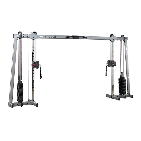
D i m e n s i o n s D i m e n s i o n s The room layout diagram below will help you decide the best placement for your GDCC250. The dimensions of the GDCC250 are: Width 2’ 5” X Length 13'7". The ceiling height requirement for the GDCC250 is 6’11". The usage space is: Width 5’... -
Page 3: Reference Drawings
R e f e r e n c e R e f e r e n c e D r a w i n g s D r a w i n g s G D C C 2 5 0 G D C C 2 5 0 G D C C 2 5 0 R e f e r e n c e... -
Page 4: Important Safety Instructions
I m p o r t a n t S a f e t y I n s t r u c t i o n s Before beginning any fitness program, you should obtain a complete physical examination from your physician. Il est conseille de subir un examen medical complet avant d’entreprendre tout programme d’exercise. -
Page 5: Before You Begin
B e f o r e Y o u B e g i n Thank you for purchasing the GDCC250. This gym is part of the Body-Solid line of quality strength training machines, which let you target specific muscle groups to achieve better muscle tone and overall body conditioning. -
Page 6: Preparations
P r e p a r a t i o n s CAUTION: To set up this unit, you will need assistance. Do not attempt assembly by yourself. You must review and follow the instructions in this Owner’s Manual. If you do not assemble and use the GDCC250 according to these guidelines, you could void the Body-Solid warranty. -
Page 7: Assembly Instructions
A s s e m b l y I n s t r u c t i o n s Assembly of the GDCC250 takes professional installers about 2 hours to complete. If this is the first time you have assembled this type of equipment, plan on significantly more time. - Page 8 S T E P Be careful to assemble all components in the sequence they are presented. S T E P S T E P S T E P S T E P Finger tighten all hardware in this step unless otherwise noted. Be careful to assemble all components Be careful to assemble all components Be careful to assemble all components...
- Page 9 S T E P STEP Above shows STEP 1 assembled and completed Above shows Step 1 assembled and completed. ve shows STEP 1 embled and completed Insert tension cable before installing upper pulley 26. Insert tension cable before instal Insert upper pulley 26 Crossover Cable (36) before installing Upper...
- Page 10 S T E P Be careful to assemble all components in the sequence they are presented. Finger tighten all hardware in this step unless otherwise noted. RIGHT SIDE ASSEMBLY Insert Upright Frame (F) into Base Frame (A) and secure using: Two 8 (M8x15 hex head bolt) Two 9 (M8x20 hex head bolt) Two 20 (M8 arc washer)
- Page 11 S T E P S T E P S T E P Pulley #3 Pulley #6 Above shows STEP 2 assembled and completed Above shows Step 2 assembled and completed. ve shows STEP 2 embled and completed Pre-Drilled Holes RIGHT SIDE ASSEMBLY PAGE 6...
- Page 12 S T E P Be careful to assemble all components in the sequence they are presented. Finger tighten all hardware in this step unless otherwise noted. RIGHT SIDE ASSEMBLY Insert Pulley (25) into Top Frame (B) and secure using: One 4 (M10x65 hex head bolt) One 13 (M10 nylon nut) Two 28 (steel bushing) Insert Pulley (27) into Top Frame (B) and secure using:...
- Page 13 S T E P S T E P S T E P For 260 lb Weight Use Weight Stack Risers (50). For 310 lb Weight Omit Weight Stack Risers (50). W A R N I N G Pulley Holder (54) must be threaded a minimum of 1/2” into the Selector Rod (53), and Jam Nut (15) tightened securely against Spring Lock Washer (23) to ensure proper connection.
- Page 14 S T E P Be careful to assemble all components in the sequence they are presented. Finger tighten all hardware in this step unless otherwise noted. RIGHT SIDE ASSEMBLY S T E P S T E P S T E P S T E P Be careful to assemble all components Be careful to assemble all components...
- Page 15 S T E P S T E P Pulley #3 Pulley #6 Pulley #2 Pulley #5 START HERE Pulley #1 Pulley #4 Strip cable before Strip Cable inserting Rid skin of the line (36) before inserting. Pulley #7 RIGHT SIDE ASSEMBLY PAGE 8...
- Page 16 S T E P Be careful to assemble all components in the sequence they are presented. S T E P S T E P S T E P S T E P Finger tighten all hardware in this step unless otherwise noted. Be careful to assemble all components Be careful to assemble all components Be careful to assemble all components...
- Page 17 S T E P S T E P Insert Crossover Cable (36) before installing Upper Pulley (26). Above shows STEP 4 assembled and completed Insert tension cable before installing upper pulley 26 ove shows STEP 4 Above shows Step 5 assembled and completed. sembled and completed Insert tens cable before in...
- Page 18 S T E P Be careful to assemble all components in the sequence they are presented. Finger tighten all hardware in this step unless otherwise noted. LEFT SIDE ASSEMBLY Insert Upright Frame (F) into Base Frame (A) and secure using: Two 8 (M8x15 hex head bolt) Two 9 (M8x20 hex head bolt) Two 20 (M8 arc washer)
- Page 19 S T E P S T E P S T E P Pulley #3 Pre-Drilled Holes Above shows STEP 5 assembled and completed Above shows STEP 5 Above shows Step 6 assembled and completed. assembled and completed Pulley #6 LEFT SIDE ASSEMBLY PAGE 9...
- Page 20 S T E P Be careful to assemble all components in the sequence they are presented. Finger tighten all hardware in this step unless otherwise noted. LEFT SIDE ASSEMBLY Insert Pulley (25) into Top Frame (B) and secure using: One 4 (M10x65 hex head bolt) One 13 (M10 nylon nut) Two 28 (steel bushing) Insert Pulley (27) into Top Frame (B) and secure using:...
- Page 21 S T E S T E P S T E P For 260 lb Weight Use Weight Stack Risers (50). For 310 lb Weight Omit Weight Stack Risers (50). W A R N I N G Pulley Holder (54) must be threaded a minimum of 1/2” into the Selector Rod (53), and Jam Nut (15) tightened securely against Spring Lock Washer (23) to ensure proper connection.
- Page 22 S T E P Be careful to assemble all components in the sequence they are presented. Finger tighten all hardware in this step unless otherwise noted. LEFT SIDE ASSEMBLY S T E P S T E P S T E P S T E P Be careful to assemble all components Be careful to assemble all components...
- Page 23 S T E P S T E P Pulley #5 Pulley #6 Pulley #3 Pulley #2 Pulley #1 START HERE Pulley #4 Strip Cable (36) before l i n Rid skin of the line inserting. Rid skin of the line Pulley #7 LEFT SIDE ASSEMBLY...
- Page 24 S T E P Be careful to assemble all components in the sequence they are presented. Finger tighten all hardware in this step unless otherwise noted. Face the Left Side and Right Side of the GDCC250 towards each other as shown in the diagram.
- Page 25 S T E P S T E P S T E P Above shows STEP 8 assembled and completed Above shows STEP 8 Above shows Step 9 assembled and completed. assembled and completed Left Side Right Side PAGE 12...
-
Page 26: Accessories
A c c e s s o r i e s Accessory Installation The GDCC250 comes equipped with 2 accessories: 1) Handle Strap 2) Ankle Strap The diagrams on the following page show the proper installation of the above accessories. Use the provided Snap Links to properly connect the accessories to your BodySolid gym. - Page 27 A c c e s s o r i e s 13 19 31X2 26X2 14X2 Insert tension 17X4 cable before installing upper pulley 26 Diagram 2 31X2 26X2 Ankle Strap Installation nside 14X2 17X4 Insert tension Diagram 1 13X2 cable before installing Handle Installation upper pulley 26...
-
Page 28: Warning, Safety & Maintenance
W a r n i n g , S a f e t y & M a i n t e n a n c e W a r n i n g , S a f e t y & M a i n t e n a n c e Be sure that all users carefully read and understand all warning, safety and maintenance labels on the machine before each use. - Page 29 W a r n i n g , S a f e t y & M a i n t e n a n c e Warning Safety and Maintenance of Cables Although Body-Solid provides the highest quality of materials and workmanship in its products, the fact remains that component parts eventually wear out over time and with use.
- Page 30 W a r n i n g , S a f e t y & M a i n t e n a n c e CABLES: Precision craftsmanship assures Body-Solid’s ability to consistently deliver products of the highest standards. Our m While the machine is not in use, carefully run your products have been carefully designed to ensure safe, ef- fingers along the cable to feel for thinning or bulging...
- Page 31 W a r n i n g , S a f e t y & M a i n t e n a n c e MAINTENANCE DAILY WEEKLY LATEST DATE ENTRY SCHEDULE � CABLES: CHECK TENSION, END FITTINGS, AND COATING.
- Page 32 PHRASES, TERMS, TIPS & GUIDELINES B E G I N N E R ’ S G U I D E L I N E S • Work out at least two times a week. • Include six to eight exercises that train major muscle groups. •...
- Page 33 PHRASES, TERMS, TIPS & GUIDELINES S T A R T I N G R E S I S T A N C E L E V E L If you begin weight training at too high a level, you risk serious injury. You will also develop poor form, which will hinder your efforts and discourage you.
- Page 34 NUTRITION Good nutrition is a diet in which foods are eaten in directly related to increased cardiovascular disease. a decrease in the total amount of bone mineral in the proper quantities and with the needed distribution of Unsaturated fats are typically liquid at room temperature. body and by a decrease in strength of the remaining nutrients to maintain good health.
- Page 35 EXERCISE PRESCRIPTION Sets Rest Periods Between Workouts Sets are defined as a combination of any number of reps of one exercise. The number The amount of rest between training sessions depends on the recovery ability of the of sets used in a workout is directly related to training results. Typically, two to three sets individual.
-
Page 36: Training Tips
TRAINING TIPS FOR BEGINNER’S A R E Y O U “ B E G I N N E R ” ? A beginner can be classified as someone who has never touched a weight, may have lifted for a while, but has taken a substantial amount of time off, or has not consistently trained over the last six months. - Page 37 COMMON TRAINING MISTAKES 1. Lack of Adequate Warm-Up and Inadequate Flexibility A warmed muscle is a more flexible muscle that’s better able to lift heavier weights and work in a full range of motion. Those warmed muscles also greatly reduce your chance of training injuries. 2.
- Page 38 SETTING UP YOUR PERSONAL PROGRAM It is important to first establish specific Once you have determined your personal goals, you will need to set up a schedule and realistic goals. You should determine that helps you attain them. Set up a schedule that includes the number of workouts your long term goal and then set a per week, the type of workout activity, the time of day for each workout, and the actual series of short term goals that will...
- Page 39 DETERMINE YOUR TRAINING METHOD Which training method is right for you? There are three basic types of weight training methods: 1. Training for muscular FOR MUSCULAR FOR STRENGTH FOR POWER endurance and definition ENDURANCE & DEFINITION AND MUSCLE MASS 2. Training for strength This training method incorporates This type of training is the most This is the method most often used by...
-
Page 40: Exercise Tips
EXERCISETIPS Listed below are Body-Solid’s picks of the best exercises you can do for each body part. These exercises can be done using free weights, machines and multi-station gyms. Learn to do each exercise in proper form. You can make substitutions in your training and try variations of each using different Body-Solid grips, cable attachments and accessories to slightly change the emphasis of a particular exercise. - Page 41 ANATOMY CHART FRONT VIEW Note: These illustrations depicting exaggerated musculature are Chest not in the textbook anatomical position. As such, they are inexact Neck Pectoralis Major for medical purposes but are useful for a general understanding. Omohyoid Pectoralis Minor Sternohyoid (beneath major) •...
-
Page 46: Cool Down
STRETCHING & FLEXIBILITY Flexibility is an important component of physical fitness and needs to be addressed in a resistance training program. The two main purposes for stretching are injury prevention and a faster rate of recovery from exercise. Stretching should be performed in both the warm up and cool down phases of a training session. - Page 47 STRETCHING STRETCHING STRETCHING STRETCHING STRETCHING STRETCHING STRETCHING STRETCHING STRETCHING WARM-UP/COOL-DOWN WARM-UP/COOL-DOWN WARM-UP/COOL-DOWN WARM-UP/COOL-DOWN WARM-UP/COOL-DOWN WARM-UP/COOL-DOWN WARM-UP/COOL-DOWN WARM-UP/COOL-DOWN WARM-UP/COOL-DOWN UPPER BACK Cross Arm in Front of Chest MUSCLE(S) AFFECTED: latissimus dorsi and teres major 1. Stand or sit with the right arm slightly flexed (15° to 30°) and adducted across the chest.
- Page 48 STRETCHING STRETCHING STRETCHING STRETCHING STRETCHING STRETCHING STRETCHING STRETCHING STRETCHING WARM-UP/COOL-DOWN WARM-UP/COOL-DOWN WARM-UP/COOL-DOWN WARM-UP/COOL-DOWN WARM-UP/COOL-DOWN WARM-UP/COOL-DOWN WARM-UP/COOL-DOWN WARM-UP/COOL-DOWN WARM-UP/COOL-DOWN SIDES Side Bend with Straight Arms MUSCLE(S) AFFECTED: external oblique, latissimus dorsi and serratus anterior 1. Stand with feet 14 to 16 inches apart. Stretching 2.
- Page 49 STRETCHING STRETCHING STRETCHING STRETCHING STRETCHING STRETCHING STRETCHING STRETCHING STRETCHING WARM-UP/COOL-DOWN WARM-UP/COOL-DOWN WARM-UP/COOL-DOWN WARM-UP/COOL-DOWN WARM-UP/COOL-DOWN WARM-UP/COOL-DOWN WARM-UP/COOL-DOWN WARM-UP/COOL-DOWN WARM-UP/COOL-DOWN Stretching the hamstrings with POSTERIOR OF THIGH emphasis on insertion of the hamstrings and calves. Sitting Toe Touch MUSCLE(S) AFFECTED: hamstrings, spinal erectors and gastrocnemius 1.
- Page 50 STRETCHING STRETCHING STRETCHING STRETCHING STRETCHING STRETCHING STRETCHING STRETCHING STRETCHING WARM-UP/COOL-DOWN WARM-UP/COOL-DOWN WARM-UP/COOL-DOWN WARM-UP/COOL-DOWN WARM-UP/COOL-DOWN WARM-UP/COOL-DOWN WARM-UP/COOL-DOWN WARM-UP/COOL-DOWN WARM-UP/COOL-DOWN GROIN Straddle (Spread Eagle) Stretching the hamstrings and groin with emphasis on insertion of MUSCLE(S) AFFECTED: gastrocnemius, hamstrings, spinal erectors, the hamstrings and calves adductors and sartorius 1.
- Page 51 STRETCHING STRETCHING STRETCHING STRETCHING STRETCHING STRETCHING STRETCHING STRETCHING STRETCHING WARM-UP/COOL-DOWN WARM-UP/COOL-DOWN WARM-UP/COOL-DOWN WARM-UP/COOL-DOWN WARM-UP/COOL-DOWN WARM-UP/COOL-DOWN WARM-UP/COOL-DOWN WARM-UP/COOL-DOWN WARM-UP/COOL-DOWN POSTERIOR OF LOWER LEG Step Stretch MUSCLE(S) AFFECTED: gastrocnemius and soleus; also, achilles tendon 1. Have ready a step or board 3 to 4 inches high. 2.
-
Page 52: Mainframe Parts List
M a i n f r a m e P a r t s L i s t Part# Description BASE FRAME TOP FRAME CROSS FRAME WITH INSERT HANDLE CROSS FRAME UPRIGHT FRAME GUIDE POST PULL UP BAR LARGE STABILIzER FRAME SMALL STABILIzER FRAME H a r d w a r e L i s t HEx HEAD BOLT... -
Page 53: Hardware List
H a r d w a r e L i s t Part# Description NYLON BUSHING M60x50 (9211-033) ShAft CollAr Φ 3/4” (9211-046) END CAP (9211-114) FOOT CAP (9211-117) ruBBer Donut Φ55 (9310-027) STEEL CABLE 7540 mm Steel BuShing Φ16 x Φ10.2 x 26.5L (8530-019) WEIGHT STACK PIN LANYARD (F920003) HANDLE (9630-125) - Page 54 H a r d w a r e ( T o S c a l e ) GDCC200 HARDWARE GDCC200 HARDWARE GDCC200 HARDWARE GDCC200 HARDWARE GDCC200 HARDWARE GDCC200 HARDWARE (shown in actual size) (shown in actual size) (shown in actual size) (shown in actual size) (shown in actual size) (shown in actual size)
- Page 55 H a r d w a r e ( T o S c a l e ) Weight Stack Pin (8250-071) Weight Stack Pin (8250-071) ...2PCS ...2PCS Weight Stack Pin (8250-071) Weight Stack Pin (8250-071) Weight Stack Pin (8250-071) Weight Stack Pin (8250-071) ...2PCS ...2PCS Weight Stack Pin (8250-071)
- Page 56 H a r d w a r e ( T o S c a l e ) GDCC200 HARDWARE GDCC200 HARDWARE GDCC200 HARDWARE GDCC200 HARDWARE (shown in actual size) (shown in actual size) (shown in actual size) (shown in actual size) GDCC200 HARDWARE GDCC200 HARDWARE GDCC200 HARDWARE...
- Page 57 GDCC200 HARDWARE H a r d w a r e ( T o S c a l e ) (shown in actual size) GDCC200 HARDWARE (shown in actual size) Part# 23 Spring Washer Qty. 2 . 1/2” Spring Washer... ID) Washer... 1/2”...
-
Page 58: Exploded View Diagram
E x p l o d e d V i e w D i a g r a m EXPL C3 B2 B2 C3 17 14 connects to connects to connects to connects to Match the letters inside connects to each triangle connects to connects to... - Page 59 EXPLODED VIEW DIAGRAM GDCC250.1 17 14 17 14 19 3 34 19 13 19 13 19...
- Page 60 ® 1900 S. Des Plaines Ave. Forest Park, Il 60130 1 (800) 556-3113 Hours: M-F 8:30 - 5:00 www.bodysolid.com Copyright 2009. Body-Solid. All rights reserved. Body-Solid reserves the right to change design and specifications when we feel it will improve the product. Body-Solid machines maintain several patented and patent pending features and designs.
Need help?
Do you have a question about the GDCC250.1 and is the answer not in the manual?
Questions and answers