Table of Contents
Advertisement
U S E R G U I D E
UGD024/0304
D Carousel Dryer - DC-1
Models 15, 25, 50, 75, and 100 with DC-1 Controls
INTRODUCTION
•
Purpose of the User Guide
Read this so no one gets hurt
Typical applications
•
How it works
installation
•
Mounting the dryer and hopper on a Processing Machine
hopper on the throat
•
Mounting the dryer on the floor stand; Hopper on the throat
the mobile floor stand
•
•Connecting water hoses
•
•
The DC-1 dryer control panel
drying
•
Using the auto start countdown function
Corporate Office: 412.312.6000
•
How the guide is organized
•
How to use the lockout device
•
Specifications: D Dryer
Connecting the main power
Connecting the RTD probe
•
D dryer DC-1 control functions
•
Setting high and low setpoint limits
l
Instant Access 24/7 (Parts and Service): 800.458.1960
•
Your responsibilities as a user
•
DESCRIPTION
•
INSTALLATION
•
Positioning the dryer on the floor; Mounting the
•
Checking for proper air flow
•
Mounting a loader on the hopper
•
Control Function Description
www.conairnet.com
•
•
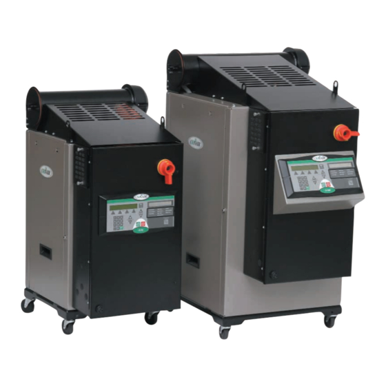
What is the D Carousel Dryer?
•
Unpacking the boxes
•
•
Mounting the dryer and hopper on
•
Connecting the air hoses
•
OPERATION
•
How it works
• To
start drying
•
M A I N T E N A N C E
l
Parts and Service: 814.437.6861
ATTENTION:
•
Preparing for
•
To stop
Advertisement
Chapters
Table of Contents

Related Manuals for Conair 100


Summary of Contents for Conair 100
- Page 1 U S E R G U I D E UGD024/0304 D Carousel Dryer - DC-1 Models 15, 25, 50, 75, and 100 with DC-1 Controls INTRODUCTION • Purpose of the User Guide Read this so no one gets hurt •...
- Page 2 Serial Number(s): Model Number(s): DISCLAIMER: The Conair Group, Inc., shall not be liable for errors contained in this User Guide or for incidental, consequential damages in connection with the furnishing, performance or use of this information. Conair makes no warranty of any kind with regard to this information, including,...
-
Page 3: Table Of Contents
Ta b l e o f C o n t e n t s I n t r o d u c t i o n Purpose of the User Guide ......1-2 How the guide is organized . - Page 4 Checking for proper air flow ......3-12 Connecting the air hoses ......3-15 Connecting water hoses.
- Page 5 Tr o u b l e s h o o t i n g Before beginning ........6-2 A few words of caution .
- Page 6 A p p e n d i x Installing an aftercooler (optional) ......C-1 Cleaning the aftercooler ....... C-3 A p p e n d i x Installing the flow control (optional) .
- Page 7 The MDC control panel ....... G-12 MDC control functions ....... G-12 To start drying .
- Page 8 l Ta b l e o f C o n t e n t s...
- Page 9 S E C T I O N I n t r o d u c t i o n P u r p o s e o f t h e u s e r g u i d e ... . . 1 - 2 H o w t h e g u i d e i s o r g a n i z e d .
-
Page 10: I N T R O D U C T I O N
P u r p o s e o f t h e U s e r G u i d e This User Guide describes the Conair D series of carousel dehumidifying dryers and explains step-by-step how to install, operate, maintain and repair this equipment. -
Page 11: Using The D Series As A Central Dryer
U s i n g t h e D S e r i e s a s a C e n t r a l D r y e r This manual incorporates the information necessary to use the Conair D series dryer as a central dryer. Throughout this manual, information particular to cen- tral dyer application of the D series dryer is called out by the following treat- ment. -
Page 12: At T E N T I O N
AT T E N T I O N : R e a d t h i s s o n o o n e g e t s h u r t We design equipment with the user’s safety in mind. You can avoid the potential hazards identified on this machine by following the procedures outlined below and elsewhere in the User Guide. -
Page 13: How To Use The Lockout Device
A lockable device has been provid- ed to isolate this product from potentially hazardous electricity. Lockout is the preferred method of isolating machines or equipment from energy sources. Your Conair product is equipped with the lockout device pictured below. To use the lockout device: Stop or turn off the equipment. - Page 14 1 - 6 l I n t r o d u c t i o n...
-
Page 15: D E S C R I P T I O N
S E C T I O N D e s c r i p t i o n W h a t i s t h e D c a r o u s e l d r y e r ? ..2 - 2 Ty p i c a l a p p l i c a t i o n s . -
Page 16: What Is The D Carousel Dryer
The D dryer can be mounted beside the hopper on the throat of a processing machine using the optional diving board support frame, or positioned on the floor near the machine using the standard casters. Two mobile floor stand designs are also available. - Page 17 Low-high (with aftercooler & precooler)* *Note: See instruction on page 4-12 for setpoints over 150°F (66°C). • Throughput rates of 15 to 100 lbs (6.8 to 37.3 kg) per hour (some materials can be run at a higher rate). •...
-
Page 18: How It Works
2 - 4 l D e s c r i p t i o n H o w I t Wo r k s The D carousel dryer achieves continuous, closed loop drying by passing air simul- taneously through two heaters and three tanks of molecular sieve desiccant. ROCESS RYING The process blower pulls moist air from the top of the drying hopper. - Page 19 H o w I t Wo r k s ( c o n t i n u e d ) PROCESS HOPPER RETURN FILTER RETURN AIR DRYER OPTIONS 1 SET BACK TEMPERATURE 2 PROCESS CFM MONITOR 3 PM1 / DEW POINT MONITOR The components identified by this type of box in the drawing are not supplied with the D dryer when it is configured as a central dryer.
- Page 20 Dryers running at 50 HZ will have 17% less airflow, and a 17% reduction in material throughput. Specifications may change without notice. Consult a Conair representative for the most current information. All models 100 - 375° F {38 - 191° C} with options All models -40°...
- Page 21 S p e c i f i c a t i o n s : D C a r o u s e l OPTIONAL HOPPERS AND MOUNTING BRACKET HOPPER MODEL Hopper / Mounting Frame Dimensions inches {cm} Volume ft Capacity lb {kg} @40 lb/ft Mounting Frame Weight lb {kg} Hopper Weight lb {kg}...
- Page 22 2 - 8 l D e s c r i p t i o n...
-
Page 23: I N S T A L L A T I O N
I n s t a l l a t i o n U n p a c k i n g t h e b o x e s ....3 - 2 P r e p a r i n g f o r i n s t a l l a t i o n . -
Page 24: Mounting Hardware
Mounting Hardware: Floor stand option: four 5/16-18 self-locking bolts four hose clamps Support frame option: eight 3/8-16 self-locking bolts four 5/16-18 self-locking bolts four hose clamps NOTE: You must posi- tion the dryer on the floor or mount it to a floor stand if your pro- cessing machine throat opening is 1 inch (2.54... - Page 25 U n p a c k i n g t h e B o x e s Take a moment to record serial numbers and electrical power specifications in the blanks provided on the back of the the User Guide’s title page. The infor- mation will be helpful if you ever need service or parts.
-
Page 26: Preparing For Installation
3 in. (7.62 cm) D-15, D-25 & D-100 3 - 4 l I n s t a l l a t i o n P r e p a r i n g f o r I n s t a l l a t i o n The D carousel dryer is easy to install if you plan the location and prepare the mounting area properly. - Page 27 You can make an adapter using the dimensions provided or purchase one from Conair. 4 inches (10.16 cm) square 3 inches (7.62 cm) square I n s t a l l a t i o n l...
-
Page 28: Tools For Installation
Tools for installation: Flathead screwdriver 9/16” and 1/2” wrench Hoist NOTE: You must position the dryer on the floor or mount it to an optional floor stand if your processing machine throat requires the small discharge assembly or a mounting plate with less than a 3 x 3 in. - Page 29 M o u n t i n g t h e D r y e r a n d H o p p e r o n a P r o c e s s i n g M a c h i n e The drying hopper, slide gate, support frame, and discharge assembly may have been shipped fully assembled.
-
Page 30: Po S I T I O N I N G T H E D R Y E R O N T H E F L O O R ; M O U N T I N G T H E H O P P E R O N T H E T H R O A T
Tools for installation: 9/16” wrench Flathead screwdriver Hoist 3 - 8 l I n s t a l l a t i o n Po s i t i o n i n g t h e D r y e r o n t h e F l o o r ; M o u n t i n g t h e H o p p e r o n t h e T h r o a t WARNING: You are responsible for the structural integrity of this installation. -
Page 31: Mounting The Hopper
M o u n t i n g t h e H o p p e r CAUTION: To prevent accident and injury, lift the empty hopper onto the throat of the processing machine using a hoist and the lifting lugs provided. Also lift the dryer from the shipping container using a hoist and the lifting lugs provided. -
Page 32: Mounting The Dryer On The Floor Stand; Hopper On The Throat
3 - 1 0 l I n s t a l l a t i o n M o u n t i n g t h e D r y e r o n t h e F l o o r S t a n d ;... - Page 33 C o n n e c t i n g t h e M a i n Po w e r Connect the power wires to the three terminals at the top of the power discon- nect holder. Connect the ground wire to either grounding point as shown in the photo. ( c o n t i n u e d ) IMPORTANT: Always refer to the wiring diagrams that came with...
-
Page 34: Checking For Proper Air Flow
C h e c k i n g f o r P r o p e r A i r F l o w This step is only needed on 50, 75, and 100 models if the phase detection option was not ordered with the dryer. - Page 35 ( c o n t i n u e d ) Start Return Air Inlet Moisture exhaust Delivery air outlet (15, 25, and 50 models) Delivery air outlet (75 and 100 models) I n s t a l l a t i o n l 3 - 1 3...
- Page 36 C h e c k i n g f o r P r o p e r A i r F l o w INSTALLATION NOTE: Models 50, 75, and 100 These models use a three-phase process blower. If the dryer shuts down and a Process Loop Break shutdown alarm is indicated within the first few minutes of operation, check for proper air flow.
-
Page 37: Connecting Water Hoses
Return Air Inlet Delivery air outlet (75 and 100 models) NOTE: Do not allow the flexible hoses to kink or crimp. I n s t a l l a t i o n l 3 - 1 5... -
Page 38: Connecting The Rtd Probe
Central When configured as a central dryer, moni- toring the drying air temperature is not necessary since there is no process heater in the system. Therefore, installa- tion and connection of this RTD probe is not applicable. 3 - 1 6 l I n s t a l l a t i o n C o n n e c t i n g t h e RT D P r o b e The RTD probe monitors the temperature of the drying air as it enters the hopper. -
Page 39: Mounting A Loader On The Hopper
M o u n t i n g a L o a d e r o n t h e H o p p e r If you have a Conair loader or vacuum receiver, you can use the flange and mounting clips provided on the top of the hopper. -
Page 40: Troubleshooting
3 - 1 8 l I n s t a l l a t i o n Te s t i n g T h e I n s t a l l a t i o n Press the START button. If everything is installed correctly: •... - Page 41 O p e r a t i o n h e D C - 1 d r y e r c o n t r o l p a n e l ... 4 - 2 D d r y e r D C - 1 c o n t r o l f u n c t i o n s .
-
Page 42: The Dc-1 Dryer Control Panel
I n c r e m e n t / D e c r e m e n t B u t t o n s Used to increase or decrease values. Shutdown Alarms A l a r m A1 Process High Temp. A2 Process Loop Break A3 Process Heater High Temp. -
Page 43: D Dryer Dc-1 Control Functions
D D r y e r D C - 1 C o n t r o l F u n c t i o n s Dryer functions are values that you can set or monitor. Press the Scroll button until the function you want to set or monitor appears in the LED display. -
Page 44: Test Mode
25 5 sec 09.5 1 sec 01.0 1 sec 250 Process Temp Default Screen 425 Regen Temp 100 Return Air Temp Auto Start ----- Load Time (MDC) 120 Activate Setback Temp (Option) 250 Setback Temp Process (Option) 7 Setback Load Rate (Option) -
Page 45: Control Function Descriptions
C o n t r o l F u n c t i o n D e s c r i p t i o n s S c r e e n SCREEN 1 SCREEN 2 SCREEN 3 09.5 SCREEN 4 01.0 SCREEN 5 (Default Screen) -
Page 46: C O N T R O L F U N C T I O N D E S C R I P T I O N S
Central When supplied for central drying appli- cations, this function is not available. 4 - 6 l O p e r a t i o n C o n t r o l F u n c t i o n D e s c r i p t i o n s S c r e e n SCREEN 7 SCREEN 8... - Page 47 C o n t r o l F u n c t i o n D e s c r i p t i o n s S c r e e n SCREEN 10 (Setback Temperature Option) SCREEN 11 (Setback Options) SCREEN 12 (Setback Load Rate Option) ( c o n t i n u e d )
- Page 48 4 - 8 l O p e r a t i o n C o n t r o l F u n c t i o n D e s c r i p t i o n s S c r e e n SCREEN 13 (PM1 and/or DEW- POINT MONITOR Options)
- Page 49 C o n t r o l F u n c t i o n D e s c r i p t i o n s S c r e e n Screens 15-27 require access code 754. SCREEN 15 (Set up Screen) SCREEN 16 (Set up Screen) SCREEN 17 (Set up Screen) SCREEN 18 (Set up Screen)
- Page 50 Central When supplied for central drying appli- cations, this function is not available. Central When supplied for central drying appli- cations, this function is not available. 4 - 1 0 l O p e r a t i o n C o n t r o l F u n c t i o n D e s c r i p t i o n s S c r e e n Screens 15-27 require access...
- Page 51 C o n t r o l F u n c t i o n D e s c r i p t i o n s S c r e e n Screens 15-27 require access code 754. SCREEN 23 (Set up Screen) Aftercooler Flow Control Option SCREEN 24 (Set up Screen) Setback Temperature Option...
- Page 52 . If the screen is set ° °C) to "On" the control will assume the pre- cooler is connected in the process line and will only allow setpoints from 100 to F (37.8 to 65.5 . The control will ° °C)
- Page 53 C o n t r o l F u n c t i o n D e s c r i p t i o n s S c r e e n Screen 28-43 require access code 755. SCREEN 29 (Test Mode Screen) SCREEN 30 (Test Mode Screen) SCREEN 31 (Test Mode Screen) SCREEN 32 (Test Mode Screen)
- Page 54 4 - 1 4 l O p e r a t i o n C o n t r o l F u n c t i o n D e s c r i p t i o n s S c r e e n Screen 28-43 require access code 755.
- Page 55 C o n t r o l F u n c t i o n D e s c r i p t i o n s S c r e e n Screen 28-43 require access code 755. SCREEN 39 (Test Mode Screen) SCREEN 40 (Test Mode Screen) SCREEN 41 (Test Mode Screen) SCREEN 42 (Test Mode Screen)
- Page 56 4 - 1 6 l O p e r a t i o n C o n t r o l F u n c t i o n D e s c r i p t i o n s S c r e e n Access code 756 required.
-
Page 57: To Start Drying
To S t a r t D r y i n g Make sure there is material in the hopper. Turn on the main power to the dryer disconnect dial is in the ON position. This powers up the con- trol and the display lights will illuminate. -
Page 58: To S T A R T D R Y I N
4 - 1 8 l O p e r a t i o n To S t a r t D r y i n g Press the START button. If everything is installed correctly: • The green light on the start button will illuminate. •... -
Page 59: Auto Start
U s i n g t h e A u t o S t a r t C o u n t d o w n F u n c t i o n The countdown function allows the user to set the D Carousel dryer to automat- ically start at a predetermined time. - Page 60 Central When configured as a central dryer, the high setpoint limits can not be set since there is no process heater in the system. 4 - 2 0 l O p e r a t i o n S e t t i n g t h e H i g h S e t p o i n t L i m i t s You can protect your drying process by preventing someone from entering process temperatures above an acceptable level for the material.
-
Page 61: M A I N T E N A N C E
S E C T I O N M a i n t e n a n c e P r e v e n t a t i v e m a i n t e n a n c e c h e c k l i s t ..5 - 2 C l e a n i n g t h e h o p p e r . -
Page 62: Preventative Maintenance Checklist
5 - 2 l M a i n t e n a n c e P r e v e n t a t i v e M a i n t e n a n c e C h e c k l i s t Routine maintenance will ensure optimum operation and performance of the D Carousel Dryer. -
Page 63: Cleaning The Hopper
C l e a n i n g t h e H o p p e r CAUTION: Hot surfaces. Always protect yourself from hot surfaces inside and out- side the dryer and drying hopper. The hopper, spreader cone, and discharge assembly should be cleaned thoroughly between material changes to prevent resin contamination. -
Page 64: Cleaning The Process Filter
5 - 4 l M a i n t e n a n c e C l e a n i n g t h e P r o c e s s F i l t e r Clogged filters reduce air flow and dryer efficiency. Cleaning frequency depends on how much material you process and how dusty it is. -
Page 65: Cleaning The Aftercooler Coils
C l e a n i n g t h e A f t e r c o o l e r C o i l s If you have the optional aftercooler, you need to clean the cooling coils to keep them working efficiently. - Page 66 5 - 6 l M a i n t e n a n c e...
-
Page 67: Tr O U B L E S H O O T I N G
S E C T I O N Tr o u b l e s h o o t i n g B e f o r e b e g i n n i n g ....6 - 2 A f e w w o r d s o f c a u t i o n . -
Page 68: Before Beginning
6 - 2 l Tr o u b l e s h o o t i n g B e f o r e B e g i n n i n g You can avoid most problems by following the recommended installation and maintenance procedures outlined in this User Guide. -
Page 69: A Few Words Of Caution
Find the wiring and equipment diagrams that were shipped with your dryer. These diagrams are the best reference for correcting a prob- lem. The diagrams also will note any custom features, such as special wiring or alarm capabilities, not covered in this User Guide. A Fe w Wo r d s o f C a u t i o n The D Carousel dryer is equipped with numerous safety devices. -
Page 70: How To Identify The Cause Of A Problem
6 - 4 l Tr o u b l e s h o o t i n g H o w t o I d e n t i f y t h e C a u s e o f a P r o b l e m Most dryer malfunctions are indicated by an illuminated Acknowledge Alarm light on the D carousel dryer control panel. -
Page 71: Shut Down Alarms
S h u t D o w n A l a r m s Central If the red Acknowledge Alarm LED is blinking, the alarm is a shutdown alarm. The dryer will shutdown automatically to prevent damage to the When supplied for central equipment or personnel. - Page 72 Problem Regen Heater High Temperature – The snap switch in the regeneration heater tube activated due to excessive tem- perature. Carousel Index Too Long Alarm – If the carousel index was more than 1.5 times the normal index time, it shuts down the dryer.
- Page 73 S h u t D o w n A l a r m s Problem Possible cause The tubing going to the pressure switch Process Blower Pressure is cut or has come loose. – If the process blower pres- sure switch opens (loss of The process blower overload has tripped.
- Page 74 Central When supplied for central drying applications, these shut down alarms are not available. Problem Process Protection High Temperature – If the process protection temperature exceeds the process protection high temperature setpoint, it shuts down the dryer. Defaults are set to 600°F (315.6°C) for 10 sec.
- Page 75 S h u t D o w n A l a r m s Problem Possible cause Process Blower The process blower has mechanically Overload – The process blower failed or is unable to rotate freely. overload has tripped due to a mechanical or electrical prob- lem.
-
Page 76: Passive Alarms
Central When supplied for central drying applications, these passive alarms are not available. Problem Process Temperature Deviation – The process tem- perature exceeds the deviation band as entered for the speci- fied time. Default values are 43°F (6°C) for 5 sec. Process Low Temperature –... -
Page 77: Pa S S I V E A L A R M
Pa s s i v e A l a r m s Problem Possible cause Return Air High The hopper does not contain enough Temperature – If the return air material. temperature is between 150 and 180°F (65.6 and 82.2°C). You are drying at a high drying tempera- ture (above 250°F [121.1°C]) or running at low throughputs. - Page 78 Problem Process Dew Point (PM1 Option) – The dew point has not fallen below the setpoint. If the dew point goes below the setpoint, the alarm should go away. Note: The alarm is not active for the first 3 indexes Process Filter Clogged (Option) –...
- Page 79 Pa s s i v e A l a r m s Possible cause Problem The MDC blower has mechanically The MDC conveying failed or is unable to rotate freely. blower exceeded the full load amps rating for the blower motor.
- Page 80 Problem Regen RTD Integrity – If the process RTD is faulty. Return Air RTD Integrity Alarm– If the return air RTD is faulty. Out of Hopper RTD Integrity – The dryer continues to run with a passive alarm. 6 - 1 4 l Tr o u b l e s h o o t i n g Pa s s i v e A l a r m s Possible cause...
-
Page 81: Setback
S e t b a c k The setback function available on the DC-1 Dryer is designed to save you money on energy costs and keep you from over drying your material. Setback is available as separate options on both the temperature and load rate setting. This is how setback operates when the control setback is set to "On"... - Page 82 6 - 1 6 l Tr o u b l e s h o o t i n g S e t b a c k ( c o n t i n u e d ) Use Screen 11 to set the temperature setpoint to which the process air will revert to once the air at the outlet of the drying hopper has reached its setpoint.
-
Page 83: Replacing Fuses
R e p l a c i n g F u s e s Disconnect and lockout the main power supply. Open the electrical enclosure door. Check the fuse. If necessary, pull the fuse out and replace it with a fuse of the same type and rating. -
Page 84: Checking Heater Solid State Relays
Regeneration heater solid state relays If ohms equal zero or infinity, replace the contactor. 6 - 1 8 l Tr o u b l e s h o o t i n g C h e c k i n g H e a t e r S o l i d S t a t e R e l a y s Disconnect and lockout the main power supply. -
Page 85: Checking Or Replacing Temperature Sensors
C h e c k i n g o r R e p l a c i n g Te m p e r a t u r e S e n s o r s The D carousel dryer uses RTD sensors to monitor the temperatures of the drying air, the return air, the regeneration exhaust, and the regeneration and process heater boxes. -
Page 86: Adjusting The Limit Switch
6 - 2 0 l Tr o u b l e s h o o t i n g A d j u s t i n g t h e L i m i t S w i t c h Stop the dryer. - Page 87 R e p l a c i n g t h e H e a t e r s R e g e n e r a t i o n H e a t e r Disconnect and lockout the main power. Gain access to the regeneration heater by removing the right dryer side panel.
-
Page 88: Replacing The Heaters
IMPORTANT: The distance the RTD extends into the heater is critical for proper functioning. The distance from the metal heater tube to the outside surface of the curve on the RTD must " be 2.5 (63.5 mm) (see photo). To take the measurement, peel back (but do not remove) any existing insulation to access the metal heater tube. - Page 89 R e p l a c i n g t h e H e a t e r P r o c e s s H e a t e r Disconnect and lockout the main power. Gain access to the process heater by removing the left dryer side panel.
-
Page 90: R E P L A C I N G T H E H E A T E R
Central When configured as a central dryer, there is no process heater in the system. Therefore, replacing the process heater is not applicable. 6 - 2 4 l Tr o u b l e s h o o t i n g R e p l a c i n g t h e H e a t e r P r o c e s s H e a t e r ( c o n t i n u e d ) -
Page 91: Replacing The Desiccant Tanks
The D Carousel Dryer has refillable desiccant tanks. When desiccant becomes clogged or contaminated, you should replace the desiccant in all three tanks to ensure optimum performance, or purchase new, prefilled tanks from Conair. Stop the dryer then disconnect and lockout the main power. -
Page 92: Refilling The Desiccant Tanks
6 - 2 6 l Tr o u b l e s h o o t i n g R e f i l l i n g t h e D e s i c c a n t Ta n k s When desiccant becomes clogged or contaminated, you should replace the des- iccant in all three tanks to ensure optimum performance. -
Page 93: R E F I L L I N G T H E D E S I C C A N T Ta N K
R e f i l l i n g t h e D e s i c c a n t Ta n k 7 Vibrate the tank for 15 minutes. (Important, no further settling can occur.) 8 Reinstall the screen cap. Place the cap on the band. Install one of the 1/4-20 nuts on the center post and tighten. - Page 94 6 - 2 8 l Tr o u b l e s h o o t i n g...
-
Page 95: Appendix
We ’ r e H e r e t o H e l p Conair has made the largest investment in customer support in the plastics indus- try. Our service experts are available to help with any problem you might have installing and operating your equipment. -
Page 96: Equipment Guarantee
(except for parts that are typically replaced after normal usage, such as filters, liner plates, etc.). Conair’s guarantee is limited to replacing, at our option, the part or parts determined by us to be defective after examination. The customer assumes the cost of transportation of the part or parts to and from the factory. -
Page 97: Mounting The Dryer On A Floor Stand
M o u n t i n g t h e D r y e r o n a F l o o r S t a n d Caution: to prevent accident and injury, lift the dryer onto the floor stand using a hoist and lifting lugs provided. - Page 98 Tools for installation: 5/32” Allen wrench 3/8” and 9/16” wrench Phillips screwdriver Flathead screwdriver Hoist and strap B - 2 l A p p e n d i x M o u n t i n g t h e D r y e r a n d H o p p e r o n a M o b i l e F l o o r S t a n d CAUTION: To prevent accident and injury, lift the empty hopper and the dryer onto the mobile floor stand using a hoist and the lifting lugs provided.
-
Page 99: Mounting The Dryer And Hopper On A Mobile
M o u n t i n g t h e D r y e r a n d H o p p e r o n a M o b i l e F l o o r S t a n d Bolt the hopper to the mobile floor stand. -
Page 100: Appendix
TIP: Make the water supply and dis charge / return connections with flexible hoses at least 24 in. (61 cm) long. This allows you to easily remove the aftercooler assembly for cleaning. TIP: If an optional flow control is also being installed with the aftercooler, the manual shut off valve should be installed on the inlet line for the flow... -
Page 101: Installing An Aftercooler (Optional
I n s t a l l i n g a n A f t e r c o o l e r (continued) Secure the aftercooler assembly in the aftercooler housing using the five screws. NOTE: If an optional flow control was ordered with the aftercooler, see Appendix E "Optional Flow Control"... -
Page 102: Cleaning The Aftercooler
C - 3 l A p p e n d i x C l e a n i n g t h e A f t e r c o o l e r If you have the optional aftercooler, you need to clean the aftercooler coils to keep them working efficiently. - Page 103 C l e a n i n g t h e A f t e r c o o l e r Remove the aftercooler assembly from the aftercooler housing. Clean the aftercooler assembly using a mild soap and water. Let the after- cooler dry thoroughly before installation.
- Page 104 C - 5 l A p p e n d i x C l e a n i n g t h e A f t e r c o o l e r Connect the water supply line to the aftercooler / precooler inlet. If a manual shut off valve is used, it should be mounted on the inlet line as well.
- Page 105 Usage / Dryer Model Aftercooler / All models Precooler / D 15, 25, and 50 Models Precooler / D 75 and 100 Models ( O p t i o n a l ) Mounting Location (Looking at the Back of the Dryer)
- Page 106 5/16-8 bolts provided. Note that for D 15, 25, and 50 models, the precooler is mounted to the dryer with the water fittings and precooler air outlet at the top. On D 75 and 100 models, the precooler is mounted with the water fittings and precooler air outlet at the bottom.
-
Page 107: Installing A Precooler (Optional
( O p t i o n a l ) Precooler installed on a D 75 and 100 dryer without a flow control Precooler with a flow control valve installed on a D 75 and 100 dryer IMPORTANT: For drying setpoint temperatures above 150°F (65.6°C), the precooler must be... -
Page 108: Cleaning The Precooler
TIP: If the precooler (without a flow control) was installed using the recommended 24 in. (61 cm) of flexible hoses, there is no need to disconnect the hoses from the precooler inlet and outlet. E - 3 l A p p e n d i x C l e a n i n g t h e P r e c o o l e r If you have the optional precooler, you need to clean the precooler coils to keep them working efficiently. - Page 109 C l e a n i n g t h e P r e c o o l e r Remove the precooler assembly from the precooler housing. Clean the precooler assembly using a mild soap and water. Let the precooler dry thoroughly before installation.
- Page 110 (D 15, D 25, and D 50) or the fitting near the bottom of the process heater tube (D 75 and D 100). Represents 75 and 100 models...
-
Page 111: What Is The Mdc
W h a t i s t h e M D C ? The MDC is a self-contained, mobile unit designed to dry plastic resin and convey it with dehumidified air directly to a processing machine. This mobile unit contains the: •... -
Page 112: Typical Applications
A contamination-free drying environment. • Drying temperatures of 100° to 375°F (66° to 191°C). • Throughput rates of 15 to 100 lbs (6.8 to 37.3 kg) per hour (some materials can be run at a higher rate). • Dew points of -40°F (-40°C). -
Page 113: How Conveying Works
H o w C o n v e y i n g Wo r k s When the conveying function is turned on, the MDC uses dry air to move material from the drying hopper to the process machine as it is needed. Material enters the vacuum receiver and falls into the receiver and viewing chamber. -
Page 114: Specifications: Mdc
TLR Tube Loader (dry air conveying) Outlet - 2 in. dia. {5.1 cm} G - 4 l A p p e n d i x S p e c i f i c a t i o n s : M D C M O B I L E D RY I N G A N D C O N V E Y I N G M D C S m a l l C a r o u s e l M o d e l s Inlet - 1.5 in. - Page 115 A - Height to top of hopper 56 {142.2} B - Total height 100 {254.0} 100 {254.0} 100 {254.0} 100 {254.0} 100 {254.0} 100 {254.0} 100 {254.0} 100 {254.0} 100 {254.0} 105 {266.7} C - Width 48 {121.9} D - Depth 30 {76.2}...
-
Page 116: Unpacking The Boxes
Central When configured as a central dryer, the MDC option is not available. G - 6 l A p p e n d i x U n p a c k i n g t h e B o x e s The MDC comes fully assembled on a mobile drying cart. - Page 117 U n p a c k i n g t h e B o x e s Carefully inspect all components to make sure no damage occurred during shipping, and that you have all the necessary hardware. Take a moment to record serial numbers and electrical power specifications in the blanks provided on the back of the the User Guide’s title page.
-
Page 118: Preparing For Installation
If you need a larger mounting bracket, call your Conair sales representative. G - 8 l A p p e n d i x P r e p a r i n g f o r I n s t a l l a t i o n The MDC has been designed for use beside the processing machine. -
Page 119: Installing The Mdc
I n s t a l l i n g t h e M D C The MDC was designed to be mobile. So every time you move the MDC, you will need to mount the vacuum receiver, connect the main power source, and connect a water source for the optional aftercooler. -
Page 120: Connecting Conveying Lines
Central When configured as a central dryer, the MDC option is not available. NOTE: Do not allow the flexible hoses to kink or crimp. G - 1 0 l A p p e n d i x C o n n e c t i n g C o n v e y i n g L i n e s The vertical conveying tubes and flexible conveying hoses may have been removed for shipping. -
Page 121: Connecting The Rtd Probe
C o n n e c t i n g t h e RT D P r o b e See “Connecting the RTD Probe” page 3-16 C o n n e c t i n g t h e D e m a n d S e n s o r The capacitive demand sensor monitors the level of material in the viewing cham- ber of the vacuum receiver when the MDC is conveying. -
Page 122: Using The Auto Start Countdown Function
Central When configured as a central dryer, the MDC option is not available. G - 1 2 l A p p e n d i x M o u n t i n g a L o a d e r o n t h e H o p p e r See “Mounting a Loader on the Hopper”... -
Page 123: To Start Conveying
To S t a r t C o n v e y i n g Move the MDC to the processing machine. Lock the wheels and connect the main power source. Connect the water source if you have an aftercooler. Mount the vacuum receiver on the feed throat. -
Page 124: To Stop Conveying
Central When configured as a central dryer, the MDC option is not available. G - 1 4 l A p p e n d i x To S t o p C o n v e y i n g Set the load time to zero. -
Page 125: Preventative Maintenance Schedule
P r e v e n t a t i v e M a i n t e n a n c e S c h e d u l e See “Preventative Maintenance Checklist” page 5-2 C l e a n i n g t h e H o p p e r See “Cleaning the Hopper”... -
Page 126: Cleaning The Vacuum Receiver
C l e a n i n g t h e Va c u u m R e c e i v e r The vacuum receiver should be cleaned anytime you change materials. Replace the screen mesh filter if it is torn, damaged, distorted, or so clogged with material that it cannot be cleaned. -
Page 127: Cleaning The Dust Collector
C l e a n i n g t h e D u s t C o l l e c t o r The dust collector filters dust and fines from the air used to convey material. The filter should be cleaned regularly to maintain conveying air flow and optimum performance of the conveying blower. -
Page 128: Cleaning The Process Filter
Central When configured as a central dryer, the MDC option is not available. G - 1 8 l A p p e n d i x C l e a n i n g t h e P r o c e s s F i l t e r See “Cleaning the Process Filter”...
Need help?
Do you have a question about the 100 and is the answer not in the manual?
Questions and answers