Table of Contents
Advertisement
Quick Links
Advertisement
Chapters
Table of Contents
Troubleshooting

Related Manuals for Conair Carousel Plus UGD043-1216


Summary of Contents for Conair Carousel Plus UGD043-1216
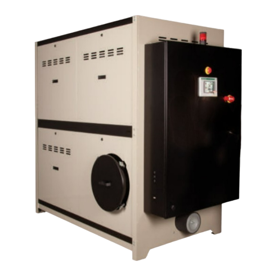
- Page 1 www.conairgroup.com U S E R G U I D E UGD043- Carousel Plus Dryer W Series Models 600 through 5000 with TouchView Technology (Siemens) Corporate Office: 724.584.5500 Instant Access 24/7 (Parts and Service): 800.458.1960 Parts and Service: 814.437.6861...
- Page 2 Firmware Version Number: Application File Name: DISCLAIMER: Conair shall not be liable for errors contained in this User Guide or for incidental, consequential damages in connection with the furnishing, performance or use of this information. Conair makes no warranty of any kind with regard to this information, including, but not limited to the implied warranties of merchantability and fitness for a particular purpose.
-
Page 3: Table Of Contents
Ta b l e o f C o n t e n t s I n t r o d u c t i o n Purpose of the user guide ....... 1-2 How the guide is organized . - Page 4 Opening the dryer doors ....... . 3-8 Connecting the air hoses to a single hopper ....3-9 Connecting the air hoses to ResinWorks .
- Page 5 Example set point change ......4-19 Control function descriptions ......4-25 Carousel Plus Dryer System security levels .
- Page 6 Passive alarms ........6-14 Dew point troubleshooting .
- Page 7 Ta b l e o f C o n t e n t s l...
- Page 8 l Ta b l e o f C o n t e n t s...
- Page 9 S E C T I O N I n t r o d u c t i o n P u r p o s e o f t h e u s e r g u i d e ....1 - 2 H o w t h e g u i d e i s o r g a n i z e d .
-
Page 10: I N T R O D U C T I O N
P u r p o s e o f t h e U s e r G u i d e This User Guide describes the Conair Carousel Plus Dryer with TouchView Technology (Siemens) and explains step-by-step how to install, operate, maintain and repair this equipment. -
Page 11: Using The Carousel Plus Dryer With Your System
U s i n g t h e C a r o u s e l P l u s D r y e r w i t h Yo u r S y s t e m The Conair Carousel Plus Dryer with TouchView Technology used within your... -
Page 12: At T E N T I O N
AT T E N T I O N : R e a d t h i s s o n o o n e g e t s h u r t We design equipment with the user’s safety in mind. You can avoid the potential hazards identified within this system by following the procedures outlined below and elsewhere in the User Guide. -
Page 13: Attention: Read This So No One Gets Hurt
AT T E N T I O N : R e a d t h i s s o n o o n e g e t s h u r t ( c o n t i n u e d ) We design equipment with the user’s safety in mind. -
Page 14: How To Use The Lockout Device
Lockout is the preferred method of isolating machines or equipment from energy sources. Your Conair product is equipped with the lockout device pictured below. To use the lockout device: Stop or turn off the equipment. -
Page 15: D E S C R I P T I O N
S E C T I O N D e s c r i p t i o n W h a t i s t h e C a r o u s e l P l u s D r y e r ? ..2 - 2 Ty p i c a l a p p l i c a t i o n s . -
Page 16: Typical Applications
W h a t i s t h e C a r o u s e l P l u s W S e r i e s D r y e r ? The Carousel Plus W Series Dryer with TouchView produces low-dew point air that removes moisture from hygroscopic plastics. - Page 17 Ty p i c a l A p p l i c a t i o n s ( c o n t i n u e d ) Model Drying Temperature Range Low temperature (with precooler)* 100° - 150°F {38° - 66°C} High heat (with aftercooler)* 150°...
- Page 18 H o w I t Wo r k s The Process (Drying) Cycle (W600 - 1000) Process air from the hopper is pulled into the dryer, through the process filter and then into the process blower inlet. Air exits the process blower and then enters the aftercooler, then passes through the desiccant wheel, where moisture is removed.
- Page 19 H o w I t Wo r k s ( c o n t i n u e d ) ( W 6 0 0 - W 1 6 0 0 , a n d W 3 2 0 0 ) ✐...
- Page 20 H o w I t Wo r k s ( c o n t i n u e d ) ( W 2 4 0 0 , W 4 0 0 0 a n d W 5 0 0 0 ) Power Purge W2400, 4000 and 5000 models have a Power Purge (cooling fan) feature integral to the desiccant wheel assembly.
-
Page 21: Specifications: Carousel Plus W Series
Maximum wire length between dryer and heat should be connected with the proper water flow rate and temperature to attain source is 100 feet {30 meters}. Consult Conair or a the optimal throughput. qualified electrician to determine gauge of wire required for distance. - Page 22 S p e c i f i c a t i o n s : C a r o u s e l P l u s W S e r i e s D e h u m i d i f y i n g D r y e r s ( c o n t i n u e d ) TPDX019-0713 MODELS...
- Page 23 †† Higher chilling water temperatures will require a greater flow rate. Specifications may change without notice. Consult a Conair sales representative for the most current information. 2 - 9 D e s c r i p t i o n l...
-
Page 24: Dryer Control Options
C a r o u s e l P l u s D r y e r C o n t r o l O p t i o n s • Visual alarms - The visible alarm is a blinking red alarm light that alerts the user to any shut down alarm. -
Page 25: I N S T A L L A T I O N
S E C T I O N I n s t a l l a t i o n Unpacking the boxes ......3-2 Preparing for installation . -
Page 26: Unpacking The Boxes
U n p a c k i n g t h e B o x e s The Carousel Plus W Series Dryer comes in one to four boxes, depending on the model and options ordered. The boxes could include (depending on the options selected): •... -
Page 27: Preparing For Installation
P r e p a r i n g f o r I n s t a l l a t i o n TIP: If you plan to ✒ use vacuum or com- pressed air loaders The Carousel Plus W Series Dryer is easy to install if you plan the location and prepare the to fill the hopper, mounting area properly. -
Page 28: Positioning The Dryer On The Floor
Po s i t i o n i n g t h e D r y e r o n t h e F l o o r Lift the dryer from the shipping container using a fork truck. Position the dryer on the floor near the hopper or ResinWorks sled. Make sure the location allows for the connection of all hoses, keeping hose lengths as short as possible. -
Page 29: Connecting The Delivery Air Rtd Probe
C o n n e c t i n g t h e D e l i v e r y A i r RT D P r o b e The delivery air RTD probe monitors the temperature of the drying air as it enters the hop- per. -
Page 30: Installing The Return Air Inlet And Air Outlet Adapters
I n s t a l l i n g t h e R e t u r n A i r I n l e t a n d A i r O u t l e t A d a p t e r s ( W 1 3 0 0 - 5 0 0 0 ) The Carousel Plus W Series Dryer’s return air inlet and air outlet adapters will be removed when the dryer is shipped... -
Page 31: Connecting The Main Power
NOTE: Wiring between process air heater, Heater Pack, and dryer where control for this heater is located is not included. Maximum working distance is 100 feet {30 meters}. Consult Conair or a qualified electrician to determine gauge of wire required for distance. -
Page 32: Opening The Dryer Doors
O p e n i n g t h e D r y e r D o o r s ( W 1 3 0 0 - 5 0 0 0 ) Carousel Plus W Series 600-5000 Dryers designed after December 2012 will have locking removable side panels. -
Page 33: Connecting The Air Hoses To A Single Hopper
C o n n e c t i n g t h e A i r H o s e s t o a S i n g l e H o p p e r ( W 1 3 0 0 - 5 0 0 0 ) Depending on how your dryer was configured, using the two flexible hoses or the hard piping kit provided, connect the inlet of the Heater Pack and outlet of the drying hopper to the dryer. -
Page 34: Connecting The Air Hoses To Resinworks
C o n n e c t i n g t h e A i r H o s e s t o a R e s i n Wo r k s Using the two flexible hoses provided, connect the delivery air and return air manifolds of the ResinWorks to the dryer. -
Page 35: Connecting The Dryer To The Hopper
NOTE: Because the W600 - 5000 models require a separate heat source for the delivery air, all references to this heat source will be identified as a Heater Pack, or a Conair “HTC” (Hopper Temperature Controller). When using this dryer with an HTC, reference the User Guide supplied with the HTC for installation instructions. -
Page 36: Connecting The Air Hose Adapters
C o n n e c t i n g A i r H o s e A d a p t e r s Depending on the hopper you purchased you may need to install an air hose adapter to con- ✐... -
Page 37: Optional Precooler
If a manual shut off valve is used, ✒ TIP: If an optional it should be mounted on the inlet flow control is also line. Conair recommends that both the being installed with supply and return water lines have a shut the aftercooler, the off valve. - Page 38 If a manual shut off valve is used, IMPORTANT: If an optional it should be mounted on the inlet flow control is also being line. Conair recommends that a installed with the aftercool- manual shut off valve be used on both er, the manual shut off the supply and return lines.
-
Page 39: Checking For Proper Air Flow
C h e c k i n g f o r P r o p e r A i r F l o w IMPORTANT: This procedure must be performed before loading material into the hopper. CAUTION: If the airflow direction is incorrect due to improper phase connection, material from the hopper can be pulled back into the dryer, causing permanent damage to this equipment. - Page 40 C h e c k i n g f o r P r o p e r A i r f l o w ( c o n t i n u e d ) Press the “Start” button and then the “Stop” button located within the Dryer: Dry Air Circuit window of the Dehumidifying Drying Screen.
- Page 41 C h e c k i n g f o r P r o p e r A i r f l o w ( c o n t i n u e d ) If airflow is incorrect, disconnect the power, follow proper lockout procedures and swap any 2 of the 3 incoming main power wires.
-
Page 42: Testing The Primary Receiver
Te s t i n g t h e P r i m a r y R e c e i v e r ( o p t i o n a l ) ✐ Make sure there is no material in the drying hopper. NOTE: Refer to loader manual for installation instructions. - Page 43 Te s t i n g t h e P r i m a r y R e c e i v e r ( o p t i o n a l ) ( c o n t i n u e d ) Press the “Enable”...
-
Page 44: Testing The Secondary Receiver
Te s t i n g t h e S e c o n d a r y R e c e i v e r ( o p t i o n a l ) Make sure there is no material in the drying hopper. Disconnect the material inlet hose of the optional receiver(s) at the source. - Page 45 Te s t i n g t h e S e c o n d a r y R e c e i v e r ( o p t i o n a l ) ( c o n t i n u e d ) Press the “Enable”...
-
Page 46: Testing The Installation
Te s t i n g t h e I n s t a l l a t i o n You have completed the installation. Now it’s time to make sure everything works. Check to ensure that there is no material in the drying hopper. If you have mounted an optional vacuum receiver on the hopper, disconnect the material inlet hose at the source. - Page 47 Te s t i n g t h e I n s t a l l a t i o n From the System Control Screen, press the “Start System” button. If everything is installed correctly: • The regeneration and process blowers turn on. •...
- Page 48 3 - 2 4 l I n s t a l l a t i o n - Te s t i n g...
-
Page 49: O P E R A T I O N
O p e r a t i o n S E C T I O N T h e C a r o u s e l P l u s D r y e r S y s t e m c o n t r o l p a n e l . - Page 50 D r y e r S y s t e m C o n t r o l Pa n e l On power-up, the Carousel Plus Dryer control displays the initial system "Login" screen. At start-up, the system security level is "Default". Once the operator enters the user name and password, access is permitted to the "Login Setup"...
-
Page 51: How To Navigate The Control Screens
H o w t o N a v i g a t e t h e C o n t r o l S c r e e n s Navigating through the Carousel Plus Dryer Control screens is intuitive due the touch screen in the control panel. - Page 52 H o w t o N a v i g a t e t h e C o n t r o l S c r e e n s ( c o n t i n u e d ) The user name, password and other information can be entered using the pop-up keyboard window that appears when an appropriate field is touched.
- Page 53 H o w t o N a v i g a t e t h e C o n t r o l S c r e e n s ( c o n t i n u e d ) When a system component is to be selected from a list of parameters, the “Drop down menus”...
-
Page 54: Control Function Flow Charts
C o n t r o l F u n c t i o n F l o w C h a r t s L o g i n F l o w C h a r t (continued) 4 - 6 l O p e r a t i o n... -
Page 55: Basic Controls
O p e r a t i o n - B a s i c C o n t r o l s 4 - 7 O p e r a t i o n l... -
Page 56: Operation Flow Chart 1
C o n t r o l F u n c t i o n F l o w C h a r t s ( c o n t i n u e d ) O p e r a t i o n F l o w C h a r t 1 (continued) 4 - 8 l O p e r a t i o n... -
Page 57: Operation Flow Chart 2
C o n t r o l F u n c t i o n F l o w C h a r t s ( c o n t i n u e d ) O p e r a t i o n F l o w C h a r t 2 (continued) 4 - 9 O p e r a t i o n l... - Page 58 4 - 1 0 l O p e r a t i o n...
-
Page 59: Dew Point Package Controls
O p e r a t i o n - D e w Po i n t Pa c k a g e C o n t r o l s O p e r a t i o n l 4 - 1 1... - Page 60 C o n t r o l F u n c t i o n F l o w C h a r t s ( c o n t i n u e d ) O p e r a t i o n F l o w C h a r t 1 4 - 1 2 l O p e r a t i o n...
- Page 61 C o n t r o l F u n c t i o n F l o w C h a r t s ( c o n t i n u e d ) O p e r a t i o n F l o w C h a r t 2 4 - 1 3 O p e r a t i o n l...
- Page 62 4 - 1 4 l O p e r a t i o n...
- Page 63 O p e r a t i o n - S e t u p C o n t r o l O p e r a t i o n l 4 - 1 5...
- Page 64 C o n t r o l F u n c t i o n F l o w C h a r t s ( c o n t i n u e d ) S e t u p F l o w C h a r t 1 (continued) 4 - 1 6 l O p e r a t i o n...
- Page 65 C o n t r o l F u n c t i o n F l o w C h a r t s ( c o n t i n u e d ) E q u i p m e n t S e t u p F l o w C h a r t 1 (continued) O p e r a t i o n l 4 - 1 7...
- Page 66 C o n t r o l F u n c t i o n F l o w C h a r t s ( c o n t i n u e d ) E q u i p m e n t S e t u p F l o w C h a r t 2 (continued) 4 - 1 8 l O p e r a t i o n...
-
Page 67: Example Set Point Change
C o n t r o l F u n c t i o n F l o w C h a r t s ( c o n t i n u e d ) E x a m p l e S e t Po i n t C h a n g e ✐... -
Page 68: Control Function Descriptions
C o n t r o l F u n c t i o n D e s c r i p t i o n s Login Screen ✐ NOTE: From the "Login" screen, a user can navigate through all of the Carousel Plus Dryer Control screens without logging onto the system. - Page 69 C o n t r o l F u n c t i o n D e s c r i p t i o n s ( c o n t i n u e d ) Press the "Enter" button to return to the "User/Password" window, after the user name or password has been entered.
- Page 70 C o n t r o l F u n c t i o n D e s c r i p t i o n s ( c o n t i n u e d ) System Overview Screen ✐...
- Page 71 C o n t r o l F u n c t i o n D e s c r i p t i o n s ( c o n t i n u e d ) Process Heater: Dehumidified Air Circuit Screen ✐...
- Page 72 C o n t r o l F u n c t i o n D e s c r i p t i o n s ( c o n t i n u e d ) Dehumidifying Dryer Screen ✐...
- Page 73 C o n t r o l F u n c t i o n D e s c r i p t i o n s ( c o n t i n u e d ) Primary Hopper Loader Screen (optional) ✐...
- Page 74 C o n t r o l F u n c t i o n D e s c r i p t i o n s ( c o n t i n u e d ) Dehumidifying Drying Screen ✐...
- Page 75 C o n t r o l F u n c t i o n D e s c r i p t i o n s ( c o n t i n u e d ) Alarm Log Screen To access the Alarm Log Screen: Press the "Alarm Log"...
- Page 76 C o n t r o l F u n c t i o n D e s c r i p t i o n s ( c o n t i n u e d ) System Control Screen ✐...
- Page 77 C o n t r o l F u n c t i o n D e s c r i p t i o n s ( c o n t i n u e d ) Auto Start Screen ✐...
- Page 78 C o n t r o l F u n c t i o n D e s c r i p t i o n s ( c o n t i n u e d ) Secondary Hopper Loader Screen (optional) ✐...
- Page 79 C o n t r o l F u n c t i o n D e s c r i p t i o n s ( c o n t i n u e d ) Main Setup Screen ✐...
- Page 80 C o n t r o l F u n c t i o n D e s c r i p t i o n s ( c o n t i n u e d ) Set Time Screen To access the Set Time Screen: Press the “Set Time &...
- Page 81 C o n t r o l F u n c t i o n D e s c r i p t i o n s ( c o n t i n u e d ) Equipment Setup Screen To access the Equipment Setup Screen: Press the "Equipment Setup"...
- Page 82 C o n t r o l F u n c t i o n D e s c r i p t i o n s ( c o n t i n u e d ) Dehumidified Air Circuit Setup Screen To access the Dehumidified Air Circuit Setup Screen: Press the "Dry Air Setup”...
- Page 83 C o n t r o l F u n c t i o n D e s c r i p t i o n s ( c o n t i n u e d ) Option Setup Screen To access the Option Setup Screen: Press the "Options”...
- Page 84 C o n t r o l F u n c t i o n D e s c r i p t i o n s ( c o n t i n u e d ) ✐ Instrument Setup 1 Screen NOTE: Set points boxes are white with heavy black borders.
- Page 85 C o n t r o l F u n c t i o n D e s c r i p t i o n s ( c o n t i n u e d ) Regeneration Heat PID Setup Screen ✐...
- Page 86 C o n t r o l F u n c t i o n D e s c r i p t i o n s ( c o n t i n u e d ) Instrument Setup 2 Screen ✐...
- Page 87 C o n t r o l F u n c t i o n D e s c r i p t i o n s ( c o n t i n u e d ) Primary Hopper Loader Setup Screen (optional) To access the Primary Hopper Loader Setup Screen: Press the "Loader”...
- Page 88 C o n t r o l F u n c t i o n D e s c r i p t i o n s ( c o n t i n u e d ) Secondary Hopper Loader Setup Screen (optional) To access the Secondary Hopper Loader Setup Screen: Press the "Loader”...
- Page 89 C o n t r o l F u n c t i o n D e s c r i p t i o n s ( c o n t i n u e d ) Exit Runtime To access the Exit Runtime Screen: Press the "Exit Runtime”...
- Page 90 C o n t r o l F u n c t i o n D e s c r i p t i o n s ( c o n t i n u e d ) Test Outputs Screen ✐...
- Page 91 C o n t r o l F u n c t i o n D e s c r i p t i o n s ( c o n t i n u e d ) ✐ NOTE: Set points boxes are Alarm Setup 1 Screen white with heavy black borders.
-
Page 92: Carousel Plus Dryer System Security Levels
(800) 458 1960 The Carousel Plus Dryer System is shipped with the password security level set at From outside of the "Supervisor". For information on how to change security levels, contact you Conair United States, call: Technical Service representative. (814) 437 6861 The following table and accompanying text gives an overview of the security levels and description of the functions available at each level. - Page 93 S t a r t i n g t h e D r y e r To start the dryer: Turn on the main power to the dryer and system components. Check to ensure that the all disconnect dials are in the "On" or “I” position. Fill the drying hopper with material by navigating the System Overview Screen and pressing the optional receiver's magnifying glass icon.
- Page 94 As the system is running, it will take several hours for all components to reach a steady-state running condition. Conair recom- mends waiting until the system is in a constant steady state before making any changes to temperature.
-
Page 95: Adjusting The Temperature Set Point
Any changes made to the set point temperature will affect the on time value ✐ NOTE: Making too large of a shown. To minimize energy usage, Conair recommends using the lowest set change in set point will point temperature that is required to dry your material and maintain the required change the material throat material throat temperature. -
Page 96: Using The Auto Start Timer
U s i n g t h e A u t o S t a r t Ti m e r You can set the dryer to start automatically using the Auto Start function. Supervisor Password is necessary to use this function. To use Auto Start: Navigate to the System Control screen, after logging in under the appro- priate user level. - Page 97 U s i n g t h e A u t o S t a r t Ti m e r ( c o n t i n u e d ) Enter the required dryer starting hour, minute, month, date and year by using the pop-up keypad window.
- Page 98 S t o p p i n g t h e C a r o u s e l P l u s D r y e r S y s t e m There are three (3) ways to stop the Carousel Plus Dryer with TouchView CAUTION: Improper Technology: shutdown can cause...
- Page 99 S t o p p i n g t h e C a r o u s e l P l u s D r y e r ✐ NOTE: If the operator presses S y s t e m ( c o n t i n u e d ) the “Stop System”...
- Page 100 U s i n g t h e L o a d i n g C o n t r o l F u n c t i o n ( o p t i o n a l ) The Carousel Plus Dryer’s TouchView Control can operate up to two optional receivers and vacuum pumps.
- Page 101 U s i n g t h e L o a d i n g C o n t r o l F u n c t i o n ( o p t i o n a l ) ( c o n t i n u e d ) Enter the required loader’s load time, dump time, purge time and alarm check settings by using the pop-up keypad window.
- Page 102 U s i n g t h e L o a d i n g C o n t r o l F u n c t i o n ( o p t i o n a l ) ( c o n t i n u e d ) S e c o n d a r y L o a d e r To adjust the optional secondary loader settings: Press the “Secondary Loader”...
- Page 103 U s i n g t h e L o a d i n g C o n t r o l F u n c t i o n ( o p t i o n a l ) ( c o n t i n u e d ) S e c o n d a r y L o a d e r Press the “Enabled”...
- Page 104 C o p y i n g F i l e s f r o m t h e C a r o u s e l P l u s D r y e r S y s t e m ✐...
-
Page 105: M A I N T E N A N C E
S E C T I O N M a i n t e n a n c e P r e v e n t a t i v e m a i n t e n a n c e c h e c k l i s t ..5 - 2 C h e c k i n g t h e d e w p o i n t . -
Page 106: Preventative Maintenance Checklist
P r e v e n t a t i v e M a i n t e n a n c e C h e c k l i s t Routine maintenance will ensure optimum operation and performance of the W Series Carousel Plus Dryer. - Page 107 P r e v e n t a t i v e M a i n t e n a n c e C h e c k l i s t ( c o n t i n u e d ) •...
-
Page 108: Checking The Dewpoint
C h e c k i n g t h e D e w p o i n t It is a good idea to monitor the dewpoint performance of your dryer periodically with a calibrated portable dewpoint monitor, to ensure it is performing at maximum capacity. -
Page 109: Cleaning The Hopper
C l e a n i n g t h e H o p p e r CAUTION: Hot surfaces. Always protect yourself from hot surfaces inside and out- side the dryer and drying hopper. IMPORTANT: The area inside the hopper is a confined The hopper, spreader cone, and discharge assembly should be cleaned thoroughly space. -
Page 110: Cleaning The Process Filter
If the filter has been used and cleaned sary. several times, it probably needs to be replaced with a new filter for optimum Conair’s Instant Access efficiency. 24/7 Parts and Service number is 800-458-1960. Outside the U.S., dial 814-437-6861. - Page 111 C l e a n i n g t h e P r o c e s s F i l t e r ( c o n t i n u e d ) C a r o u s e l P l u s W- s e r i e s D r y e r s 6 0 0 - 5 0 0 0 CAUTION: Hot surfaces.
-
Page 112: Cleaning The Regeneration Filter
Replace damaged, worn or clogged a new filter when neces- filters. sary. Reverse the procedure to reinstall the Conair’s Instant Access regeneration filter. Make sure that the 24/7 Parts and Service filter is completely seated in the filter number is housing. -
Page 113: Cleaning The Aftercooler Coils
C l e a n i n g t h e A f t e r c o o l e r C o i l s You need to clean the aftercooler coils to keep them working efficiently. Cleaning frequency depends on the type and amount of material you process. Stop the dryer and lockout the main power. -
Page 114: Draining The Volatile Drain
C l e a n i n g t h e A f t e r c o o l e r C o i l s ( c o n t i n u e d ) Clean the assembly using a mild soap and water. Let the assembly dry thoroughly before installation. -
Page 115: I N S P E C T I N G H O S E S A N D G A S K E T
I n s p e c t i n g H o s e s a n d G a s k e t s Loose or damaged hoses and gaskets can allow moisture to seep into the closed-loop drying system. Follow the hose routing of all the hoses within the dryer and inspect all hoses, clamps, fittings, and gaskets. -
Page 116: Cleaning The Precooler Coils
C l e a n i n g t h e P r e c o o l e r C o i l s You need to clean the precooler coils to keep them working efficiently. Cleaning frequency depends on the type and amount of material you process. Stop the dryer and lockout the main power. - Page 117 C l e a n i n g t h e Vo l a t i l e Tr a p o n t h e D e m i s t e r ( W 6 0 0 - 1 0 0 0 ) Stop the dryer and lockout the main power.
- Page 118 C l e a n i n g t h e Vo l a t i l e Tr a p o n t h e D e m i s t e r ( W 1 3 0 0 - 5 0 0 0 ) Stop the dryer and lockout the main power.
-
Page 119: Tr O U B L E S H O O T I N G
S E C T I O N Tr o u b l e s h o o t i n g B e f o r e b e g i n n i n g ....6 - 2 A f e w w o r d s o f c a u t i o n . -
Page 120: Before Beginning
B e f o r e B e g i n n i n g You can avoid most problems by following the recommended installation and maintenance procedures outlined in this User Guide. If you do have a problem, this section will help you determine what caused it and how to fix it. Before you open the side panels of the dryer be sure to: ❏... -
Page 121: A Few Words Of Caution
A Fe w Wo r d s o f C a u t i o n The Carousel Plus Dryer with TouchView Technology is equipped with numerous safety devices. Do not remove or disable them. Improper corrective action can lead to hazardous conditions and should never be attempted to sustain production. -
Page 122: How To Identify The Cause Of A Problem
H o w t o I d e n t i f y t h e C a u s e o f a P r o b l e m Most dryer malfunctions are indicated in the Status Box on the Control Panel screens. - Page 123 H o w t o I d e n t i f y t h e C a u s e o f a P r o b l e m ( c o n t i n u e d ) When an alarm message is displayed: Press the “Alarm Log”...
- Page 124 H o w t o I d e n t i f y t h e C a u s e o f a P r o b l e m ( c o n t i n u e d ) Find the error message in the diagnostics table of the following trou- bleshooting section or the troubleshooting section of the applicable component User Manual.
-
Page 125: Shutdown Alarms
S h u t d o w n A l a r m s If an alarm occurs, a red dialog box is displayed on the dryer’s touch screen control. The dryer will shut down automatically to prevent damage to the equipment or personnel. - Page 126 S h u t d o w n A l a r m s If an alarm occurs, a red dialog box is displayed on the dryer’s touch screen control. The dryer will shut down automatically to prevent damage to the equipment or personnel.
- Page 127 S h u t d o w n A l a r m s If an alarm occurs, a red dialog box is displayed on the dryer’s touch screen control. The dryer will shut down automatically to prevent damage to the equipment or personnel.
-
Page 128: Passive Alarm)
S h u t d o w n A l a r m s If an alarm occurs, a red dialog box is displayed on the dryer’s touch screen control. The dryer will shut down automatically to prevent damage to the equipment or personnel. - Page 129 S h u t d o w n A l a r m s If an alarm occurs, a red dialog box is displayed on the dryer’s touch screen control. The dryer will shut down automatically to prevent damage to the equipment or personnel.
- Page 130 S h u t d o w n A l a r m s If an alarm occurs, a red dialog box is displayed on the dryer’s touch screen control. The dryer will shut down automatically to prevent damage to the equipment or personnel.
- Page 131 S h u t d o w n A l a r m s If an alarm occurs, a red dialog box is displayed on the dryer’s touch screen control. The dryer will shut down automatically to prevent damage to the equipment or personnel.
-
Page 132: Passive Alarms
Pa s s i v e A l a r m s If an alarm occurs, a red dialog box is displayed on the dryer’s touch screen control. The dryer continues to operate, but this problem could prevent cor- rect drying of your material. The dialog box will indicate whether the alarm is a shut down alarm or a passive alarm. - Page 133 Pa s s i v e A l a r m s If an alarm occurs, a red dialog box is displayed on the dryer’s touch screen control. The dryer continues to operate, but this problem could prevent cor- rect drying of your material. The dialog box will indicate whether the alarm is a shut down alarm or a passive alarm.
- Page 134 Pa s s i v e A l a r m s If an alarm occurs, a red dialog box is displayed on the dryer’s touch screen control. The dryer continues to operate, but this problem could prevent cor- rect drying of your material. The dialog box will indicate whether the alarm is a shut down alarm or a passive alarm.
- Page 135 Pa s s i v e A l a r m s If an alarm occurs, a red dialog box is displayed on the dryer’s touch screen control. The dryer continues to operate, but this problem could prevent cor- rect drying of your material. The dialog box will indicate whether the alarm is a shut down alarm or a passive alarm.
- Page 136 Pa s s i v e A l a r m s If an alarm occurs, a red dialog box is displayed on the dryer’s touch screen control. The dryer continues to operate, but this problem could prevent cor- rect drying of your material. The dialog box will indicate whether the alarm is a shut down alarm or a passive alarm.
- Page 137 Pa s s i v e A l a r m s If an alarm occurs, a red dialog box is displayed on the dryer’s touch screen control. The dryer continues to operate, but this problem could prevent cor- rect drying of your material. The dialog box will indicate whether the alarm is a shut down alarm or a passive alarm.
- Page 138 Pa s s i v e A l a r m s If an alarm occurs, a red dialog box is displayed on the dryer’s touch screen control. The dryer continues to operate, but this problem could prevent cor- rect drying of your material. The dialog box will indicate whether the alarm is a shut down alarm or a passive alarm.
- Page 139 Pa s s i v e A l a r m s If an alarm occurs, a red dialog box is displayed on the dryer’s touch screen control. The dryer continues to operate, but this problem could prevent cor- rect drying of your material. The dialog box will indicate whether the alarm is a shut down alarm or a passive alarm.
-
Page 140: Dew Point Troubleshooting
Conair Parts at (800) 458 1960 for the addition of a volatile trap. Analog option board/sensor malfunction Verify dryer dew point readings with a calibrated portable dew point meter. -
Page 141: Poor Material Drying Troubleshooting
A majority of customer questions to Conair are related to dew point. It is important to realize that dew point is one of four requirements that need to be satisfied. - Page 142 Po o r M a t e r i a l D r y i n g Tr o u b l e s h o o t i n g ( c o n t i n u e d ) Once it is determined which of the four requirements that is not being satisfied, refer to the following list of possible causes and solutions.
- Page 143 Po o r M a t e r i a l D r y i n g Tr o u b l e s h o o t i n g ( c o n t i n u e d ) Residence Time - The time your material supplier has determined that the material in use must be heated to its drying temperature to achieve proper drying.
- Page 144 Po o r M a t e r i a l D r y i n g Tr o u b l e s h o o t i n g ( c o n t i n u e d ) Airflow - The airflow in the process drying circuit must be adequate to carry and distribute the heat throughout the entire bed of material inside the hopper.
- Page 145 -20 to -40° F {-29 to -40° C}. If your dryer does not United States, call: have a dew point readout, you can check the dew point with a portable dew point (814) 437 6861 instrument. Conair sells a variety of portable dew point meters. Contact Conair Parts. Problem Possible cause Solution Low regeneration temperature.
-
Page 146: Replacing Fuses
R e p l a c i n g F u s e s Disconnect and lockout the main power supply. Open the electrical enclosure door. Check the fuse with an ohmmeter. If necessary, pull the fuse out and replace it with a fuse of the same type and rating. -
Page 147: Checking Heater Solid State Relays
C h e c k i n g H e a t e r S o l i d S t a t e R e l a y s CAUTION: Always disconnect and lock out the main power sources before making electrical connections. - Page 148 C h e c k i n g o r R e p l a c i n g Te m p e r a t u r e S e n s o r s IMPORTANT : Always refer to the wiring diagrams that came with your dryer The Carousel Plus W Series Dryer uses RTD sensors to monitor the temperatures of the...
-
Page 149: Replacing The Regeneration Heater
R e p l a c i n g t h e R e g e n e r a t i o n H e a t e r ( W 6 0 0 - 1 0 0 0 ) Stop the dryer, disconnect the power, and follow prop- er lockout procedures. - Page 150 R e p l a c i n g t h e R e g e n e r a t i o n H e a t e r ( W 6 0 0 - 1 0 0 0 ) ( c o n t i n u e d ) Compare the markings on the outside of the regeneration heater tube to ensure the new one has the same voltage and kW ratings as the original heater tube.
- Page 151 R e p l a c i n g t h e R e g e n e r a t i o n H e a t e r ( W 1 3 0 0 - 2 4 0 0 ) Stop the dryer, disconnect and lockout the main power.
- Page 152 R e p l a c i n g t h e R e g e n e r a t i o n H e a t e r ( W 1 3 0 0 - 2 4 0 0 ) ( c o n t i n u e d ) Slide the original insulation over the new heater, or if the insulation was cut for removal, wrap the cut insulation sleeve around the new heater tube and secure it with heat tape.
- Page 153 R e p l a c i n g t h e R e g e n e r a t i o n H e a t e r ( W 3 2 0 0 - 5 0 0 0 ) Stop the dryer, disconnect and lockout the main power.
- Page 154 R e p l a c i n g t h e R e g e n e r a t i o n H e a t e r ( W 3 2 0 0 - 5 0 0 0 ) ( c o n t i n u e d ) Loosen the lower clamps that secure the tubing to the dryer bracket.
- Page 155 R e p l a c i n g t h e D e s i c c a n t W h e e l A s s e m b l y ( W 6 0 0 - 1 0 0 0 ) When desiccant becomes clogged or contaminated, you should replace the desiccant wheel to ensure optimum performance.
- Page 156 R e p l a c i n g t h e D e s i c c a n t W h e e l A s s e m b l y ( W 6 0 0 - 1 0 0 0 ) ( c o n t i n u e d ) Lift the new desiccant wheel into the dryer frame, being sure it is oriented properly.
- Page 157 R e p l a c i n g t h e D e s i c c a n t W h e e l A s s e m b l y ( W 1 3 0 0 - 5 0 0 0 ) If you need to service the desiccant wheel assembly (wheel, motor, belts, etc.), use the fol- lowing procedure to remove the entire assembly from the dryer.
- Page 158 R e p l a c i n g t h e D e s i c c a n t W h e e l ( W 1 3 0 0 - 5 0 0 0 ) When desiccant becomes clogged or contaminated, you should replace the desiccant wheel to ensure optimum performance.
- Page 159 R e p l a c i n g t h e D e s i c c a n t W h e e l ( W 1 3 0 0 - 5 0 0 0 ) ( c o n t i n u e d ) On the motor side of the wheel assembly, while noting the number of turns, relieve the tension on the drive bolt by loosening the nut above the tension spring until the belt can be slipped off the motor sprocket.
- Page 160 R e p l a c i n g t h e D e s i c c a n t W h e e l ( W 1 3 0 0 - 5 0 0 0 ) ( c o n t i n u e d ) Place the belt on your new wheel unless you are replacing the belt at the same time, in which case you should put the new belt on the new wheel.
-
Page 161: Replacing The Desiccant Wheel Motor
R e p l a c i n g t h e D e s i c c a n t W h e e l M o t o r ( W 6 0 0 - 1 0 0 0 ) Stop the dryer, disconnect and lockout the main power. - Page 162 R e p l a c i n g t h e D e s i c c a n t W h e e l M o t o r ( W 1 3 0 0 - 5 0 0 0 ) Stop the dryer, disconnect and lockout the main power.
- Page 163 R e p l a c i n g t h e D e s i c c a n t W h e e l M o t o r ( W 1 3 0 0 - 5 0 0 0 ) ( c o n t i n u e d ) Slip the belt onto the sprocket, and adjust the tension spring nut to its original position.
- Page 164 6 - 4 6 l Tr o u b l e s h o o t i n g...
-
Page 165: Appendix
Conair equipment may be ordered through the Customer Conair has made the largest investment in customer support in the plastics indus- Service or Parts Department for a try. Our service experts are available to help with any problem you might have nominal fee. -
Page 166: Equipment Guarantee
(except for parts that are typically replaced after normal usage, such as filters, liner plates, etc.). Conair’s guarantee is limited to replacing, at our option, the part or parts determined by us to be defective after examination. The customer assumes the cost of transportation of the part or parts to and from the factory. - Page 167 W h a t i s t h e C o n a i r H a r d P i p i n g K i t ? Conair’s Hard Piping Kit is for use with your drying system. Conair recom- mends the hard pipe kit for line sizes of eight inches and larger.
- Page 168 ❒ Two (2) welded slip tube, 12 inch x 8 inch, coated CS, 19 GA (PN 2561330701) ❒ Six (6) 12 inch slip tube ring seal (PN 26713203) ❒ Six (6) 12 inch Conair flange to 12 inch adapter (PN 18477902) ❒ Twenty-nine (29) 12 inch bolted pull ring, galvanized (PN 2671350301) ❒...
- Page 169 ❒ One (1) welded slip tube, 12 inch x 8 inch, coated CS, 19 GA (PN 2561330701) ❒ Three (3) 12 inch slip tube ring seal (PN 26713203) ❒ One (1) 12 inch Conair flange to 12 inch adapter (PN 18477902) ❒ Nine (9) 12 inch bolted pull ring, galvanized (PN 2671350301) ❒...
- Page 170 Your plant layout and drying system component positioning will determine the organization of pieces necessary to complete the piping between the dryer and hopper. Each application will vary. Conair recommends that you take the following steps before starting installation. Organize all like pieces.
- Page 171 U s i n g P u l l R i n g C o n n e c t i o n s The following are general usage instructions for pull-ring connections with U-shaped seals. This is the primary style of connection used with Conair hard pipe kits. Pull the U-shaped seal around one of the pipe flanges. The seal can be stretched to fit, but avoid overstretching.
- Page 172 Slide the standard tube into the slip tube to the desired length. To order a slip tube or other parts for your hard pipe kit, Conair’s Instant Access 24/7 Parts and Service ✐ Air Flow Direction number is NOTE: The slip tube overlap must be at least 800-458-1960.
- Page 173 Your hard pipe kit a Conair flange adapter. This adapter must be attached to the dryer prior to assembling the rest of the hard pipe system. If adding the hard pipe kit to an existing drying system, remove the flexible hose from the dryer inlet and outlet.
- Page 174 90° bend to continue horizontally. A slip tube may need to be used as part of the last section hard pipe kit, Conair’s before the turn to horizontal to fit your plant/system layout. Refer to Using Slip Tubes earli-...
- Page 175 O p t i o n a l V F D Ve l o c i t y M e t e r t u b i n g ( r e q u i r e d f o r V F D o p e r a t i o n ) The velocity meter requires a special section of hard pipe, with a tapped fitting location for the velocity meter installation.
- Page 176 P r o p e r L o c a t i o n a n d u s e o f H a n g e r, C l a m p, a n d A l l - t h r e a d Your Conair Hard Pipe Kit comes with a quantity of tubing hangers (varies depending on Channel or other structural support as reqd.
Need help?
Do you have a question about the Carousel Plus UGD043-1216 and is the answer not in the manual?
Questions and answers