Table of Contents
Advertisement
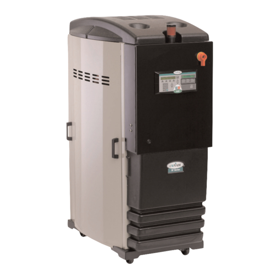
U S E R G U I D E
UGD025-0407
Carousel Plus Dryer
W Series Models 150, 200, 300 and 400 with DC-2 Controls
INTRODUCTION
•
Purpose of the User Guide
Read this so no one gets hurt
applications
•
How it works
lation
•
Mounting the dryer and hopper on a Processing Machine
per on the throat
•
Mounting the dryer on the floor stand; Hopper on the throat
mobile floor stand
•
Connecting the main power
air hose adapters
•
Connecting water hoses
loader on the hopper
•
OPERATION
Function Description
• To
start drying
Corporate Office: 412.312.6000
•
How the guide is organized
•
How to use the lockout device
•
Specifications: W Dryer
•
•
Checking for proper air flow
•
Connecting the RTD probe
•
How it works
•
The W dryer control panel
•
To stop drying
•
l
Instant Access 24/7 (Parts and Service): 800.458.1960
•
Your responsibilities as a user
•
DESCRIPTION
•
INSTALLATION
•
Unpacking the boxes
•
Positioning the dryer on the floor; Mounting the hop-
•
Mounting the dryer and hopper on the
•
Connecting the air hose
•
Connecting the setback RTD
•
Using the auto start timer
l
www.conairnet.com
•
ATTENTION:
What is the W Dryer?
•
•
Preparing for instal-
•
Connecting
•
Mounting a
W dryer control functions
•
Parts and Service: 814.437.6861
Typical
Control
Advertisement
Chapters
Table of Contents

Related Manuals for Conair 150


Summary of Contents for Conair 150
- Page 1 U S E R G U I D E UGD025-0407 Carousel Plus Dryer W Series Models 150, 200, 300 and 400 with DC-2 Controls INTRODUCTION • Purpose of the User Guide • How the guide is organized • Your responsibilities as a user •...
- Page 2 * NOTE: Displayed upon initialization, during power up, or on a data tag inside the door. DISCLAIMER: The Conair Group, Inc., shall not be liable for errors contained in this User Guide or for incidental, consequential damages in connection with the furnishing, performance or use of this information.
-
Page 3: Table Of Contents
Ta b l e o f C o n t e n t s I n t r o d u c t i o n Purpose of the user guide ....... . 1-2 How the guide is organized . - Page 4 Connecting the aftercooler ......3-13 Mounting a loader on the hopper ......3-14 Testing the installation .
- Page 5 Tr o u b l e s h o o t i n g Before beginning........6-2 A few words of caution .
- Page 6 A p p e n d i x Cleaning the aftercooler and precooler coils ....C-1 A p p e n d i x C l e a n i n g t h e Vo l a t i l e Tr a p o n t h e D e m i s t e r .
- Page 7 S E C T I O N I n t r o d u c t i o n P u r p o s e o f t h e u s e r g u i d e ....1 - 2 H o w t h e g u i d e i s o r g a n i z e d .
-
Page 8: I N T R O D U C T I O N
P u r p o s e o f t h e U s e r G u i d e This User Guide describes the Conair Carousel Plus W Series Dryers and explains step-by-step how to install, operate, maintain, and repair this equipment. -
Page 9: Using The Carousel Plus W Series As A Central Dryer
U s i n g t h e C a r o u s e l P l u s W S e r i e s a s a C e n t r a l D r y e r This manual incorporates the information necessary to use the Conair Carousel Plus W series dryer as a central dryer. Throughout this manual, information particular to central dyer application of the W series dryer is called out by the following treatment. -
Page 10: At T E N T I O N
AT T E N T I O N : R e a d t h i s s o n o o n e g e t s h u r t We design equipment with the user’s safety in mind. You can avoid the potential hazards identified on this machine by following the procedures outlined below and elsewhere in the User Guide. -
Page 11: Attention: Read This So No One Gets Hurt
AT T E N T I O N : R e a d t h i s s o n o o n e g e t s h u r t ( c o n t i n u e d ) We design equipment with the user’s safety in mind. -
Page 12: How To Use The Lockout Device
Lockout is the preferred method of isolating machines or equipment from energy sources. Your Conair product is equipped with the lockout device pictured below. To use the lockout device: Stop or turn off the equipment. -
Page 13: D E S C R I P T I O N
S E C T I O N D e s c r i p t i o n W h a t i s t h e C a r o u s e l P l u s W S e r i e s D r y e r ? . . 2 - 2 Ty p i c a l a p p l i c a t i o n s . -
Page 14: Typical Applications
Dryer on the floor; hopper on the throat. Hopper on a floor stand; the dryer next to it. Dryer and hopper on a mobile floor stand (MDC version 150 and 200 only). Central dryer, with ResinWorks system. The W Series Dryer can be used successfully in applications that require: •... - Page 15 * See page 3-13 and Appendix B and C. When supplied for central drying appli- • Throughput rates of 150 to 400 lbs {68.1 to 149.2 kg} per hour (some cations, the W series materials can be run at a higher rate). dryer is not equipped •...
-
Page 16: How It Works
H o w I t Wo r k s The W dryer achieves continuous, closed loop drying by passing air simultaneous- ly through two heaters and a continuously rotating desiccant wheel. ROCESS RYING YCLE The process blower pulls moist air from the top of the drying hopper. The air passes through the process filter and aftercooler into the desiccant wheel, where moisture is removed. - Page 17 H o w I t Wo r k s ( c o n t i n u e d ) ALARM LIGHT PROCESS PROCESS PROTECTION ALARM BELL REGENERATION PROCESS BLOWER HEATER BOX HIGH TEMP SHUTOFF REGENERATION AIR FILTER HIGH TEMP SHUTOFF REGENERATION HEATER...
-
Page 18: Specifications: Carousel Plus W Series Dryer
† Dryers running at 50 HZ will have 17% less airflow, and a 17% reduction in material throughput. Specifications may change without notice. Consult a Conair representative for the most current information. TPDS018-0705-REV 2 - 6 l D e s c r i p t i o n... -
Page 19: Carousel Plus W Series Dryer Options
C a r o u s e l P l u s W S e r i e s D r y e r O p t i o n s • Volatile trap (only in conjunction with aftercooler) - The volatile trap is recommended if drying materials that produce volitales that condense into a waxy or oily residue and/or if the material contains excessive fines. - Page 20 2 - 8 l D e s c r i p t i o n...
-
Page 21: I N S T A L L A T I O N
S E C T I O N I n s t a l l a t i o n U n p a c k i n g t h e b o x e s ....3 - 2 P r e p a r i n g f o r i n s t a l l a t i o n . -
Page 22: Unpacking The Boxes
U n p a c k i n g t h e B o x e s The Carousel Plus W series dryer comes in one to four boxes, depending on the model and options ordered. The boxes could include (depending on the options selected): •... - Page 23 Central dryer, with ResinWorks system. ✐ NOTE: Conair also sells an MDC (dryer and hopper on a mobile floor stand with convey- ing capabilities) version of this dryer in the 150 and 200 Models. Contact Conair Sales for additional information.
-
Page 24: Preparing For Installation
P r e p a r i n g f o r I n s t a l l a t i o n The Carousel Plus W Series Dryer is easy to install if you plan the location and prepare the mounting area properly. -
Page 25: Positioning The Dryer On The Floor
Po s i t i o n i n g t h e D r y e r o n t h e F l o o r Lift the dryer from the shipping container using a fork truck. Position the dryer on the floor near the processing machine. Make sure the location allows for the connection of all hoses. -
Page 26: Connecting The Main Power
C o n n e c t i n g t h e M a i n Po w e r CAUTION: Always disconnect and lock out the main power sources before making electrical connections. Electrical connections should be made only by qualified personnel. Open the dryer’s electrical enclosure. -
Page 27: C O N N E C T I N G T H E P R O C E S S Rt D P R O B E
C o n n e c t i n g t h e P r o c e s s RT D P r o b e The process RTD probe monitors the temperature of the drying air as it enters the hopper. -
Page 28: Checking For Proper Air Flow
C h e c k i n g f o r P r o p e r A i r F l o w This procedure is needed on W 150 - 400 models if the phase detection option was not ordered with the dryer. - Page 29 C h e c k i n g f o r P r o p e r A i r F l o w ( c o n t i n u e d ) Press the START button. Hold your hand near the delivery air Start outlet.
- Page 30 ( c o n t i n u e d ) ✐ INSTALLATION NOTE: Models 150, 200, 300, and 400 These models use a three-phase process blower. If the dryer shuts down and a Process Loop Break shutdown alarm is indicated within the first few minutes of operation, check for proper air flow or check the Process RTD for proper installation.
-
Page 31: Connecting The Air Hoses
✐ NOTE: Water to cooler W 150 has a 2 1/2 inch {63.5 mm} inlet and outlet hose connections. should be turned off W 200, W 300 and W 400 have a 5 inch {127 mm} inlet and outlet hose connec- when the dryer is not tions. -
Page 32: Connecting Air Hose Adapters
C o n n e c t i n g A i r H o s e A d a p t e r s Depending on the hopper you purchased you may need to install an air hose adapter to connect the hopper to your dryer. To connect the air hose adapter: Place high temperature gasket half way down over the dryer outlet to the hopper. -
Page 33: Connecting The Aftercooler
C o n n e c t i n g t h e A f t e r c o o l e r ( O p t i o n a l ) The aftercooler and optional precooler require a source of city, tower, or chiller water and a discharge or return line. -
Page 34: Mounting A Loader On The Hopper
Set the drying temperatures. Press temperature select with the select category button, and then press the Setpoint Adjust (+) or (-) buttons or enter the low setpoint temperature (150ºF {66ºC}) on the numeric keypad and press enter. When configured... - Page 35 • The blowers will continue running as needed to cool the heaters (until both heaters are less than 150°F {66ºC}) or ten minutes, whichever is shorter. The test is over. If the dryer performed the normal operating sequences as out- lined, you can load the hopper and begin operation.
-
Page 36: U S I N G C O M M U N I C A T I O N S
U s i n g C o m m u n i c a t i o n s ( O p t i o n a l ) To use the optional Modbus, Ethernet, SPI or standard DeviceNet communica- tions, see the Addendum for hardware installation and configuration. - Page 37 S E C T I O N O p e r a t i o n C a r o u s e l P l u s W s e r i e s d r y e r : c o n t r o l p a n e l D C - 2 .
- Page 38 C a r o u s e l P l u s W S e r i e s D r y e r : C o n t r o l Pa n e l D C - 2 M e n u B u t t o n S c r o l l B u t t o n s Press to scroll through the closed loop parameter...
-
Page 39: Control Function Flow Charts
C a r o u s e l P l u s W S e r i e s D r y e r C o n t r o l F u n c t i o n s Dryer functions are values that you can set or monitor in the Screen Title and Status Display windows. - Page 40 ACT -47˚F SET -40˚F MACHINE LOADER MACHINE LOADER DM T6 TOP MACHINE LOADER LOAD TIME 10 SEC LOAD TIME 10 SEC ACT 150˚F LOAD TIME 10 SEC HOPPER LOADER DM T5 PRESS HOPPER LDR VIRGIN LOAD TIME 10 SEC PRESS ACT 155˚F...
- Page 41 PANEL INSIDE TEMP TOTAL POWER ACT 100˚F 80 KWH RUNNING MACHINE LOADER DM T6 TOP PROCESS DEWPOINT LOAD TIME 10 SEC ACT 150˚F ACT -47 ˚F SET -100˚F HOPPER LOADER DM T5 PROCESS DEWPOINT LOAD TIME 10 SEC ACT 155˚F AVERAGE -55 ˚F...
- Page 42 SCREEN # DRYER MAIN MENU STAT SETUP DIAG DRYER SETUP PROC ALM DISP OTHER SETUP PROCESS PROC REGN OTHER CENTRAL DRYER STANDARD DRYER AND MDC SETUP PROCESS SETUP PROCESS PROC RETPID PROC PROPID RETPID SETUP PROCESS SETUP PROCESS HEATER SETUP AFTERCOOLER SETUP AFTERCOOLER SETUP PROCESS on off VALUE SCREENS...
- Page 43 WEDNESDAY START TIME REGEN CALIBRATION 8:00 REGEN DERIVATIVE OFFSET 0˚F WEDNESDAY STOP TIME PROCESS DEWPOINT 6:00 REGEN PID RESET SAMPLE RATE 150 SEC HEAT THURSDAY START TIME PROCESS DEWPOINT REGEN CALIBRATION 8:00 TRIM UP LIMIT 375˚F OFFSET 0˚F THURSDAY STOP TIME...
- Page 44 DRYER MAIN MENU STAT SETUP DIAG DRYER SETUP PROC ALM DISP OTHER ALARM ALARM DRYER SETUP CONTROL ACTION SETUP DISPLAY SCREENS UNITS STANDARD EDIT DRYER SETUP ALARM DRYER SETUP ALARM METRIC ACTION SCREENS SETPOINT SCREENS TIME DISPLAY PROC TEMP DEVIATION PROCESS HIGH TEMP 12 HOUR 385˚F...
- Page 45 DRYER MAIN MENU STAT SETUP DIAG DRYER SETUP PROC ALM DISP OTHER DRYER SETUP OTHER OPT INSP COM PW Logging Out Dryer Setup DRYER SETUP OPTIONS DRYER SETUP MODEL DRYER SETUP Password … Password Screen INFORMATION SCREENS CONFIG SCREENS COMMUNICATIONS IF A VALID PASSWORD IS STILL ACTIVE SETBACK ON TEMP MODEL NUMBER...
- Page 46 When configured as a central dryer, there is no process heater in the system. Therefore, any function associated with the process heater is not available for central dryer configurations. 4 - 1 0 l O p e r a t i o n...
-
Page 47: Control Function Descriptions
Once power is turned on, this screen is SCREEN 1 displayed for 3 seconds. It shows under screen 85 on page CONAIR D100 CONAIR and the dryer type on the first 4-32. CV2.21.00 DV2.21.00 line, and the control program version and display program version on the second line. - Page 48 C o n t r o l F u n c t i o n D e s c r i p t i o n s ( c o n t i n u e d ) F u n c t i o n S c r e e n SCREEN 3 (Default Screen) SETUP, PROC, PROC, PROC, PROCESS...
- Page 49 These control screens are not used for the SCREENS 7, 8, 9, and 10 W 150-400 DC-2. SCREEN 11 (Dewpoint Control This screen will show the actual dewpoint and/or Dewpoint Monitor)
- Page 50 C o n t r o l F u n c t i o n D e s c r i p t i o n s ( c o n t i n u e d ) F u n c t i o n S c r e e n This is the Dryer Status screen.
- Page 51 C o n t r o l F u n c t i o n D e s c r i p t i o n s ( c o n t i n u e d ) F u n c t i o n S c r e e n The screen shows the process protection SCREEN 16...
- Page 52 C o n t r o l F u n c t i o n D e s c r i p t i o n s ( c o n t i n u e d ) F u n c t i o n S c r e e n SCREEN 21 B (Aftercooler Flow This screen shows if the control is opening...
- Page 53 C o n t r o l F u n c t i o n D e s c r i p t i o n s ( c o n t i n u e d ) F u n c t i o n S c r e e n This screen displays the average dewpoint SCREEN 24 (Dewpoint Control...
- Page 54 C o n t r o l F u n c t i o n D e s c r i p t i o n s ( c o n t i n u e d ) F u n c t i o n S c r e e n SCREEN 27 This screen shows the actual temperature...
- Page 55 C o n t r o l F u n c t i o n D e s c r i p t i o n s ( c o n t i n u e d ) F u n c t i o n S c r e e n ✒...
- Page 56 OTHER Setup (screen 36). By pressing the Select ✐ Category buttons under the titles, the user NOTE: Conair is not responsi- can select to see setup information for ble for damage caused by Process, Regeneration, or Other. excessively high drying...
- Page 57 C o n t r o l F u n c t i o n D e s c r i p t i o n s ( c o n t i n u e d ) F u n c t i o n S c r e e n Before performing an autotune, set the set- SCREEN 40...
- Page 58 NOTE: Screens 49, 50, 51, PROCESS DEWPOINT after making a change. This time value 52, 53 and 54 apply to SAMPLE RATE 150 SEC gives the system time to respond to a the dewpoint control process change. option. 4 - 2 2...
- Page 59 C o n t r o l F u n c t i o n D e s c r i p t i o n s ( c o n t i n u e d ) F u n c t i o n S c r e e n ✐...
- Page 60 C o n t r o l F u n c t i o n D e s c r i p t i o n s ( c o n t i n u e d ) F u n c t i o n S c r e e n SCREEN 56 This is the auto start screen for the first...
- Page 61 C o n t r o l F u n c t i o n D e s c r i p t i o n s ( c o n t i n u e d ) F u n c t i o n S c r e e n This is the alarm action and setup screen.
- Page 62 This screen shows the return air tempera- tures at which the dryer will give a passive RETURN AIR ALARMS alarm, and when the dryer will shutdown PASS 150°F SHUT 180°F on High Return Air Temperature. 4 - 2 6 l O p e r a t i o n...
- Page 63 C o n t r o l F u n c t i o n D e s c r i p t i o n s ( c o n t i n u e d ) S c r e e n F u n c t i o n This screen shows the low CFM setpoint.
- Page 64 C o n t r o l F u n c t i o n D e s c r i p t i o n s ( c o n t i n u e d ) F u n c t i o n S c r e e n SCREEN 70 This is the amount of time from start-up...
- Page 65 Once an option is installed, there may be additional screens that show in the menu structure that need to be setup. Contact Conair Service to determine what options should be installed on your dryer. This screen is used with the current moni-...
- Page 66 C o n t r o l F u n c t i o n D e s c r i p t i o n s ( c o n t i n u e d ) F u n c t i o n S c r e e n SCREEN 78 This screen further defines the dryer type...
- Page 67 C o n t r o l F u n c t i o n D e s c r i p t i o n s ( c o n t i n u e d ) F u n c t i o n S c r e e n This screen shows the communications protocol.
- Page 68 C o n t r o l F u n c t i o n D e s c r i p t i o n s ( c o n t i n u e d ) F u n c t i o n S c r e e n This screen shows the password entry SCREEN 85...
- Page 69 C o n t r o l F u n c t i o n D e s c r i p t i o n s ( c o n t i n u e d ) F u n c t i o n S c r e e n SCREEN 88 This is the password logout screen.
- Page 70 C o n t r o l F u n c t i o n D e s c r i p t i o n s ( c o n t i n u e d ) F u n c t i o n S c r e e n SCREEN 92 This is an example of one of the alarm his-...
- Page 71 C o n t r o l F u n c t i o n D e s c r i p t i o n s ( c o n t i n u e d ) F u n c t i o n S c r e e n This is the Diagnostic I/O screen.
- Page 72 These values should not be changed except under the direction of Conair Engineering or Service. 4 - 3 6 l O p e r a t i o n...
-
Page 73: To Start Drying
To S t a r t D r y i n g Make sure there is material in the hopper. Turn on the main power to the dryer Make sure the dryer’s disconnect dial is in the ON position. This powers up the control and the display lights will illu- minate. -
Page 74: To Stop Drying
To S t a r t D r y i n g ( c o n t i n u e d ) Press the START button. Start If everything is installed correctly: • The green light on the start button will illuminate. •... -
Page 75: How To Use The Supervisor's Password
H o w t o U s e t h e S u p e r v i s o r ’s Pa s s w o r d The supervisor's password must be entered before you can use or make changes to some screens on the dryer control. - Page 76 H o w t o U s e t h e S u p e r v i s o r ’s Pa s s w o r d ( c o n t i n u e d ) This is the screen where you will need to enter the supervisor's password.
-
Page 77: Using The Auto Start Timer
U s i n g t h e A u t o S t a r t Ti m e r You can set the dryer to start and stop automatically using the Auto Start and ✐ Auto Stop functions. Supervisor Password is necessary to use this function. NOTE: To use the Auto Start or Auto Stop Timer, P r o g r a m m i n g A u t o S t a r t... - Page 78 ° F {66 ° C} due NOTE: Conair is not responsible for damage caused by excessively high drying set- to nuisance alarms. points that are not in accordance with your drying material recommendations. 4 - 4 2 l O p e r a t i o n...
-
Page 79: Using Dewpoint Control
U s i n g D e w p o i n t C o n t r o l Your dryer is equipped with a dewpoint monitor and dewpoint control features. You can choose to use it as a monitor only device, or to maintain a steady dewpoint that you select with the dewpoint control. - Page 80 U s i n g t h e S e t b a c k Fe a t u r e The DC-2 comes standard with setback installed, but disabled. You can choose to set the mode to "Off", "Temperature", or "Manual On". Refer to the Control Function Descriptions later in this section for more detailed information.
-
Page 81: Setback Feature Guidelines
Setback Temp Drying Temp Screen #27 (Process) Screen #26 160° F {71° C} 120° F {49° C} 150° F {66° C} 240° F {116° C} 135° F {57° C} 180° F {82° C} 300° F {149° C} 160° F {71° C} 200°... - Page 82 The “Setback Temperature (Process)” should not be set lower than 150° F {66° C}, even if the control will allow it. It is very likely the dryer will not be able to achieve low temperatures without adding additional cooling to the process air circuit.
-
Page 83: M A I N T E N A N C E
S E C T I O N M a i n t e n a n c e P r e v e n t a t i v e m a i n t e n a n c e c h e c k l i s t ..5 - 2 C h e c k i n g t h e d e w p o i n t . - Page 84 P r e v e n t a t i v e M a i n t e n a n c e C h e c k l i s t Routine maintenance will ensure optimum operation and performance of the W Dryer.
- Page 85 Even if your dryer has a dewpoint readout, comparing it to a ✐ NOTE: Portable dewpoint moni- portable instrument periodically will confirm that the dewpoint sensor and readout tors purchased from Conair are is performing properly. provided with a male connector that plugs into the Dewpoint To check dewpoint: Check port.
- Page 86 C h e c k i n g t h e D e w p o i n t ( c o n t i n u e d ) Turn on the portable instrument, and ensure there is positive airflow through the sensor.
-
Page 87: Cleaning The Hopper
C l e a n i n g t h e H o p p e r ( 1 5 0 - 2 0 0 ) CAUTION: Hot surfaces. Always protect yourself from hot surfaces inside and out- side the dryer and drying hopper. The hopper, spreader cone, and discharge assembly should be cleaned thoroughly between material changes to prevent resin contamination. -
Page 88: Cleaning The Process Filter
C l e a n i n g t h e P r o c e s s F i l t e r Clogged filters reduce air flow and dryer efficiency. Cleaning frequency depends on how much material you process and how dusty or full of fines it is. Push in on the sides to release the tabs on the front cover. - Page 89 C l e a n i n g t h e P r o c e s s F i l t e r ( c o n t i n u e d ) Remove outer filter and clean it with soapy water. Let air dry.
-
Page 90: Cleaning The Regeneration Filter
C l e a n i n g t h e R e g e n e r a t i o n F i l t e r Clogged filters reduce air flow and dryer efficiency. Cleaning frequency depends on how much material you process and how dusty or full of fines it is. - Page 91 C l e a n i n g t h e R e g e n e r a t i o n F i l t e r ( c o n t i n u e d ) Clean dust, fines, and dirt from the filter, or replace it with a new filter.
-
Page 92: Cleaning The Aftercooler Coils
C l e a n i n g t h e A f t e r c o o l e r C o i l s The aftercooler coils will need to be kept clean to keep the aftercooler working efficiently. - Page 93 C l e a n i n g t h e A f t e r c o o l e r C o i l s Clean the assembly using a mild soap and water. Let the assembly dry thoroughly before installation. In severe situations, steam cleaning or use of solvents maybe necessary.
-
Page 94: Cleaning The Precooler Coils
C l e a n i n g t h e P r e c o o l e r C o i l s If you have the optional precooler, you need to clean the cooling coils to keep them working efficiently. - Page 95 S E C T I O N Tr o u b l e s h o o t i n g B e f o r e b e g i n n i n g ....6 - 2 A f e w w o r d s o f c a u t i o n .
-
Page 96: Tr O U B L E S H O O T I N G
B e f o r e B e g i n n i n g ✐ You can avoid most problems by following the recommended installation and NOTE: Use of test maintenance procedures outlined in this User Guide. If you do have a problem, mode screens 28-43 this section will help you determine what caused it and how to fix it. -
Page 97: A Few Words Of Caution
B e f o r e B e g i n n i n g ( c o n t i n u e d ) ❏ Find the wiring and equipment diagrams that were shipped with your dryer. These diagrams are the best reference for correct- ing a problem. - Page 98 H o w t o I d e n t i f y t h e C a u s e o f a P r o b l e m ✐ NOTE: Pushing the Dryer alarms are indicated by an illuminated Acknowledge Alarm light on the W Acknowledge Alarm button series dryer control panel.
-
Page 99: Shut Down Alarms
S h u t d o w n A l a r m s If the red Acknowledge Alarm LED is blinking, the alarm is a shutdown alarm. The dryer will shutdown automatically to prevent damage to the When supplied for central equipment or personnel. - Page 100 S h u t d o w n A l a r m s If the red Acknowledge Alarm LED is blinking, the alarm is a shutdown alarm. The dryer will shutdown automatically to prevent damage to the When supplied for central equipment or personnel.
- Page 101 S h u t d o w n A l a r m s If the red Acknowledge Alarm LED is blinking, the alarm is a shutdown alarm. The dryer will shutdown automatically to prevent damage to the equipment or personnel. Note that once the Acknowledge Alarm button is pressed once, the blinking red LED becomes solid.
- Page 102 S h u t d o w n A l a r m s If the red Acknowledge Alarm LED is blinking, the alarm is a shutdown alarm. The dryer will shutdown automatically to prevent damage to the When supplied for central equipment or personnel.
- Page 103 S h u t d o w n A l a r m s If the red Acknowledge Alarm LED is blinking, the alarm is a shutdown alarm. The dryer will shutdown automatically to prevent damage to the When supplied for central equipment or personnel.
- Page 104 S h u t d o w n A l a r m s If the red Acknowledge Alarm LED is blinking, the alarm is a shutdown alarm. The dryer will shutdown automatically to prevent damage to the equipment or personnel. Note that once the Acknowledge Alarm button is pressed once, the blinking red LED becomes solid.
- Page 105 S h u t d o w n A l a r m s If the red Acknowledge Alarm LED is blinking, the alarm is a shutdown alarm. The dryer will shutdown automatically to prevent damage to the equipment or personnel. Note that once the Acknowledge Alarm button is pressed once, the blinking red LED becomes solid.
- Page 106 S h u t d o w n A l a r m s If the red Acknowledge Alarm LED is blinking, the alarm is a shutdown alarm. The dryer will shutdown automatically to prevent damage to the equipment or personnel. Note that once the Acknowledge Alarm button is pressed once, the blinking red LED becomes solid.
-
Page 107: Passive Alarms
Pa s s i v e A l a r m s If the amber Acknowledge Alarm LED is blinking, the alarm is a passive alarm. The dryer continues to operate, but this problem could prevent correct drying of your material. Note that once the Acknowledge Alarm button is pressed once, the blinking amber LED becomes solid. - Page 108 Make sure your material supply system Temperature – If the return material. is working properly. air temperature is between 150 and 180°F {66 and 82°C}. You are drying at a high drying tempera- Ensure water flow to the aftercooler. ture (above 240°F {116°C}) or running at low throughputs.
- Page 109 Pa s s i v e A l a r m s If the amber Acknowledge Alarm LED is blinking, the alarm is a passive alarm. The dryer continues to operate, but this problem could prevent correct drying of your material. Note that once the Acknowledge Alarm button is pressed once, the blinking amber LED becomes solid.
- Page 110 Pa s s i v e A l a r m s If the amber Acknowledge Alarm LED is blinking, the alarm is a passive alarm. The dryer continues to operate, but this problem could prevent correct drying of your material. Note that once the Acknowledge Alarm button is pressed once, the blinking amber LED becomes solid.
- Page 111 Pa s s i v e A l a r m s If the amber Acknowledge Alarm LED is blinking, the alarm is a passive alarm. The dryer continues to operate, but this problem could prevent correct drying of your material. Note that once the Acknowledge Alarm button is pressed once, the blinking amber LED becomes solid.
- Page 112 Pa s s i v e A l a r m s If the amber Acknowledge Alarm LED is blinking, the alarm is a passive alarm. The dryer continues to operate, but this problem could prevent correct drying of your material. Note that once the Acknowledge Alarm button is pressed once, the blinking amber LED becomes solid.
- Page 113 Pa s s i v e A l a r m s If the amber Acknowledge Alarm LED is blinking, the alarm is a passive alarm. The dryer continues to operate, but this problem could prevent correct drying of your material. Note that once the Acknowledge Alarm button is pressed once, the blinking amber LED becomes solid.
- Page 114 Pa s s i v e A l a r m s If the amber Acknowledge Alarm LED is blinking, the alarm is a passive alarm. The dryer continues to operate, but this problem could prevent correct drying of your material. Note that once the Acknowledge Alarm button is pressed once, the blinking amber LED becomes solid.
- Page 115 A d d i t i o n a l A l a r m s Along with the Passive and Shutdown alarms, you may encounter additional error messages that indicate a problem with the control. Problem Possible cause Solution Control Not Ready, Please The dryer will continue to run if there is Push the acknowledgement button to...
- Page 116 A d d i t i o n a l A l a r m s Along with the Passive and Shutdown alarms, you may encounter additional error messages that indicate a problem with the control. Problem Possible cause Solution Problem in the analog input section of Check that all jumpers are in their Er.
-
Page 117: Dewpoint Troubleshoot
Conair Parts at (800) 458 1960 grade of material being processed. for the addition of a volatile trap. -
Page 118: Poor Material Drying Troubleshooting
If your Conair dryer is equipped with the Setback feature, you should familiarize yourself with it, and make use of it. If not, you may want to contact Conair to determine if it can be added to your dryer. - Page 119 Po o r M a t e r i a l D r y i n g Tr o u b l e s h o o t i n g ( c o n t i n u e d ) Once it is determined which of the four requirements that is not being satisfied, refer to the following list and possible causes and solutions.
- Page 120 Po o r M a t e r i a l D r y i n g Tr o u b l e s h o o t i n g ( c o n t i n u e d ) Residence Time - The time your material supplier has determined that the material in use must be heated to its drying temperature to achieve proper drying.
- Page 121 Po o r M a t e r i a l D r y i n g Tr o u b l e s h o o t i n g ( c o n t i n u e d ) Airflow - The airflow in the process drying circuit must be adequate to carry and distribute the heat throughout the entire bed of material inside the hopper.
- Page 122 -20 to -40° F {-29 to -40° C}. If your dryer does not United States, call: have a dewpoint readout, you can check the dewpoint with a portable dewpoint (814) 437 6861 instrument. Conair sells a variety of portable dewpoint meters. Contact Conair Parts. Problem Possible cause Solution Dryer dewpoint is not Low regeneration temperature.
-
Page 123: Replacing Fuses
R e p l a c i n g F u s e s Disconnect and lockout the main power supply. Open the electrical enclosure door. Check the fuse. If necessary, pull the fuse out and replace it with a fuse of the same type and rating. -
Page 124: Checking Heater Solid State Relays
C h e c k i n g H e a t e r S o l i d S t a t e R e l a y s Disconnect and lockout the main power supply. Open the electrical enclosure. Locate the process or regeneration relays. -
Page 125: Checking Or Replacing Temperature Sensors
C h e c k i n g o r R e p l a c i n g Te m p e r a t u r e S e n s o r s The Carousel Plus W series dryer uses RTD sensors to monitor the temperatures of the drying air, the return air, the regeneration outlet, the regeneration inlet process protection and setback at the outlet of the hopper. -
Page 126: Replacing The Heaters
R e p l a c i n g t h e H e a t e r s R e g e n e r a t i o n H e a t e r Tu b e Stop the dryer, disconnect the power, and follow proper lockout procedures. - Page 127 R e p l a c i n g t h e H e a t e r s R e g e n e r a t i o n H e a t e r Tu b e ( c o n t i n u e d ) Connect the hose and clamp to the bottom of the new regeneration heater tube.
-
Page 128: Process Heater Tube
Therefore, replac- ing the process heater is W-150 models - Disconnect not applicable. the heater wires and high Wires: W-200 temperature switch wires at - 400 the quick disconnects near the heater tube. - Page 129 Connect the high temper- ature switch wires to the quick disconnect near the heater tube. W-150 models - Connect the heater wires and high temperature switch wires to the quick disconnects near the heater tube.
-
Page 130: Replacing The Desiccant Wheel
R e p l a c i n g t h e D e s i c c a n t W h e e l When desiccant becomes clogged or contaminated, you should replace the desic- cant wheel to ensure optimum performance. Stop the dryer, disconnect the power, and follow proper lockout procedures. -
Page 131: Replacing The Desiccant Wheel Motor
R e p l a c i n g t h e D e s i c c a n t W h e e l M o t o r Stop the dryer, disconnect and lockout the main power. Open both side panels. -
Page 132: Appendix
We ’ r e H e r e t o H e l p Additional manuals and prints for Conair has made the largest investment in customer support in the plastics indus- your Conair equipment may be try. Our service experts are available to help with any problem you might have ordered through the Customer installing and operating your equipment. -
Page 133: Equipment Guarantee
(except for parts that are typically replaced after normal usage, such as filters, liner plates, etc.). Conair’s guarantee is limited to replacing, at our option, the part or parts determined by us to be defective after examination. The customer assumes the cost of transportation of the part or parts to and from the factory. -
Page 134: Appendix
You can use water at temperatures up to 85°F {30°C}. But (814) 437 6861 the water flow should be at least 3 gal/min {11.4 liters/min} for W dryer models 150 - 400. Stop the dryer and lockout the main power. Remove the side panels. - Page 135 I n s t a l l i n g a P r e c o o l e r ( O p t i o n a l ) ( c o n t i n u e d ) Prepare the precooler for installation.
- Page 136 C l e a n i n g t h e P r e c o o l e r C o i l s If you have the optional precooler, you need to clean the coils to keep it working efficiently.
- Page 137 C l e a n i n g t h e P r e c o o l e r C o i l s ( c o n t i n u e d ) Clean the assembly using a mild soap and water. Let the assembly dry thoroughly before installation.
- Page 138 C l e a n i n g t h e Vo l a t i l e Tr a p o n t h e D e m i s t e r Stop the dryer and lockout the main power. Remove the thumbscrews then remove the volatile demister cover.
- Page 139 www.conairnet.com Addendum Communication Protocols for Common Controls Modbus Communications, Ethernet Communications, DeviceNet Gateway Communications and SPI Communications...
- Page 140 DISCLAIMER: The Conair Group, Inc., shall not be liable for errors contained in this User Guide or for incidental, consequential damages in connection with the furnishing, performance or use of this information. Conair makes no warranty of any kind with regard to this information, including, but not limited to the implied warranties of merchantability and fitness for a particular purpose.
- Page 141 Ta b l e o f C o n t e n t s M o d b u s C o m m u n i c a t i o n s Description of Modbus communications ..... A-2 Installing the Modbus communication hardware .
- Page 142 S P I C o m m u n i c a t i o n s What is SPI communications......D-2 Installing the SPI communication hardware .
-
Page 143: Description Of Modbus Communications
S E C T I O N M o d b u s C o m m u n i c a t i o n s D e s c r i p t i o n o f M o d b u s C o m m u n i c a t i o n s ..A - 2 I n s t a l l i n g t h e M o d b u s C o m m u n i c a t i o n H a r d w a r e . -
Page 144: Installing The Modbus Communication Hardware
Connectors and cabling must be supplied by the user or ordered from Conair. A converter is available if your controls do not use the standard com- munications you desire. See Appendix A page A-3 for the proper cabling and con- nection information for both types of interface. - Page 145 Be certain that you understand each parameter and its effect before changing anything. Conair recommends that you initially attempt to read from the registers and do not attempt any writes. Once the infor- mation you are trying to read has been confirmed as accurate, you can program your new/additional data.
- Page 146 A - 4 l M o d b u s C o m m u n i c a t i o n s...
-
Page 147: Description Of Ethernet Communications
S E C T I O N E t h e r n e t C o m m u n i c a t i o n s D e s c r i p t i o n o f E t h e r n e t C o m m u n i c a t i o n s ..B - 2 I n s t a l l i n g t h e E t h e r n e t C o m m u n i c a t i o n H a r d w a r e . -
Page 148: Installing The Ethernet Communication Hardware
D e s c r i p t i o n o f E t h e r n e t C o m m u n i c a t i o n s Modbus TCP/IP is a protocol that takes the basic Modbus command set that was originally developed for serial communications, and applies it to the Ethernet stan- dard via TCP/IP protocol. -
Page 149: Using The Ethernet Parameter List
Conair recommends that you initially attempt to read from the registers and do not complete any writes. Once the information you are trying to read has been confirmed as accurate, you can now program in your new or additional data. - Page 150 B - 4 l E t h e r n e t C o m m u n i c a t i o n s...
- Page 151 S E C T I O N D e v i c e N e t C o m m u n i c a t i o n s D e s c r i p t i o n o f D e v i c e N e t C o m m u n i c a t i o n ..C - 2 I n s t a l l i n g t h e D e v i c e N e t C o m m u n i c a t i o n H a r d w a r e .
-
Page 152: Description Of Devicenet Communications
D e s c r i p t i o n o f D e v i c e N e t C o m m u n i c a t i o n s The Conair Common Control board set allows you to add DeviceNet communica- tions for information interchange with PLC systems or higher level supervisory computer systems. - Page 153 U s i n g t h e D e v i c e N e t C o m m u n i c a t i o n D i p S w i t c h S e t t i n g s ( c o n t i n u e d ) Dip switch 1 provides the DeviceNet MacId address and baud rate using the stan- dard switch configurations found in most DeviceNet products.
- Page 154 Athena DeviceNet interface module. Dip switch set 2 position 4 identifies the baud rate used to read parameters on Modbus. Dip switch set 2 positions 1-2 identify the parameter list for the Conair controllers. (continued) C - 4...
-
Page 155: Using The Led Status Indicators
DeviceNet network’s EDS installer options. Once the EDS files are installed they will be shown under the “Conair Common Control” heading in the EDS file manager. If you install more than one of the EDS files the files will all be named “Conair Common Control”... -
Page 156: Eds File Parameter List Configuration Options
C o n f i g u r i n g t h e D e v i c e N e t S o f t w a r e I n s t a l l i n g t h e E D S F i l e s ( c o n t i n u e d ) C o n f i g u r i n g t h e D e v i c e N e t S o f t w a r e E D S F i l e Pa r a m e t e r L i s t C o n f i g u r a t i o n... - Page 157 This field will display how many floating point parameters are retrieved from the controller. The default is zero and is not normally changed by the user. If your application requires the use of floating point numbers, please consult with a Conair representative.
-
Page 158: Adding The Gateway To The Scan List
C o n f i g u r i n g t h e D e v i c e N e t S o f t w a r e E D S F i l e Pa r a m e t e r L i s t C o n f i g u r a t i o n O p t i o n s ( c o n t i n u e d ) Parameter 6 Input Assembly Type... -
Page 159: A D D I N G T H E G A T E W A Y T O T H E S C A N L I S T
C o n f i g u r i n g t h e D e v i c e N e t S o f t w a r e A d d i n g t h e G a t e w a y t o t h e S c a n L i s t ( c o n t i n u e d ) Close the parameter list and reopen, once you have applied your parameters. - Page 160 C o n f i g u r i n g t h e D e v i c e N e t S o f t w a r e A d d i n g t h e G a t e w a y t o t h e S c a n L i s t ( c o n t i n u e d ) Press the “Edit I/O Parameter”...
-
Page 161: Explicitly Writing To The Gateway
C o n f i g u r i n g t h e D e v i c e N e t S o f t w a r e A d d i n g t h e G a t e w a y t o t h e S c a n L i s t ( c o n t i n u e d ) Select the “OK”... -
Page 162: Gateway Parameter List
C o n f i g u r i n g t h e D e v i c e N e t S o f t w a r e G a t e w a y Pa r a m e t e r L i s t Similarly to the Modbus communications, the Common Controls parameters that are available are stored in registers 500 to 539. - Page 163 S E C T I O N S P I C o m m u n i c a t i o n s D e s c r i p t i o n o f S P I C o m m u n i c a t i o n s ..D - 2 I n s t a l l i n g t h e S P I C o m m u n i c a t i o n H a r d w a r e .
-
Page 164: Installing The Spi Communication Hardware
9 pin D-sub connector. Refer to Conair drawing 130024 and 188629 in Appendix A page A-3 for details of the installation. The RS-485 SPI signal is available on pins 4 and 5 of the DB-9 con- nector. - Page 165 In order to connect Conair equipment to a host computer system, Conair can pro- vide an SPI-DDE server which will allow DDE compliant software packages such as Wonderware or Excel to connect to the SPI network with minimal programming required.
- Page 166 Poll: 20h, 30h 4. Alarm, High Temperature Deviation - Sets and retrieves the high temperature deviation alarm setpoint. Not that in Conair dryers there is actually only devia- tion setpoint that is used for both high and low temperature deviation. The last value written to either the high or the low will be the value that is used.
- Page 167 S u p p o r t e d D r y e r S P I C o m m a n d s ( c o n t i n u e d ) 6. Status, Process - Indicates that the status of the process with each “bit” showing a particular condition.
- Page 168 S u p p o r t e d D r y e r S P I C o m m a n d s ( c o n t i n u e d ) 7. Status, Machine 1 - Indicates that the status of the dryer itself with each “bit” showing a particular condition.
- Page 169 S u p p o r t e d D r y e r S P I C o m m a n d s ( c o n t i n u e d ) 8. Status, Machine 2 - This word shows the status of the Dryer itself with each bit showing a particular condition.
- Page 170 S u p p o r t e d D r y e r S P I C o m m a n d s ( c o n t i n u e d ) 9. Mode, Machine - This is used to start/stop the dryer, acknowledge alarms and observe the run status.
-
Page 171: Appendix
M o d b u s R S - 2 3 2 / 4 8 5 S e r i a l C o m m u n i c a t i o n Pa r a m e t e r s D C - 2 C o n t r o l Pa r a m e t e r s - U s e d o n d r y e r s w i t h D C - 2 C o n t r o l s Read Area... -
Page 172: Dc Plus Control Parameters
M o d b u s R S - 2 3 2 / 4 8 5 S e r i a l C o m m u n i c a t i o n Pa r a m e t e r s ( c o n t i n u e d ) Modbus Register Number Description Comments... -
Page 173: Related Drawings
M o d b u s R S - 2 3 2 / 4 8 5 S e r i a l C o m m u n i c a t i o n Pa r a m e t e r s ( c o n t i n u e d ) D C P l u s C o n t r o l Pa r a m e t e r s - U s e d o n R e s i n Wo r k s a n d H o p p e r Te m p e r a t u r e... - Page 174 A - 4 l A p p e n d i x...
- Page 175 A p p e n d i x l A - 5...
- Page 176 A - 6 l A p p e n d i x...
- Page 177 A p p e n d i x l A - 7...
Need help?
Do you have a question about the 150 and is the answer not in the manual?
Questions and answers