CAME A3000 Installation Manual
Hide thumbs
Also See for A3000:
- Installation manual (49 pages) ,
- Installation manual (15 pages) ,
- Installation manual (49 pages)

Related Manuals for CAME A3000


Summary of Contents for CAME A3000
- Page 1 FA01810M04 A3000 A3010 A5000 A5010 A3000A A3100 A5000A A5100 Italiano A3006 A3106 A5006 A5106 English Français MANUALE DI INSTALLAZIONE Pусский...
-
Page 3: Avvertenze Generali Per L'installatore
fi nale in accordo alla Direttiva Macchine 2006/42/CE ed agli standard tecnici armonizzati di riferimento sono identifi cati nel catalogo generale dei prodotti CAME oppure nel sito internet www.came.com. • Durante tutte le fasi dell’installazione assicurarsi di operare fuori tensione. - Page 4 La data di fabbricazione è indicata nel lotto di produzione stampato sull’etichetta prodotto. Se necessario, contattateci all’indirizzo https://www.came.com/global/en/contact- Le condizioni generali di vendita sono riportate nei listini prezzi uffi ciali Came.
-
Page 5: Riferimenti Normativi
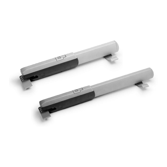
UNI EN ISO 14001 a garanzia del rispetto e della tutela dell’ambiente. Vi chiediamo di continuare l’opera di tutela dell’ambiente, che CAME considera uno dei fondamenti di sviluppo delle proprie strategie operative e di mercato, semplicemente osservando brevi indicazioni in materia di smaltimento: SMALTIMENTO DELL’IMBALLO... - Page 6 DATI E INFORMAZIONI SUL PRODOTTO Legenda Questo simbolo indica parti da leggere con attenzione. Questo simbolo indica parti riguardanti la sicurezza. Questo simbolo indica cosa comunicare all’utente. Le misure, se non diversamente indicato, sono in millimetri. Descrizione 001A3000 Motoriduttore 230 V irreversibile con micro di fi necorsa di apertura per cancelli a battente con anta fi no a 3 m e 400 kg di peso.
-
Page 7: Descrizione Delle Parti
Destinazione d'uso Soluzione per applicazioni residenziali e condominiali Ogni installazione e uso diff ormi da quanto indicato nel seguente manuale sono da considerarsi vietate. Descrizione delle parti Sportello per l'accesso al meccanismo di sblocco Staff a di fi ssaggio al cancello Snodo Staff a di fi... -
Page 8: Limiti Di Impiego
Dimensioni A3000 A3000A A3010 A3006 A3100 A3106 A5000 A5000A A5006 A5010 A5100 A5106 Limiti di impiego MODELLI A3000 Lunghezza anta (m) Peso anta (kg) MODELLI A5000 Lunghezza anta (m) Peso anta (kg) Per ante di lunghezza superiore a 2,5 m si consiglia l'installazione di un'elettroserratura. -
Page 9: Dati Tecnici
Dati tecnici MODELLI A3000 A3000A A3010 A3006 A3100 A3106 230 AC 230 AC 110 AC 230 AC 230 AC 230 AC Alimentazione motore (V) 50/60 Hz 50/60 Hz 50/60 Hz 50/60 Hz 50/60 Hz 50/60 Hz Potenza (W) Condensatore (μF) Corrente assorbita (A) Temperatura d’esercizio (°C) - Page 10 Tipi di cavi e spessori minimi Lunghezza del cavo (m) fi no a 20 da 20 a 30 Alimentazione 230 V AC 3G x 1,5 mm² 3G x 2,5 mm² Alimentazione motore 230 V AC 4G x 1,5 mm² 4G x 2,5 mm² Con alimentazione a 230 V e utilizzo in ambiente esterno, utilizzare cavi tipo H05RN-F conformi alla 60245 IEC 57 (IEC);...
-
Page 11: Installazione
INSTALLAZIONE Le seguenti illustrazioni sono solo esempi in quanto lo spazio per il fi ssaggio dell’automazione e degli accessori varia a seconda della zona di installazione. Spetta all’installatore scegliere la soluzione più adatta. I disegni si riferiscono al motoriduttore installato a sinistra. Operazioni preliminari Preparare le scatole di derivazione e i tubi corrugati necessari per i collegamenti provenienti dal pozzetto di derivazione. - Page 12 Determinazione dei punti di fissaggio delle staffe Rispettare le quote indicate nella tabella. A3000 A3006 A3010 A3100 A3106 Apertura anta (°) C Max A5000 A5006 A5010 A5100 A5106 Apertura anta (°) C Max...
- Page 13 Fissaggio delle staffe Fissare la piastra di fi ssaggio al pilastro con tasselli e viti. Se il pilastro è di metallo, la piastra di fi ssaggio al pilastro deve essere saldata. Saldare la staff a di fi ssaggio al pilastro alla piastra di fi ssaggio. I fori sulla staff a di fi...
- Page 14 A cancello chiuso, fi ssare la piastra di fi ssaggio e la staff a di fi ssaggio al cancello. La staff a di fi ssaggio al cancello e quella di fi ssaggio al pilastro devono essere in asse orizzontale. Rispettare la misura E riportata in tabella.
-
Page 15: Fissaggio Del Motoriduttore
Fissaggio del motoriduttore Svitare le due viti di fi ssaggio e rimuovere il carter. Svitare le due viti di fi ssaggio e rimuovere lo stelo. Fissare il motoriduttore alle due staff e. Lubrifi care bene, con grasso neutro, la vite senza fi ne e la boccola. - Page 16 Regolazione dei micro di finecorsa di apertura e di chiusura Solo i modelli A3000A e A5000A hanno i micro di fi necorsa sia di apertura sia di chiusura. Tutti gli altri modelli hanno solo il micro di fi necorsa di apertura. Microinterruttore di fi...
-
Page 17: Collegamenti Elettrici
COLLEGAMENTI ELETTRICI Prima di intervenire sul quadro di comando, togliere la tensione di linea. Per poter accedere alla morsettiera, togliere la copertura di protezione. Per motivi di ingombro, i condensatori delle versioni 110 V vanno messi nel quadro. Collegamento di 2 motori al quadro comando ZA3P o ZM3E. 1 2 3 4 T.L. - Page 18 Collegamento di 1 motore al quadro comando ZA3P o ZM3E. 1 2 3 4 T.C.A. T.L. TR2M. 3 4 5 6 7 8 9 10 FUSIBILE CENTRALINA FUSIBILI LINEA 5A QUADRO COMANDO C1 CX B1 B2...
- Page 19 Apertura max cancello: 90°. Fissare la staff a di fi ssaggio al cancello. Eseguire i collegamenti elettrici. Riposizionare e regolare il gruppo microinterruttore di stop in apertura. Rispettare le quote indicate nella tabella. A3000 A3006 A3010 A3100 A3106 Apertura anta (°)
- Page 20 Il gruppo microinterruttore di stop in apertura va riposizionato perchè quando il cancello è aperto il gruppo microinterruttore è in punta del pistone e serve allungare il cavo (non fornito). CAME S.p.A. Via Martiri della Libertà, 15 31030 Dosson di Casier Treviso - Italy Tel.
- Page 21 FA01810-EN A3000 A3010 A5000 A5010 A3000A A3100 A5000A A5100 A3006 A3106 A5006 A5106 INSTALLATION MANUAL English...
- Page 23 fi nal installation to comply with the Machinery Directive (2006/42/EC) and with the reference harmonised technical standards are specifi ed in the general CAME product catalogue or on the website www.came.com. • Make sure the mains power supply is disconnected during all installation procedures.
- Page 24 The manufacture date is provided in the production batch printed on the product label. If necessary, contact us at https://www.came.com/global/en/contact-us. The general conditions of sale are given in the offi cial CAME price lists.
-
Page 25: Dismantling And Disposal
UNI EN ISO 14001 standard to ensure that the environment is respected and safeguarded. Please continue safeguarding the environment. At CAME we consider it one of the fundamentals of our operating and market strategies. Simply follow these brief disposal guidelines: DISPOSING OF THE PACKAGING The packaging materials (cardboard, plastic, etc.) can be disposed of easily as solid urban waste, separated for recycling. - Page 26 PRODUCT DATA AND INFORMATION This symbol shows which parts to read carefully. This symbol shows which parts describe safety issues. This symbol shows what to tell users. The measurements, unless otherwise stated, are in millimetres. Description 001A3000 Irreversible gearmotor 230 V with opening micro limit switch for swing gates with leaf up to 3 m and 400 kg. 001A3000A Irreversible gearmotor 230 V with opening and closing micro limit switch for swing gates with leaf up to 3 m and 400 kg.
-
Page 27: Intended Use
Intended use Solutions for applications in residential buildings and apartment blocks Any installation and/or use other than that specifi ed in this manual is forbidden. Description of parts Door to access the release mechanism Gate bracket Coupling Pillar bracket Anchoring plate... -
Page 28: Usage Limitations
Size A3000 A3000A A3010 A3006 A3100 A3106 A5000 A5000A A5006 A5010 A5100 A5106 Usage limitations MODELS A3000 Gate-leaf length (m) Leaf weight (kg) MODELS A5000 Gate-leaf length (m) Leaf weight (kg) For leaves longer than 2.5 m, install an electric lock. -
Page 29: Technical Data
Technical data MODELS A3000 A3000A A3010 A3006 A3100 A3106 230 AC 230 AC 110 AC 230 AC 230 AC 230 AC Motor power supply (V) 50/60 Hz 50/60 Hz 50/60 Hz 50/60 Hz 50/60 Hz 50/60 Hz Power (W) Capacitor (μF) Current draw (mA) Operating temperature (°C) - Page 30 Cable types and minimum thicknesses Cable length (m) up to 20 from 20 to 30 Power supply 230 V AC 3G x 1.5 mm² 3G x 2.5 mm² Motor power supply 230 V AC 4G x 1.5 mm² 4G x 2.5 mm² When operating at 230 V and outdoors, use H05RN-F cables compliant with 60245 IEC 57 (IEC);...
-
Page 31: Installation
INSTALLATION The following illustrations are examples only. The space available for fi tting the operator and accessories varies depending on the area where it is installed. It is up to the installer to fi nd the most suitable solution. The drawings refer to a gearmotor installed on the left-hand side. Preliminary operations Prepare the junction boxes and corrugated tubes you need for the connections from the junction pit. - Page 32 Deciding where to fasten the brackets Respect the values indicated in the table. A3000 A3006 A3010 A3100 A3106 Gate-leaf opening (°) Max. C A5000 A5006 A5010 A5100 A5106 Gate-leaf opening (°) Max. C...
-
Page 33: Fastening The Brackets
Fastening the brackets Secure the anchoring plate to the pillar with plugs and screws. If there is a metal post instead of a pillar, the anchoring plate must be welded to the post. Weld the post bracket to the anchoring plate. The holes in the pillar bracket allow you to vary the opening angle of the gate leaf. - Page 34 With the gate closed, fasten the anchoring plate and bracket to the gate. The gate bracket and pillar bracket must be aligned horizontally. Please respect measurement E as listed in the table.
- Page 35 Fastening the gearmotor Unscrew the two screws and remove the casing. Unscrew the two screws and remove the shaft. Fasten the gearmotor to the two brackets. Lubricate the endless screw and bushing well using a neutral grease.
- Page 36 Adjusting the opening and closing micro limit switches Only the A3000A and A5000A models have both opening and closing micro limit switches. All other models only have an opening micro limit switch. Opening micro limit switch Closing micro limit switch Microswitch activation slider Endless screw Microswitch support boom...
-
Page 37: Electrical Connections
ELECTRICAL CONNECTIONS Before working on the control panel, cut off the mains power supply. Remove the protective cover to access the terminal block. For space reasons, capacitors for the 110 V versions should be connected to the control panel. Connecting 2 motors to a ZA3P or ZM3E control panel. 1 2 3 4 T.L. - Page 38 Connecting 1 motor to a ZA3P or ZM3E control panel. 1 2 3 4 T.C.A. T.L. TR2M. 3 4 5 6 7 8 9 10 FUSIBILE CENTRALINA FUSIBILI LINEA 5A QUADRO COMANDO C1 CX B1 B2...
- Page 39 Open the gate and measure length E. Maximum gate opening: 90°. Fasten the bracket to the gate. Make the electrical connections. Reposition and adjust the opening stop microswitch assembly. Respect the values indicated in the table. A3000 A3006 A3010 A3100 A3106 Gate-leaf opening (°)
- Page 40 Reposition the opening stop microswitch assembly because when the gate is open the microswitch assembly is at the end of the piston and the wire needs to be extended (not supplied). CAME S.p.A. Via Martiri della Libertà, 15 31030 Dosson di Casier Treviso –...
-
Page 41: Manuel D'installation
FA01810-FR A3000 A3010 A5000 A5010 A3000A A3100 A5000A A5100 A3006 A3106 A5006 A5106 MANUEL D'INSTALLATION Français... - Page 43 à la mise en conformité de l'installation fi nale selon la directive Machines 2006/42/CE et les normes techniques harmonisées de référence sont identifi és dans le catalogue général des produits CAME ou sur le site www. came.com. • S’assurer, durant toutes les phases d’installation, que l’automatisme est bien hors tension.
- Page 44 La data de fabrication est indiquée dans le lot de production imprimé sur l’étiquette du produit. Si nécessaire, nous contacter à l’adresse https://www.came.com/global/en/contact- Les conditions générales de vente fi gurent dans les catalogues de prix offi ciels Came.
-
Page 45: Références Normatives
MISE AU REBUT ET ÉLIMINATION CAME S.p.A. adopte dans ses établissements un Système de Gestion Environnementale certifi é et conforme à la norme UNI EN ISO 14001 qui garantit le respect et la sauvegarde de l'environnement. Nous vous demandons de poursuivre ces eff orts de sauvegarde de l'environnement, que CAME considère comme l'un des fondements du développement... - Page 46 DONNÉES ET INFORMATIONS SUR LE PRODUIT Légende Ce symbole indique des parties à lire attentivement. Ce symbole indique des parties concernant la sécurité. Ce symbole indique ce qui doit être communiqué à l'utilisateur. Les dimensions sont exprimées en millimètres, sauf indication contraire. Description 001A3000 Motoréducteur 230 V irréversible avec micro-interrupteur de fi...
-
Page 47: Utilisation Prévue
Utilisation prévue Solution pour applications résidentielles et collectives Toute installation et toute utilisation autres que celles qui sont indiquées dans ce manuel sont interdites. Description des parties Volet d’accès au mécanisme de déblocage Étrier de fi xation au portail Rotule Étrier de fi... -
Page 48: Limites D'utilisation
Dimensions A3000 A3000A A3010 A3006 A3100 A3106 A5000 A5000A A5006 A5010 A5100 A5106 Limites d'utilisation MODÈLES A3000 Longueur vantail (m) Poids vantail (kg) MODÈLES A5000 Longueur vantail (m) Poids vantail (kg) Pour des vantaux de plus de 2,5 m de long, il est conseillé d’installer une serrure de verrouilage électrique. -
Page 49: Données Techniques
Données techniques MODÈLES A3000 A3000A A3010 A3006 A3100 A3106 230 AC 230 AC 110 AC 230 AC 230 AC 230 AC Alimentation moteur (V) 50/60 Hz 50/60 Hz 50/60 Hz 50/60 Hz 50/60 Hz 50/60 Hz Puissance (W) Condensateur (μF) Courant absorbé... - Page 50 Types de câbles et épaisseurs minimum Longueur du câble (m) jusqu’à 20 de 20 à 30 Alimentation 230 VAC 3G x 1,5 mm² 3G x 2,5 mm² Alimentation moteur 230 VAC 4G x 1,5 mm² 4G x 2,5 mm² En cas d’alimentation en 230 V et d’une utilisation en extérieur, adopter des câbles H05RN-F conformes à la norme 60245 IEC 57 (IEC) ;...
-
Page 51: Opérations Préliminaires
INSTALLATION Les illustrations suivantes ne sont que des exemples étant donné que l'espace pour la fi xation de l'automatisme et des accessoires varie en fonction de la zone d'installation. C'est donc l'installateur qui doit choisir la solution la plus indiquée. Les dessins se réfèrent au motoréducteur installé... - Page 52 Détermination des points de fixation des étriers Respecter les dimensions indiquées dans le tableau. A3000 A3006 A3010 A3100 A3106 Ouverture vantail (°) C Max. A5000 A5006 A5010 A5100 A5106 Ouverture vantail (°) C Max.
- Page 53 Fixation des étriers Fixer la plaque de fi xation au pilier à l’aide de chevilles et de vis. En cas de pilier en métal, il faut souder la plaque de fi xation au pilier. Souder l'étrier de fi xation au pilier à la plaque de fi xation. Les trous prévus sur l'étrier de fi...
- Page 54 Avec le portail fermé, fi xer la plaque de fi xation et l'étrier de fi xation au portail. L'étrier de fi xation au portail et l'étrier de fi xation au pilier doivent être sur un axe horizontal. Respecter la mesure E indiquée dans le tableau.
-
Page 55: Fixation Du Motoréducteur
Fixation du motoréducteur Dévisser les deux vis de fi xation et enlever le carter. Dévisser les deux vis de fi xation et enlever la tige. Fixer le motoréducteur aux deux étriers. Bien lubrifi er la vis sans fi n et la douille avec de la graisse neutre. - Page 56 Réglage des micro-interrupteurs de fin de course d’ouverture et de fermeture Seuls les modèles A3000A et A5000A ont les micro-interrupteurs de fi n de course aussi bien d'ouverture que de fermeture. Tous les autres modèles n'ont que le micro-interrupteur de fi n de course d'ouverture. Micro-interrupteur de fi...
-
Page 57: Branchements Électriques
BRANCHEMENTS ÉLECTRIQUES Avant d'intervenir sur l’armoire de commande, la mettre hors tension. Pour pouvoir accéder au bornier, enlever le couvercle de protection. Pour des raisons d'espace, les condensateurs des versions 110 V doivent être placés dans l'armoire. Connexion de 2 moteurs à l'armoire de commande ZA3P ou ZM3E. 1 2 3 4 T.L. - Page 58 Connexion d'1 moteur à l'armoire de commande ZA3P ou ZM3E. 1 2 3 4 T.C.A. T.L. TR2M. 3 4 5 6 7 8 9 10 FUSIBILE CENTRALINA FUSIBILI LINEA 5A QUADRO COMANDO C1 CX B1 B2...
- Page 59 Ouverture max. portail : 90°. Fixer l'étrier de fi xation au portail. Eff ectuer les branchements électriques. Repositionner et régler le groupe micro-interrupteur d'arrêt à l'ouverture. Respecter les dimensions indiquées dans le tableau. A3000 A3006 A3010 A3100 A3106 Ouverture vantail (°)
- Page 60 Il faut repositionner le groupe micro-interrupteur d'arrêt à l'ouverture car, lorsque le portail est ouvert, le groupe du micro-interrupteur se trouve à la pointe du piston et il faut rallonger le câble (non fourni). CAME S.p.A. Via Martiri della Libertà, 15...
-
Page 61: Руководство По Монтажу
FA01810-RU A3000 A3010 A5000 A5010 A3000A A3100 A5000A A5100 A3006 A3106 A5006 A5106 РУКОВОДСТВО ПО МОНТАЖУ Русский... - Page 63 профили и т. д.), необходимые для обеспечения соответствия конечной установки Директиве о безопасности машин и оборудования 2006/42/CE и гармонизированным техническим стандартам, указаны в общем каталоге продукции CAME или на сайте www.came.com. • Убедитесь в отсутствии напряжения перед каждым этапом монтажных работ. • Убедитесь...
- Page 64 в закрытом виде (в железнодорожных вагонах, контейнерах, закрытом автотранспорте). В случае обнаружения неисправности изделия необходимо прекратить его эксплуатацию и связаться с сервисной службой по адресу https://www.came.com/global/en/contact-us или позвонить по номеру, указанному на сайте. Дата изготовления указана в партии продукции, напечатанной на этикетке изделия.
- Page 65 Изделие соответствует требованиям применяемых действующих директив. УТИЛИЗАЦИЯ CAME S.p.A. имеет сертификат системы защиты окружающей среды UNI EN ISO 14001, гарантирующий экологическую безопасность на ее заводах. Мы просим вас прилагать максимальные усилия по защите окружающей среды. Компания САМЕ считает одним из фундаментальных пунктов стратегии рыночных отношений выполнение этих...
-
Page 66: Условные Обозначения
ДАННЫЕ И ИНФОРМАЦИЯ ОБ ИЗДЕЛИИ Условные обозначения Этот символ обозначает раздел, требующий особого внимания. Этот символ обозначает раздел, связанный с вопросами безопасности. Этот символ обозначает раздел, предназначенный для ознакомления конечного пользователя. Все размеры приведены в мм, если не указано иное. Описание... -
Page 67: Описание Компонентов
Назначение Решение для частных жилых домов и кондоминиумов Запрещено использовать устройство не по назначению и устанавливать его методами, не описанными в этой инструкции. Описание компонентов Дверца для доступа к механизму разблокировки Кронштейн крепления к воротам Шарнир Кронштейн крепления к столбу Монтажное... -
Page 68: Габаритные Размеры
Габаритные размеры A3000 A3000A A3010 A3006 A3100 A3106 A5000 A5000A A5006 A5010 A5100 A5106 Ограничения по применению МОДЕЛИ A3000 Ширина створки (м) Масса створки (кг) МОДЕЛИ A5000 Ширина створки (м) Масса створки (кг) Для створки длиной свыше 2,5 м рекомендуется устанавливать электрозамок. - Page 69 Технические характеристики МОДЕЛИ A3000 A3000A A3010 A3006 A3100 A3106 ~230 ~230 ~110 ~230 ~230 ~230 Электропитание привода (В) (50/60 Гц) (50/60 Гц) (50/60 Гц) (50/60 Гц) (50/60 Гц) (50/60 Гц) Мощность (Вт) Конденсатор (мкФ) Потребляемый ток (A) Диапазон рабочих температур -20 ÷ +55 -20 ÷ +55 -20 ÷...
- Page 70 Тип и минимальное сечение кабелей Длина кабеля (м) до 20 от 20 до 30 Напряжение электропитания ~230 В 3G x 1,5 мм² 3G x 2,5 мм² Электропитание двигателя, ~230 В 4G × 1,5 мм² 4G × 2,5 мм² При напряжении 230 В и применении вне помещений необходимо использовать кабели типа H05RN-F, соответствующие...
-
Page 71: Предварительные Работы
МОНТАЖ Приведенные ниже рисунки носят иллюстративный характер, поскольку пространство для крепления автоматики и дополнительных принадлежностей может изменяться от случая к случаю. Выбор наиболее подходящего решения должен осуществляться монтажником во время установки. На рисунках показан монтаж привода слева. Предварительные работы Подготовьте разветвительные коробки и гофрированные трубы, необходимые для электрических соединений, идущих от разветвительного... - Page 72 Определение точек крепления кронштейнов Соблюдайте установочные расстояния, указанные в таблице. A3000 A3006 A3010 A3100 A3106 Угол открывания C макс. створки (°) A5000 A5006 A5010 A5100 A5106 Угол открывания C макс. створки (°)
- Page 73 Монтаж кронштейнов Прикрепите монтажную пластину к столбу дюбелями и винтами. Если столб ворот изготовлен из металла, монтажную пластину следует к нему приварить. Приварите задний кронштейн к столбу с монтажной пластиной. Отверстия в заднем кронштейне крепления к столбу позволяют дополнительно изменять угол открывания створки.
- Page 74 Закрыв ворота, приварите передний кронштейн с монтажной пластиной к створке ворот. Передний кронштейн и задний кронштейн должны располагаться на одной горизонтальной оси. Соблюдайте расстояние Е, указанное в таблице.
- Page 75 Крепление привода Отверните два крепежных винта и снимите крышку. Отверните два крепежных винта и снимите корпус. Установите привод на передний и задний кронштейны. Тщательно смажьте нейтральной смазкой ходовой винт и втулку.
- Page 76 Регулировка концевых микровыключателей открывания и закрывания Только у моделей A3000A и A5000A есть концевые микровыключатели как открывания, так и закрывания. Все другие модели оснащены только концевыми микровыключателями открывания. Концевой микровыключатель открывания Концевой микровыключатель закрывания Каретка активации микровыключателя Ходовой винт Направляющая микровыключателей Крепежный...
-
Page 77: Электрические Подключения
ЭЛЕКТРИЧЕСКИЕ ПОДКЛЮЧЕНИЯ Перед началом работ с блоком управления отключите сетевое электропитание. Чтобы получить доступ к контактной панели, снимите защитную крышку. Из соображений эргономичности конденсаторы версий 110 В должны располагаться в блоке управления. Подключение 2 приводов к блоку управления ZA3P или ZM3E. 1 2 3 4 T.L. - Page 78 Подключение 1 привода к блоку управления ZA3P или ZM3E. 1 2 3 4 T.C.A. T.L. TR2M. 3 4 5 6 7 8 9 10 FUSIBILE CENTRALINA FUSIBILI LINEA 5A QUADRO COMANDO C1 CX B1 B2...
- Page 79 Откройте ворота и определите расстояние E. Макс. градус открывания ворот: 90°. Передний кронштейн крепления к воротам. Выполните электрические подключения. Установите и отрегулируйте положение группы микровыключателя открывания. Соблюдайте установочные расстояния, указанные в таблице. A3000 A3006 A3010 A3100 A3106 Угол открывания створки...
- Page 80 C1 CX B1 B2 Группу концевого микровыключателя открывания необходимо переместить, так как, когда ворота открыты, группа концевого микровыключателя располагается на конце оси и требует удлинения кабеля (не прилагается). CAME S.p.A. Via Martiri della Libertà, 15 31030 Доссон-ди-Казьер Treviso - Italy (Италия) Тел.: (+39) 0422 4940...
Need help?
Do you have a question about the A3000 and is the answer not in the manual?
Questions and answers