
Related Manuals for CAME ATI series


Summary of Contents for CAME ATI series
- Page 1 AUTOMAZIONE 119DV74 DV74IT PER CANCELLI A BATTENTE Italiano English Français Русский MANUALE D’INSTALLAZIONE A3000A A5000A Italiano...
-
Page 2: Installazione
Avvertimento (es. targa cancello). stato espressamente concepito. Ogni altro uso è da conside- Istruzioni e raccomandazioni rarsi quindi pericoloso. La CAME cancelli automatici s.p.a. non particolari per gli utenti è responsabile per eventuali danni causati da usi impropri, er- • Tenete libere da ingombri e pulite le aree di manovra del can- ronei ed irragionevoli •... -
Page 4: Legenda Simboli
5.00 3 Riferimenti normativi CAME cancelli automatici è una azienda certificata per il sistema di gestione della qualità aziendale ISO 9001 e di gestione ambientale ISO 14001. Il prodotto in oggetto è conforme alle seguenti normative: vedi Dichiarazione di Conformità... - Page 5 4.3 Descrizione delle parti 1) Motoriduttore 2) Staff a di testa 3) Snodo di coda 4) Staff a di coda 5) Piastra di fi ssaggio 4.4 Misure d’ingombro A5000A A3000A Corsa Corsa 5 Installazione 5.1 Verifiche preliminari Prima di procedere all’installazione dell’automazione è necessario verificare che: •...
-
Page 6: Impianto Tipo
5.2 Attrezzi e materiali Assicurarsi di avere tutti gli strumenti ed il materiale necessario, per effettuare l’installazione nella massima sicurezza, secondo le normative vigenti. Di seguito in figura l’attrezzatura minima per l’installatore. 5.3 Tipologia cavi e spessori minimi Lunghezza cavo Lunghezza cavo Lunghezza cavo Collegamento... - Page 7 5.5 Montaggio Le applicazioni che seguono sono solo esempi, in quanto lo spazio per il fissaggio dell’automazione de gli accessori varia a seconda degli ingombri. Spetta quindi all’installatore scegliere la soluzione più idonea. Tab. 3 Pilastro Anta posizione Ante < 3 m chiusa Cerniera C <...
- Page 8 Piastra di fi ssaggio Livellare la staff a Staff a di testa A cancello chiuso applicare sull’anta la piastra di fissaggio, verificando che la staffa di testa sia in asse orizzontale con la staffa di coda e rispettando la misura E. Carter Svitare le due viti di fi...
- Page 9 5.6 Sblocco a chiave personalizzata Chiave Sportellino Lo sblocco va effettuato a motore fermo: 1) sollevare lo sportellino; 2) inserire e girare la chiave che istantaneamente sblocca l’anta; 3) spingere o tirare l’anta manualmente. Per bloccare nuovamente l’anta è sufficiente reinserire e girare la chiave.
- Page 10 5.8 Collegamento ai quadri comando ZA3N/ZM3E Collegamento 2 motori Collegamento 1 motore...
- Page 11 5.9 Applicazione per apertura verso l’esterno Tab. 4 A3000A A5000A 130 mm 200 mm 130 mm 200 mm 720 mm 920 mm Esterno Interno Staff a supplementare - Rilevare le quote A e B (Tab.4). - Fissare la staff a di coda a una staff a supplementare e applicarla al pilastro. - Aprire il cancello (max 90°), rilevare la quota E (Tab.4) e fi...
-
Page 12: Indicazioni Di Sicurezza
6 Indicazioni di sicurezza Importanti indicazioni di sicurezza generali Questo prodotto deve essere destinato solo all’uso per il quale è stato espressamente studiato. Ogni altro uso è da considerarsi improprio e quindi pericoloso. Il costruttore non può essere considerato responsabile per eventuali danni causati da usi impropri, erronei e irragionevoli. -
Page 13: Manutenzione Periodica
7 Manutenzione 7.1 Manutenzione periodica Gli interventi periodici a cura dell’utente sono: pulizia dei vetrini delle fotocellule; controllo del corretto funzionamento dei dispositivi di sicurezza; rimozione di eventuali intralci al corretto funzionamento dell’automazione. È consigliabile un controllo periodico della lubrificazione e dell’eventuale allentamento delle viti di fissaggio dell’automazione. Per controllare l’efficienza dei dispositivi di sicurezza, passare un oggetto davanti alle fotocellule durante la movimentazione in fase di chiusura. -
Page 14: Manutenzione Straordinaria
Registro manutenzione periodico a cura dell’utente (ogni 6 mesi) Data Annotazioni Firma 7.3 Manutenzione straordinaria La seguente tabella serve per registrare gli interventi di manutenzione straordinaria, di riparazione e di miglioramento eseguiti da ditte esterne specializzate. N.B. Gli interventi di manutezione straordinaria devono essere effettuati da tecnici specializzati. Registro manutenzione straordinaria Timbro installatore Nome operatore... -
Page 15: Demolizione E Smaltimento
UNI EN ISO 14001 a garanzia del rispetto e della tutela dell’ambiente. Vi chiediamo di continuare l’opera di tutela dell’ambiente, che CAME considera uno dei fondamenti di sviluppo delle proprie strategie operative e di mercato, semplicemente osservando brevi indicazioni in materia di smaltimento: SMALTIMENTO DELL’IMBALLO... - Page 16 (+34) 91 52 85 009 127273, Moscow Moscow (+34) 91 46 85 442 (+7) 495 739 00 69 (+7) 495 739 00 69 (ext. 226) CAME United Kingdom Ltd. CAME United Kingdom Ltd. GREAT BRITAIN PORTUGAL CAME Portugal CAME Portugal...
- Page 17 AUTOMATION 119DV74EN FOR SWING GATES INSTALLATION MANUAL A3000A A5000A English...
-
Page 18: Read Carefully
Warning Sings (e.g. gate plate). (i.e. that for which it was expressly built for). Any other use is Special instructions and to be considered dangerous. Came Cancelli Automatici S.p.A. advice for users is not liable for any damage resulting from improper, wrongful •... -
Page 20: Legend Of Symbols
4.00 5.00 3 Reference Standards For its quality processes management Came Cancelli Automatici is ISO 9001 certified, and for its environmental management it is ISO 14001 certified. This product complies with the following standards: see declaration of conformity. 4 Description 4.1 Gearmotor... - Page 21 4.3 Description of parts 1) Gearmotor 2) Front bracket 3) Back swivel-joint 4) Back bracket 5) Anchoring plate 4.4 Overall dimensions A5000A A3000A Travel Travel 5 Installation 5.1 Preliminary checks Before installing, do the following: • make sure the structure of the gate is sturdy, the hinges work and that there is no friction between moving parts and non-moving parts;...
-
Page 22: Tools And Materials
5.2 Tools and materials Make sure you have all the tools and materials you will need for the installation at hand to work in total safety and compliance with the current standards and regulations. 5.3 Cable list and minimum thickness Length of cable Length of cable Length of cable... - Page 23 5.5 Mounting The following applications are only examples, in that the space available for fixing the operator and accessories varies depen- ding on the dimensions. It is thus up to the installer to choose the most suitable solution. Tab. 3 Pillar Leaf - closed Gate leaves <...
- Page 24 Anchoring plate Level the bracket Front bracket With the gate closed apply the anchoring plate to the gate leaf, making sure that the front bracket is lined up horizontally with the back bracket and ensuring that measurement E is met. Carter Unscrew the two screws and remove the carter.
- Page 25 5.6 Release with customised key Door Release only with motor stopped: 1) raise the door; 2) insert and turn key which immediately releases door; 3) manually push or pull gate leaf. To lock gate leaf again into place just insert key again and turn.
- Page 26 5.8 Connecting to the ZA3N/ZM3E control panels Connecting 2 motors Connecting 1 motor...
- Page 27 5.9 Application for outward opening Tab. 4 A3000A A5000A 130 mm 200 mm 130 mm 200 mm 720 mm 920 mm Outward Inward Extra bracket - Measure values A and B (Tab. 4) - Secure the tail bracket to an extra bracket and apply to post. - Open gate (max 90°), measure value E (Tab.
-
Page 28: Safety Instructions
6 Safety instructions Important safety instructions This product must only be employed for its originally intended use. Any other use is wrong and potentially dangerous. The manufacturer cannot be held liable for any damages resulting from wrongful, erroneous or negligent uses. Avoid working close to the hinges or other moving mechanical parts. -
Page 29: Periodic Maintenance
7 Maintenance 7.1 Periodic maintenance Periodic maintenance to be carried out by the end-user is as follows: wipe clean the glass surface of the photocells; check that the safety devices work properly; remove any obstructions. We suggest checking the state of lubrication and tightness of the anchoring screws on the operator. To check the efficiency of the safety devices, move an object in front of the photocells when gate is closing. -
Page 30: Extraordinary Maintenance
Periodic maintenance log for end-user (every 6 moths) Signature Date Notes 7.3 Extra-ordinary maintenance The following table serves to note down any extraordinary maintenance, repairs or improvements performed by specialised firms. N.B.: Any extraordinary maintenance must be performed by specialised technicians. Extra-ordinary maintenance log Installer’s stamp Operator name... -
Page 31: Phasing Out And Disposal
CAME CANCELLI AUTOMATICI S.p.A. employs a UNI EN ISO 14001 certified and compliant environmental protection system at its plants, to ensure that environmental safeguarding. We ask you to keep protecting the environment, as CAME deems it to be one of the fundamental points of its market operations strategies, by simply following these brief guidelines when disposing: DISPOSING THE PACKING MATERIALS The packing components (cardboard, plastic, etc.) are solid urban waste and may be disposed of without any particular difficulty, by... - Page 32 (+34) 91 52 85 009 127273, Moscow Moscow (+34) 91 46 85 442 (+7) 495 739 00 69 (+7) 495 739 00 69 (ext. 226) CAME United Kingdom Ltd. CAME United Kingdom Ltd. GREAT BRITAIN PORTUGAL CAME Portugal CAME Portugal...
- Page 33 AUTOMATISME 119DV74FR POUR PORTAILS BATTANTS MANUEL D’INSTALLATION A3000A A5000A Français...
- Page 34 • Conservez la zone de manœuvre du portail propre et sans rien lequel il a été spécifi quement conçu. Tout autre usage sera donc considéré comme dangereux. La société CAME Cancelli qui risque de l’encombrer. Retirez la végétation se trouvant dans Automatici S.p.A.
-
Page 36: Légende Des Symboles
5.00 3 Normes de référence Came Cancelli Automatici est une entreprise certifiée par le Système de Contrôle Qualité des Entreprises ISO 9001 et de Gestion de l’Environnement ISO 14001. Le produit en objet est conforme aux normes suivantes : voir déclaration de conformité. -
Page 37: Description Des Éléments
4.3 Description des éléments 1) Motoréducteur 2) Étrier de tête 3) Articulation de queue 4) Étrier de queue 5) Plaque de fi xage 4.4 Mesure d’encombrement A5000A A3000A Course Course 5 Installation 5.1 Contrôles préliminaires Avant de procéder au montage, il est nécessaire de vérifier que : •... -
Page 38: Outils Et Matériel
5.2 Outils et matériel Assurez-vous d’avoir tous les outils et le matériel nécessaire pour effectuer le montage de l’automatisme en toute sécurité et conformément aux normes en vigueur. Sur la planche, quelques exemples de matériel pour l’installateur. 5.3 Types de cables et epaisseurs minimales Longueur câble Longueur câble Longueur câble... -
Page 39: Montage
5.5 Montage Les applications suivantes ne sont que des exemples, étant donné que l’espace pour le fixage de l’automatisme et de ses ac- cessoires varie selon les encombrements, c’est donc l’installateur qui doit choisir la solution la plus appropriée. Tab. 3 Pilier Vantail position Vantaux <... - Page 40 Plaque de fi xage Mettre l’étrier au même niveau Étrier de tête Avec le portail fermé, placez la plaque de fixage sur le vantail, après avoir contrôlé que l’étrier de tête est sur le même axe horizon- tal que l’étrier de queue et en respectant la mesure E. Carter Dévissez les deux vis de fi...
- Page 41 5.6 Déverrouillage avec clé personnalisée. Clé Volet Le déverrouillage doit s’effectuer avec le moteur à l’arrêt : 1) soulevez le volet; 2) introduisez et tournez la clé qui déverrouille instantané- ment le vantail; 3) poussez ou tirez le vantail manuellement. Pour verrouiller de nouveau le vantail il suffit d’introduire une autre fois la clé...
- Page 42 5.8 Connexion armoires de commande ZA3N/ZM3E Connexion 2 moteurs Connexion 1 moteurs...
- Page 43 5.9 Application pour ouverture vers l’extérieur Tab. 4 A3000A A5000A 130 mm 200 mm 130 mm 200 mm 720 mm 920 mm Extérieur Intérieur Etrier supplémentaire - Relevez les données A et B (Tableau 4). - Fixez l’étrier de queue à un étrier supplémentaire et appliquez-le au pilier. - Ouvrez le portail (max.
- Page 44 6 Consignes pour la sécurité Consignes générales importantes pour la sécurité Ce produit doit être utilisé seulement pour le service pour lequel il a été spécialement conçu. Toute autre utilisation sera considérée impropre et donc dangereuse. Le constructeur décline sa responsabilité pour les dommages éventuellement causés par des utilisations inexactes, incorrectes et irrationnelles.
- Page 45 7 Maintenance 7.1 Maintenance périodique Les opérations périodiques à la charge de l’utilisateur sont : nettoyage des lamelles de verre des photocellules, contrôle de l’état de marche des dispositifs de sécurité; élimination de tout ce qui peut empêcher le fonctionnement conforme de l’automatisme. Il est conseillé...
- Page 46 Registre de maintenance périodique à la charge de l’usager (tous les 6 mois) Date Remarques Signature 7.3 Maintenance extraordinaire Ce tableau est destiné à l’enregistrement des opérations de maintenance extraordinaire, de réparation ou d’amélioration, effectuées par des entreprises externes spécialisées. N.B.
- Page 47 à la norme UNI EN ISO 14001 pour garantir le respect et la sauvegarde de l’environnement. L’usager est prié de continuer cet effort de sauvegarde de l’environnement que Came considère comme un des facteurs de développement de ses stratégies de fabrication et commerciales, en suivant ces brèves indications concernant le recyclage: ÉLIMINATION DE L’EMBALLAGE...
- Page 48 (+34) 91 52 85 009 127273, Moscow Moscow (+34) 91 46 85 442 (+7) 495 739 00 69 (+7) 495 739 00 69 (ext. 226) CAME United Kingdom Ltd. CAME United Kingdom Ltd. GREAT BRITAIN PORTUGAL CAME Portugal CAME Portugal...
-
Page 49: Инструкция По Установке
АВТОМАТИКА 119DV74RU ДЛЯ РАСПАШНЫХ ВОРОТ ИНСТРУКЦИЯ ПО УСТАНОВКЕ A3000A A5000A Русский... - Page 50 видном месте, где это необходимо, предупреждающие знаки (например, табличку ворот). Любое другое применение, не предусмотренное в данной инструкции, рассматривается как опасное. CAME cancelli automatici S.p.A. снимает Специальные инструкции и рекомендации с себя какую-либо ответственность за возможный ущерб, нанесенный для пользователей...
-
Page 52: Условные Обозначения
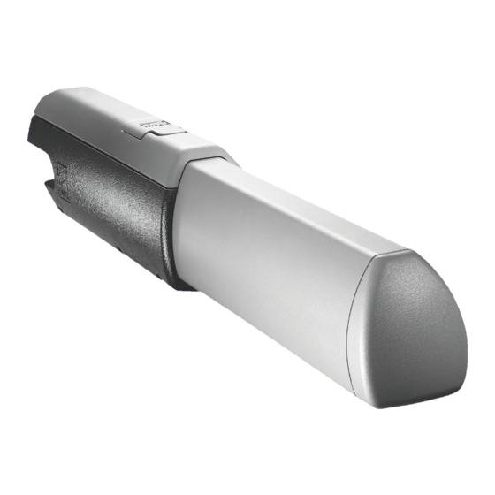
Изделие соответствует требованиям следующих стандартов: смотрите декларацию о соответствии. 4. Описание 4.1 Привод Это изделие разработано и изготовлено компанией CAME Cancelli Automatici S.p.A в полном соответствии с действующими нормами безопасности. Корпус привода состоит из двух силуминовых частей, внутри которых расположены мотор, редуктор и ходовой винт. Привод... -
Page 53: Основные Компоненты
4.3 Основные компоненты 1) Привод 2) Передний кронштейн 3) Подвижный хвостовик 4) Задний кронштейн 5) Монтажная пластина 4.4 Габаритные размеры A5000A A3000A Длина ходового винта Длина ходового винта 5. Монтаж 5.1 Предварительные проверки Перед началом монтажных работ выполните следующее: • Проверьте, чтобы конструкция ворот была достаточно прочной, петли находились в исправном состоянии, а между подвижными и... - Page 54 5.2 Инструменты и материалы Перед началом монтажных работ следует убедиться в наличии всех необходимых инструментов и материалов, которые позволят произвести установку оборудования в полном соответствии с действующими нормами безопасности. Ниже представлен минимальный набор инструментов для монтажника. 5.3 Тип и минимальное сечение кабелей Длина...
- Page 55 5.5 Монтаж Приведенные ниже рисунки носят иллюстративный характер, так как пространство для крепления автоматики и аксессуаров может меняться от случая к случаю. Таким образом, выбор наиболее подходящего решения должен осуществляться монтажником на месте. Табл. 3 Столб Створка в закрытом Створки < 3 м положении...
- Page 56 Монтажная пластина Выровняйте кронштейн Передний кронштейн Закройте ворота и прикрепите монтажную пластину к створке, убедившись в том, что передний кронштейн расположен на одной горизонтальной оси с задним кронштейном, а также соблюдая расстояние Е. Крышка Отверните два самореза и снимите крышку. Отверните...
- Page 57 5.6 Разблокировка с помощью ключа Ключ Дверца Разблокировка выполняется при отключенном электропитании мотора: 1) приподнимите дверцу; 2) вставьте и поверните ключ; 3) толкните или потяните створку вручную. Чтобы заново заблокировать створку, достаточно повторно вставить и повернуть ключ. 5.7 Регулировка микровыключателей ОТКРЫВАНИЕ...
- Page 58 5.8 Подключение к блокам управления ZA3N/ZM3Е Подключение 2 приводов Подключение 1 привода...
- Page 59 5.9 Монтаж с открыванием наружу Табл. 4 A3000A A5000A 130 mm 200 mm 130 mm 200 mm 720 mm 920 mm Наружняя сторона объекта Внутренняя сторона объекта Дополнительная пластина - Определите расстояния A и B (табл. 4). - Соедините задний кронштейн с дополнительной пластиной и прикрепите конструкцию к столбу. - Откройте...
-
Page 60: Инструкции По Безопасности
6. Инструкции по безопасности Важные инструкции по технике безопасности Это изделие должно использоваться исключительно по прямому назначению. Любое другое применение, не предусмотренное в данной инструкции, рассматривается как опасное. Фирма-изготовитель не несет никакой ответственности за ущерб, нанесенный неправильным использованием системы. Не прикасайтесь к петлям или другим подвижным частям механизма. Не находитесь на пути движения ворот во время работы... -
Page 61: Техническое Обслуживание
7. Техническое обслуживание 7.1 Периодическое техническое обслуживание, осуществляемое пользователем Пользователем должны периодически выполняться следующие работы: чистка фотоэлементов, контроль за исправной работой устройств безопасности и за отсутствием препятствий для работы автоматической системы. Кроме того, рекомендуется периодически контролировать состояние смазки и проверять оборудование на наличие возможного... - Page 62 Бланк регистрации работ по периодическому обслуживанию, заполняемый пользователем (каждые 6 месяцев) Дата Заметки Подпись 7.3 Внеплановое техническое обслуживание Эта таблица необходима для записи внеплановых работ по обслуживанию и ремонту оборудования, выполненных специализированными предприятиями. Важное примечание: ремонт оборудования должен осуществляться квалифицированными специалистами. Бланк...
-
Page 63: Декларация О Соответствии
__________________________________________________________________________________________________ 8. Вывод из эксплуатации и утилизация CAME CANCELLI AUTOMATICI S.p.A. имеет сертификат системы защиты окружающей среды UNI EN ISO 14001, гарантирующий экологическую безопасность на ее заводах. Мы просим, чтобы вы продолжали защищать окружающую среду. САМЕ считает одним из фундаментальных пунктов... - Page 64 (+34) 91 52 85 009 127273, Moscow Moscow (+34) 91 46 85 442 (+7) 495 739 00 69 (+7) 495 739 00 69 (ext. 226) CAME United Kingdom Ltd. CAME United Kingdom Ltd. GREAT BRITAIN PORTUGAL CAME Portugal CAME Portugal...
Need help?
Do you have a question about the ATI series and is the answer not in the manual?
Questions and answers