Advertisement
Quick Links
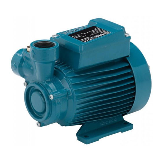
Pompe monoblocco
CT 61
T
TP
,
,
con girante periferica
CA
autoadescanti ad anello liquido
ISTRUZIONI ORIGINALI PER L'USO
1. Condizioni d'impiego
Esecuzione standard
- Per liquidi puliti senza parti abrasive, senza
parti in sospensione, non esplosivi, non ag-
gressivi per i materiali della pompa con tem-
peratura massima di 90°C (60°C per CT 61).
- Elettropompe previste per luoghi aerati e pro-
tetti dalle intemperie con temperatura massi-
ma ambiente di 40°C.
- Avviamenti/ora max.: n. 40 ad intervalli re-
golari.
Potenza nominale motore
fino a kW: 0,5 2,2 4 7,5
Pressione sonora CT,T, TP dB (A) max: 70 75 80 85
CA
dB(A) max: 75 80
- Pressione finale massima ammessa nel corpo
pompa:
CT 61, CA
6 bar
T
12,5 bar
TP
16 bar
2. Installazione
Queste elettropompe monoblocco sono pre-
viste per l'installazione con l'asse del rotore
orizzontale e piedi di appoggio in basso.
Installare la pompa il più vicino possibile alla
fonte di aspirazione.
Prevedere attorno all'elettropompa spazio per
la ventilazione del motore, per ispezioni
e manutenzioni.
3. Tubazioni
Il diametro delle tubazioni non deve essere
inferiore al diametro delle bocche della pompa.
Prima di collegare le tubazioni assicurarsi del-
la loro pulizia interna.
Ancorare le tubazioni su propri appoggi e col-
legarle in modo che non trasmettano forze,
tensioni e vibrazioni alla pompa.
La tubazione aspirante deve essere a
perfetta tenuta e deve avere un andamento
ascendente per evitare sacche d'aria.
Per il funzionamento in aspirazione inserire
una valvola di fondo con succhieruola
che deve risultare sempre immersa.
Con le pompe autoadescanti, serie CA, può
essere montata invece una valvola di
non ritorno sulla bocca di aspira-
zione.
Montare un filtro in aspirazio-
ne per impedire l'ingresso di
corpi estranei nella pompa.
Con l'aspirazione da serbatoio di prima rac-
colta montare una valvola di non ritorno.
Con il funzionamento sotto battente inserire
una saracinesca nella condotta di arrivo.
Per aumentare la pressione della rete di distri-
buzione osservare le prescrizioni locali.
Nella tubazione di mandata installare
una saracinesca per regolare portata, pre-
valenza e potenza assorbita. Installare un in-
dicatore di pressione (manometro).
Quando il dislivello geodetico in mandata è
maggiore di 15 m, tra pompa e saracinesca
inserire una valvola di ritegno per proteg-
gere la pompa da "colpi d'ariete".
4. Collegamento elettrico
Il collegamento elettrico deve esse-
re eseguito da un elettricista qualifi-
cato nel rispetto delle prescrizioni
locali.
Seguire le norme di sicurezza.
Eseguire il collegamento a terra. Col-
legare il conduttore di protezione al morsetto
contrassegnato con il simbolo
.
Confrontare la frequenza e la tensione di rete
con i dati di targa e collegare i con- duttori di
alimentazione ai morsetti secondo il corri-
spondente schema riportato all'interno del co-
perchio della scatola morsetti.
ATTENZIONE: non fare mai ca-
dere una rondella o altre parti
metalliche nel passaggio cavi
interno tra scatola morsetti e statore.
Se accade, smontare il motore e recupe-
rare la parte caduta.
Con motori di potenza ≥ 5,5 kW evitare l'av-
viamento diretto. Prevedere un quadro con
avviamento stella/triangolo o altro dispositi-
vo di avviamento.
Calpeda s.p.a. Via Roggia di Mezzo, 39
36050 Montorso Vicentino - Vicenza - Italia
Tel. +39 - 0444 476 476 Fax +39 - 0444 476 477
Italiano
I motori collegati direttamente alla
rete tramite interruttori termici pos-
sono avviarsi automaticamente.
Installare un dispositivo per la onnipola-
re disinserzione dalla rete (interruttore
per scollegare la pompa dall'alimentazione)
con una distanza di apertura dei contatti di al-
meno 3 mm.
Con alimentazione trifase installare un ade-
guato salvamotore come da corrente di targa.
Le elettropompe monofasi CTM, TM, TPM,
CAM, sono fornite con condensatore colle-
gato ai morsetti e (per 220-240 V - 50 Hz)
con termoprotettore inserito.
5. Avviamento
ATTENZIONE: evitare assolutamente
il funzionamento a secco, neanche
per prova. Avviare la pompa solo dopo
averla riempita completamente di liquido.
Con la pompa sopra il livello dell'acqua
da sollevare (funzionamento in aspirazione)
riempire il tubo aspirante e la pompa attraver-
so l'apposito foro.
Con il livello dell'acqua in aspirazione
sopra la pompa (funzionamento sotto bat-
tente) riempire la pompa aprendo lentamente
e completamente la saracinesca nel tubo
aspirante, tenendo aperta la saracinesca in
mandata per fare uscire l'aria.
Controllare che l'albero giri a mano.
Per questo scopo le elettropompe più picco-
le hanno un intaglio per cacciavite sull'estre-
mità dell'albero lato ventilazione.
Una leggera resistenza iniziale alla
rotazione può essere dovuta al ridotto
gioco assiale della girante in questo tipo di
pompe; la girante ruoterà liberamente dopo
un breve periodo di funzionamento.
Con alimentazione trifase verificare
che il senso di rotazione corrisponda a
quello indicato dalla freccia sul corpo pompa; in
caso contrario togliere l'alimentazione elettrica e
invertire fra loro i collegamenti di due fasi.
Controllare che l'elettropompa lavori nel suo
campo di prestazioni e che non venga supera-
ta la corrente assorbita indicata in targa.
In caso contrario regolare la saracinesca, in
mandata o la pressione di intervento dell'e-
ventuale pressostato.
Queste pompe hanno il massimo assorbimen-
to di potenza alla portata minima.
Evitare assolutamente il fun-
zionamento a bocca chiusa.
6. Manutenzione
Dopo un lungo arresto, prima di rimette-
re in marcia il gruppo, controllare che la
girante non sia bloccata da incrostazio-
ni, depositi o altre cause. Pulire even-
tualmente con adatti provvedimenti.
Riempire completamente di liquido il corpo
pompa.
Quando la pompa rimane inattiva, se esiste il
pericolo di gelo, deve essere svuotata
completamente.
Per svuotare le pompe della serie T, TP to-
gliere il coperchietto frontale (12.00) oppure il
tappo (14.12), se disponibile.
Per svuotare completamente le pompe CT,
CA rimuovere la pompa e capovolgerla.
Prima di ogni intervento di ma-
nutenzione togliere l'alimenta-
zione elettrica e assicurarsi che
la pompa non rischi di essere
messa sotto tensione per inavvertenza.
7. Smontaggio
Prima dello smontaggio chiudere le saracine-
sche in aspirazione e mandata.
Per lo smontaggio ed il rimontaggio osservare
la costruzione sul disegno in sezione.
Per lo smontaggio della girante (28.00) T, TP
usare i fori filettati di estrazione.
8. Ricambi
Nelle eventuali richieste di parti di ricambio
precisare il numero di posizione nel disegno in
sezione ed i dati di targa.
Impiegare cuscinetti con gioco C3 e grasso
per elevate temperature.
Eventuali pompe da ispezionare
o riparare prima della spedizione
o messa a disposizione devono
essere svuotate e accuratamente
pulite internamente ed esterna-
mente.
Con riserva di modifiche.
Close coupled
CT 61
T
TP
,
,
peripheral pumps
CA
self-priming liquid ring pumps
ORIGINAL OPERATING INSTRUCTIONS
1. Operating conditions
Standard construction
- For clean liquids without abrasives, without
suspended solids, non-explosive, non-ag-
gressive for the pump materials, with a
maximum temperature of 90°C (60°C for
CT 61).
- Installation in well ventilated location pro-
tected from the weather with a maximum
ambient temperature of 40°C.
- Max. starts per hour: 40 at regular intervals.
Rated motor power
up to kW: 0,5 2,2 4 7,5
Sound pressure: CT, T,TP dB (A) max: 70 75 80 85
CA
dB (A) max: 75 80
- Maximum permissible working pressure:
CT 61, CA
6 bar
T
12,5 bar
TP
16 bar
2. Installation
This series of close coupled pumps must be
installed with the rotor axis horizontal and
feet downwards.
Place the pump as close as possible to the
suction source.
Provide clearance around the unit for mo-
tor ventilation, for easier inspection and
maintenance.
3. Pipes
The pipe diameters must never be smaller
than the pump connections.
Ensure the inside of pipes are clean before
connection.
Secure all pipes to supports so that they do
not transmit stress, strain or vibration to the
pump.
The suction pipe must be perfectly airtight
and be led upwards in order to avoid air
pockets.
For suction operation fit a foot valve with
strainer which must always remain immersed.
The self-priming pumps, series CA, can be
fitted with a check valve on the suction
connection.
A strainer should be installed on the
suction side of the pump to prevent
foreign particles from entering the
pump.
For suction from a storage tank fit a check
valve.
For positive suction head operation fit an in-
let gate valve.
Follow local specifications if increasing net-
work pressure.
Fit a gate valve into the delivery pipe to
adjust delivery, head, and absorbed power.
Install a pressure gauge.
With a geodetic head of over 15 m at outlet
fit a check valve between the pump and
the gate valve in order to protect the pump
from water hammering.
4. Electrical connection
Electrical connection must be car-
ried out only by a qualified elec-
trician and in accordance with
local regulations.
Follow all safety standards.
The unit must be properly earthed
(grounded).
Connect the earthing (grounding) conductor
to the terminal with the
marking.
Compare the frequency and mains voltage
with the name-plate data and connect the
supply conductors to the terminals in accor-
dance with the appropriate diagram inside
the terminal box cover.
ATTENTION: never allow washers
or other metal parts to fall into the
internal cable opening between the
terminal box and stator.
If this occurs, dismantle the motor to recover
the object which has fallen inside.
With motor power rating ≥ 5.5 kW avoid di-
rect starting. Provide a control panel with
star-delta starting or an other starting device.
English
The motors with sup-
ply current directly
switched by thermally
sensitive switches can
start automatically.
Install a device for disconnection from
the mains (switch) with a contact separa-
tion of at least 3 mm on all poles.
With a three-phase motor install an overload
protection device appropriate for the rated
current of the pump.
Single-phase pumps CTM, TM, TPM, CAM,
are supplied with a capacitor connected to the
terminals and (for 220-240 V - 50 Hz) with an
incorporated thermal protector.
5. Starting
ATTENTION: never run the pump
dry - not even for a short trial run.
Start the pump after filling it completely
with liquid.
When the pump is located above the
water level (suction lift operation) fill the
suction pipe and the pump through the pri-
ming hole.
When the liquid level on the suction
side is above the pump (inflow under
positive suction head), fill the
pump by opening the suction gate
valve slowly and completely, kee-
ping the delivery gate valve open
to release the air.
Check that the shaft turns by hand.
For this purpose the smaller pumps have a
screwdriver notch on the ventilation side of
the shaft end.
Slight initial rotational resistance
may be due to the reduced axial clearance
of the impeller of this type of pump; the im-
peller will work loose after a short period of
use.
With three-phase motors check that
the direction of rotation is as shown by
the arrow on the pump, otherwise disconnect
electrical power and reverse the connections
of two phases.
Check that the pump works within its field of
performance and that the absorbed current
shown on the name-plate is not exceeded.
Otherwise adjust the delivery gate valve or the
setting of any pressure switches.
These pumps have the maximum power input
at minimum delivery.
These pumps must never be
run against a closed valve.
6. Maintenance
After a long idle period, befo-
re restarting the unit, check that the
impeller is not jammed because of in-
crustations, settling solids (deposit for-
mation) or other causes. If necessary
clean with suitable action.
Fill the pump casing completely with liquid.
When the pump is not used, empty it comple-
tely if freezing may be expected.
Remove the front cover (12.00) or the drain
plug (14.12), if available, to empty the pumps
of the T, TP series.
To empty completely the CT, CA pumps,
remove the pump and turn it upside-down.
Disconnect electrical power
before any servicing operation
and make sure the pump cannot
be accidentally switched on.
7. Dismantling
Close the suction and delivery gate valves
before dismantling.
For dismantling and re-assembly see con-
struction in the cross section drawing.
To remove the impeller (28.00) T, TP use the
threaded dismantling holes.
8. Spare parts
When ordering spare parts, please quote data
stamped on the name-plate and
the position number of each spare
part required in accordance with
the cross section drawing.
Use bearings with C3 clearance
and grease for high temperatures.
Any pumps that require inspec-
tion/repair must be drained and
carefully cleaned inside and out-
side before dispatch/submission.
Changes reserved.
Advertisement

Subscribe to Our Youtube Channel
Related Manuals for Calpeda CT 61


Summary of Contents for Calpeda CT 61
- Page 1 Avviare la pompa solo dopo gressive for the pump materials, with a peratura massima di 90°C (60°C per CT 61). averla riempita completamente di liquido. maximum temperature of 90°C (60°C for...
- Page 2 DECLARACION DE CONFORMIDAD En CALPEDA S.p.A. declaramos bajo nuestra exclusiva responsabilidad que las Bombas CT 61, T, TP, CA, B-..., I-..., ...M, modelo y numero de serie marcados en la placa de caracteristicas son conformes a las disposiciones de las Directivas 2004/108/CE, 2006/42/CE, 2006/95/CE.
Need help?
Do you have a question about the CT 61 and is the answer not in the manual?
Questions and answers