
Related Manuals for ADDAC System ADDAC900PD


Summary of Contents for ADDAC System ADDAC900PD
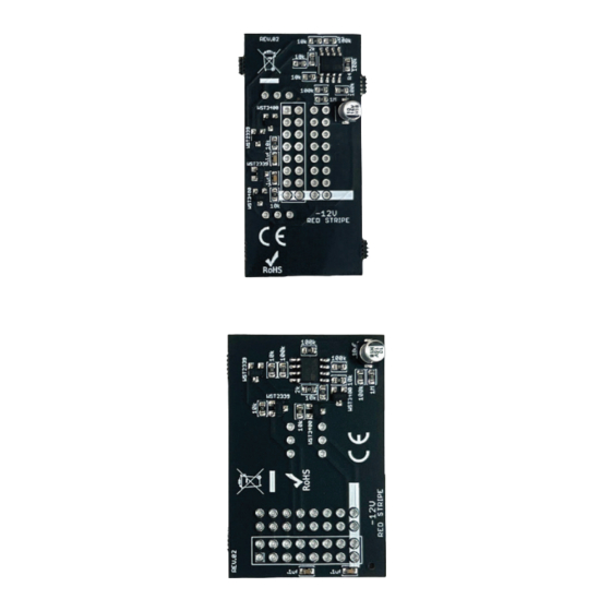
- Page 2 ADDAC900PD Assembly Guide February.2023 ADDAC SYSTEM page 2...
- Page 3 ADDAC900PD Assembly Guide STEP 1: Start by placing and solder the 90 degree 1x3 pinheaders STEP 2: Locate the 2x10 pinheader and using pliers pull the 4 legs at both edges like shown below. As we use Boxed Headers in all our Busboards the extra length of this connector will prevent an offsetted connection that could cause a short circuit in the psu.
- Page 4 ADDAC900PD Assembly Guide STEP 3: Place and solder the 2x8 modified pinheader. ADDAC SYSTEM page 4...
- Page 5 ADDAC900PD Assembly Guide STEP 4: Place and solder the 2x8 boxed pinheader like shown below, notice the indent orientation. STEP 5: Finish by placing the jumpers as you please. ADDAC SYSTEM page 5...
- Page 6 ADDAC900PD Assembly Guide You’re all done! Happy patching! ADDAC SYSTEM page 6...
- Page 7 For feedback, comments or problems please contact us at: addac@addacsystem.com ADDAC900PD ASSEMBLY GUIDE Revision.01 February.2023...
Need help?
Do you have a question about the ADDAC900PD and is the answer not in the manual?
Questions and answers