
Related Manuals for ADDAC System ADDAC714


Summary of Contents for ADDAC System ADDAC714
- Page 2 ADDAC714 Assembly Guide February.2023 ADDAC SYSTEM page 2...
- Page 3 ADDAC714 Assembly Guide STEP 1: Start by placing the diodes, notice the orientation marked on the pcb. STEP 2: Place and solder the 2x5 boxed pinheader. Notice the indent orientation. ADDAC SYSTEM page 3...
- Page 4 ADDAC714 Assembly Guide STEP 3: Next we’ll need to prepare some parts before placing them to the front panel. Use pliers to flatten out 2 of the pots legs like shown below STEP 4: Locate the jacks and cut the thinest leg like shown below.
- Page 5 ADDAC714 Assembly Guide STEP 5: Place and all parts on the pcb, notice the difference between the jacks. Once placed allign with the frontpanel and tighten all the nuts. Non-threaded Jacks Threaded Jacks Non-threaded Jacks Threaded Jacks ADDAC SYSTEM page 5...
- Page 6 ADDAC714 Assembly Guide STEP 6: Adjust the height of the pcb keeping it parallel to the front panel and proceed to solder all parts. Keep lines parallel ADDAC SYSTEM page 6...
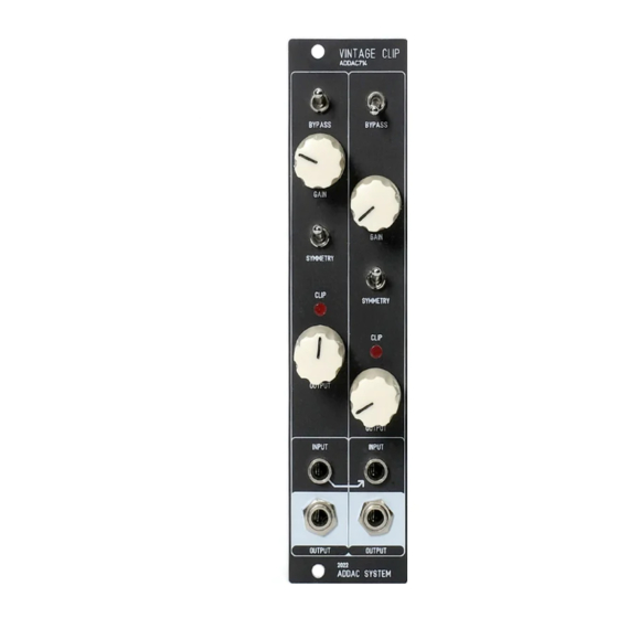
- Page 7 ADDAC714 Assembly Guide Finish it by placing the knobs and you’ve finished the assembly process! You’re all done! Happy patching! ADDAC SYSTEM page 7...
-
Page 8: Assembly Guide
For feedback, comments or problems please contact us at: addac@addacsystem.com ADDAC714 ASSEMBLY GUIDE Revision.01 February.2023...
Need help?
Do you have a question about the ADDAC714 and is the answer not in the manual?
Questions and answers