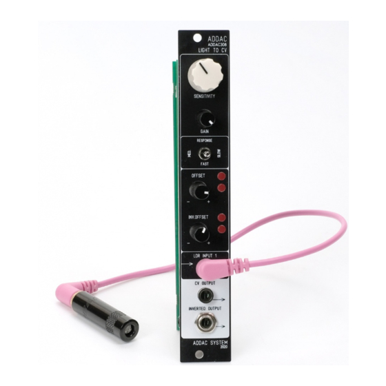
Summary of Contents for ADDAC System ADDAC308
- Page 2 ADDAC308 Assembly Guide June.2021 ADDAC SYSTEM page 2...
- Page 3 ADDAC308 Assembly Guide STEP 1: Place and solder the 78L05 voltage regulator STEP 2: Place and solder the 2x1 pinheaders STEP 3: Place and solder the power connector, notice the indentation below ADDAC SYSTEM page 3...
- Page 4 ADDAC308 Assembly Guide STEP 4: Place the spacer on the front pcb STEP 5: Attach both pcbs and solder the other end of the pinheaders to the bottom pcb ADDAC SYSTEM page 4...
- Page 5 ADDAC308 Assembly Guide STEP 6: Next we’ll need to prepare some parts before adding them to the front panel. Locate the jacks and cut the smallest legs like shown below. STEP 7: Next cut the top flange of the metal shaft potentiometer...
- Page 6 ADDAC308 Assembly Guide STEP 9: Next place the front panel and tighten both nuts STEP 10: Solder all the parts STEP 11: Place the bottom screw ADDAC SYSTEM page 6...
- Page 7 ADDAC308 Assembly Guide STEP 12: Now we’ll assemble the light sensor STEP 13: Cut the light sensor legs to 12mm and 15mm (there’s no polarity on the light sensor) 12mm 15mm ADDAC SYSTEM page 7...
- Page 8 ADDAC308 Assembly Guide STEP 14: Tin the jack socket on its ground leg and the round termination, ignore the square termination STEP 15: Solder the light sensor to the jack socket Make sure the long ground leg flaps touch the second light sensor leg...
- Page 9 ADDAC308 Assembly Guide Finish it by placing the knob and you’ve finished the assembly process! Happy patching! ADDAC SYSTEM page 9...
-
Page 10: Assembly Guide
For feedback, comments or problems please contact us at: addac@addacsystem.com ADDAC308 ASSEMBLY GUIDE Revision.01 June.2021...


Need help?
Do you have a question about the ADDAC308 and is the answer not in the manual?
Questions and answers