Advertisement
Quick Links
Advertisement

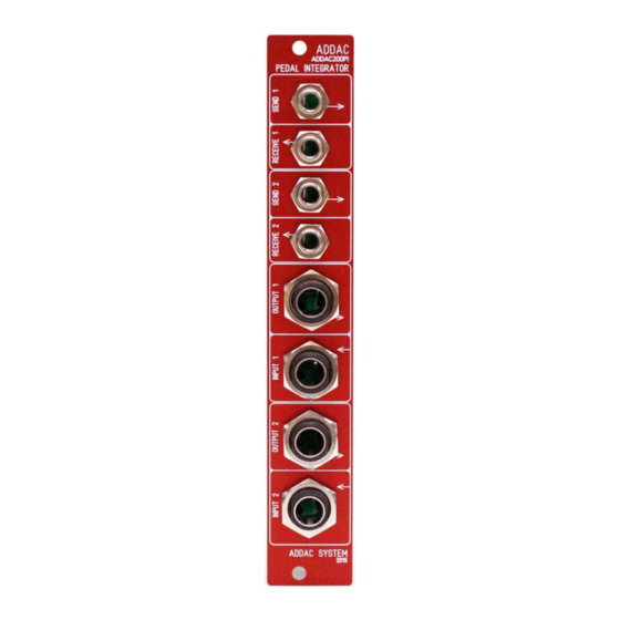
Summary of Contents for ADDAC System ADDAC200PI
- Page 1 All manuals and user guides at all-guides.com...
- Page 2 All manuals and user guides at all-guides.com ADDAC200PI Assembly Guide July.2019 ADDAC SYSTEM page 2...
- Page 3 All manuals and user guides at all-guides.com ADDAC200PI Assembly Guide STEP 1: Locate and solder the 4 capacitors like shown below.. ADDAC SYSTEM page 3...
- Page 4 All manuals and user guides at all-guides.com ADDAC200PI Assembly Guide STEP 3: Locate and solder the 2x5 boxed pinheader like shown below. ADDAC SYSTEM page 4...
- Page 5 All manuals and user guides at all-guides.com ADDAC200PI Assembly Guide STEP 6: Locate the remaining pinheaders, place and solder them like shown below. ADDAC SYSTEM page 5...
- Page 6 All manuals and user guides at all-guides.com ADDAC200PI Assembly Guide STEP 8: Locate all jacks and place them like shown below. ADDAC SYSTEM page 6...
- Page 7 All manuals and user guides at all-guides.com ADDAC200PI Assembly Guide STEP 11: Place the smaller pcb on the panel, tighten the nuts and solder their pads. ADDAC SYSTEM page 7...
- Page 8 All manuals and user guides at all-guides.com ADDAC200PI Assembly Guide STEP 13: Attach the bigger pcb tighten the nuts and solder the last pads. ADDAC SYSTEM page 8...
- Page 9 All manuals and user guides at all-guides.com ADDAC200PI Assembly Guide Congratulations you’re done! Happy Patching!! ADDAC SYSTEM page 15...
-
Page 10: Assembly Guide
All manuals and user guides at all-guides.com For feedback, comments or problems please contact us at: addac@addacsystem.com ADDAC200PI ASSEMBLY GUIDE Revision.01 July.2019...


Need help?
Do you have a question about the ADDAC200PI and is the answer not in the manual?
Questions and answers