
Related Manuals for ADDAC System T-Networks ADDAC103


Summary of Contents for ADDAC System T-Networks ADDAC103
- Page 2 ADDAC103 Assembly Guide July.2019 Tools Needed: Wire cutter Pliers ADDAC SYSTEM page 2...
- Page 3 ADDAC103 Assembly Guide STEP 1: Start by locating the 2x5 pinheader and the 78L05 regulator and solder them like shown below. ADDAC SYSTEM page 3...
- Page 4 ADDAC103 Assembly Guide STEP 2: Next locate the 2 capacitors and solder like shown below. ADDAC SYSTEM page 4...
- Page 5 STEP 4: For these 2 pots, trim the middle legs like shown below. STEP 5: Locate the plastic shaft trim pots and flatten out their legs with the help of some pliers, like shown below. ADDAC SYSTEM page 5...
- Page 6 ADDAC103 Assembly Guide STEP 6: After all parts are in position place the front panel and tighten the nuts like shown below. ADDAC SYSTEM page 6...
- Page 7 ADDAC103 Assembly Guide STEP 7: Solder all the front parts pads. ADDAC SYSTEM page 7...
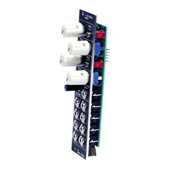
- Page 8 ADDAC103 Assembly Guide Finish it by placing the knobs and the remaining nuts and you’re done! Happy Patching!! ADDAC SYSTEM page 8...
-
Page 9: Assembly Guide
For feedback, comments or problems please contact us at: addac@addacsystem.com ADDAC103 ASSEMBLY GUIDE Revision.01 July.2019...
Need help?
Do you have a question about the T-Networks ADDAC103 and is the answer not in the manual?
Questions and answers