Table of Contents
Advertisement
Quick Links
Volvo vehicles with Sensus Connect Infotainment and internet button
Product features
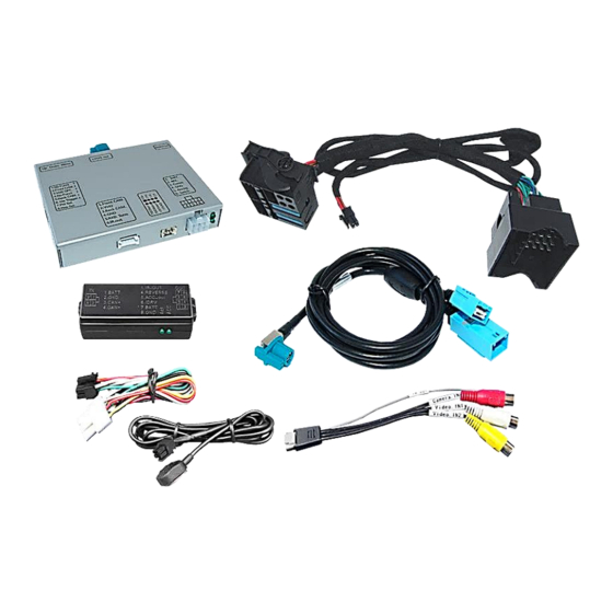
Video-inserter for factory-infotainment systems
2 CVBS video-inputs for after-market devices (e.g. DVD-Player, DVB-T tuner)
FBAS Rear-view camera video-input
Automatic switching to rear-view camera input on engagement of the reverse gear
Activatable parking guide lines for rear-view camera (not for all vehicles)
Picture-in-picture (PIP) mode combining after-market rear-view camera picture
with factory parking sensor graphic (not for all vehicles)
Video-in-motion in drive mode (ONLY for connected video-sources)
Video-inputs NTSC and PAL compatible
Version 09.03.2020
All manuals and user guides at all-guides.com
r.LiNK Video-inserter
RL2-SC14
Compatible with
with 7 inch monitor
Video-inserter for rear-view camera
and two additional video sources
CAM(V31)9275&9276(V11)
RL2-SC14
Advertisement
Table of Contents

Related Manuals for NavLinkz r.LiNK RL2-SC14


Summary of Contents for NavLinkz r.LiNK RL2-SC14
- Page 1 All manuals and user guides at all-guides.com r.LiNK Video-inserter RL2-SC14 Compatible with Volvo vehicles with Sensus Connect Infotainment and internet button with 7 inch monitor Video-inserter for rear-view camera and two additional video sources Product features Video-inserter for factory-infotainment systems ...
-
Page 2: Table Of Contents
All manuals and user guides at all-guides.com Contents 1. Prior to installation 1.1. Delivery contents 1.2. Checking the compatibility of vehicle and accessories 1.3. Connectors – video interface 1.4. Dip-switch settings 1.4.1. Enabling the interface’s video inputs (dip 2-3) 1.4.2. Rear-view camera setting (dip 5) 1.4.3. -
Page 3: Prior To Installation
All manuals and user guides at all-guides.com Legal Information By law, watching moving pictures while driving is prohibited, the driver must not be distracted. We do not accept any liability for material damage or personal injury resulting, directly or indirectly, from installation or operation of this product. This product should only be used while standing or to display fixed menus or rear-view-camera video when the vehicle is moving, for example the MP3 menu for DVD upgrades. -
Page 4: Checking The Compatibility Of Vehicle And Accessories
All manuals and user guides at all-guides.com 1.2. Checking the compatibility of vehicle and accessories Requirements Brand Compatible vehicles Compatible systems Sensus Connect with 7 inch monitor and Volvo Vehicles since model year 2014 internet button. Limitations Video only The interface inserts ONLY video signals into the infotainment. For inserting Audio signals either the possibly existing factory audio-AUX-input or a FM- modulator can be used. -
Page 5: Connectors - Video Interface
All manuals and user guides at all-guides.com 1.3. Connectors – video interface The video-interface converts the video signals of connected after-market sources in a factory monitor compatible picture signal which is inserted in the factory monitor, by using separate trigger options. 1.4. -
Page 6: Enabling The Interface's Video Inputs (Dip 2-3)
All manuals and user guides at all-guides.com 1.4.1.1. Enabling the interface’s video inputs (dip 2-3) Only the enabled video inputs can be accessed when switching through the interface’s video sources. It is recommended to enable only the required inputs for the disabled will be skipped when switching through the video-interfaces inputs. -
Page 7: Connection Schema
All manuals and user guides at all-guides.com 2.2. Connection schema Version 09.03.2020 CAM(V31)9275&9276(V11) RL2-SC14... -
Page 8: Connecting - Pnp Power / Can Cable
All manuals and user guides at all-guides.com 2.3. Connection - PNP Power / CAN cable Connect the female 10pin connector of the 10pin Power / CAN cable to the 10pin connector of the video interface. Remove the female 16pin Quadlock connector of the vehicle harness from the rear-side of the head-unit, clip-out chamber connectors A, B and the optical leads (see left picture and next page) and connect this Quadlock connector to the male 16pin Quadlock connector of the PNP Power / CAN cable. -
Page 9: Exchange Of Quadlock Chambers
All manuals and user guides at all-guides.com 2.3.1. Exchange of Quadlock chambers Version 09.03.2020 CAM(V31)9275&9276(V11) RL2-SC14... -
Page 10: Analogue Connecting - Video-Interface
All manuals and user guides at all-guides.com 2.4. Analogue connecting - video-interface If the communication between the CAN box and the vehicle’s CAN bus does not succeed (not all vehicles are compatible), an analogue connection is required by connecting the 6pin to 8pin cable without the CAN box. -
Page 11: Connection - Picture Signal Cable
All manuals and user guides at all-guides.com 2.5. Connection – picture signal cable Connect the waterblue colored female HSD+2pin connector of the picture signal cable to the male waterblue colored HSD+2pin connector on the rear-side of the interface. Remove the female lightblue colored 6pin connector from the rear-side of the head unit and connect it to the male lightblue colored 6pin connector of the picture signal cable. -
Page 12: Connecting Video Sources
All manuals and user guides at all-guides.com 2.6. Connecting video sources It is possible to connect one after-market rear-view camera and two more AV sources to the video-interface. Note: Before the final installation, we recommend a test-run to ensure the compatibility of the vehicle and the interface. -
Page 13: After-Market Rear-View Camera
All manuals and user guides at all-guides.com 2.6.1. After-market rear-view camera Some vehicles have a different reverse gear code on the CAN-bus which the included CAN- box is not compatible with. In this case there are two different ways of installation. If the CAN-box is able to detect an enabled vehicle’s reverse gear, the green wire of the 6pin to 8pin cable should carry +12V while the reverse gear is engaged. -
Page 14: Case 2: Can-Box Does Not Receive The Reverse Gear Signal
All manuals and user guides at all-guides.com 2.6.1.2. Case 2: CAN-box does not receive the reverse gear signal If the CAN-bus interface does not receive +12V on the green wire of the 6pin to 8pin cable when reverse gear is engaged (not all vehicles are compatible) an external switching signal from the reverse gear light is required. -
Page 15: Audio-Insertion
All manuals and user guides at all-guides.com 2.6.2. Audio Insertion This interface can only insert video signals into the factory infotainment. If an AV-source is connected, audio insertion must be done by factory audio AUX input or FM-modulator. The inserted video-signal can be activated simultaneously to each audio-mode of the factory infotainment. -
Page 16: Picture Settings And Guide Lines
All manuals and user guides at all-guides.com 2.8. Picture settings and guide lines The picture settings are adjusted by the 3 buttons on the video-interface. Press the MENU button to open the OSD settings menu or to switch to the next menu item. Press UP and DOWN change the selected value. -
Page 17: Interface Operation
All manuals and user guides at all-guides.com 3. Interface operation By infotainment button 3.1. Switching the video sources can be done by a long press of the vehicle’s „Exit“, „Navi“ or „Empty“ buttons. Each press (approx. 2 sec) will switch to the next enabled input. If all inputs are enabled the order is: ... -
Page 18: By External Keypad
All manuals and user guides at all-guides.com By external keypad 3.2. The interface’s keypad can be used to execute interface functions. Short press keypad to switch the video-source. Each repetition will switch to the next enabled input. Inputs which are not enabled are skipped. - Page 19 All manuals and user guides at all-guides.com FAQ – Trouble shooting Interface functions For any troubles which may occur, check the following table for a solution before requesting support from your vendor. Symptom Reason Possible solution Not all connectors have been reconnected to factory head- Connect missing connectors.
-
Page 20: Technical Support
6pin to 8pin cable and isolate both ends. Technical Support Please note that direct technical support is only available for products purchased directly from NavLinkz GmbH. For products bought from other sources, contact your vendor for technical support. NavLinkz GmbH...
Need help?
Do you have a question about the r.LiNK RL2-SC14 and is the answer not in the manual?
Questions and answers