
Related Manuals for Dell PowerEdge MX760c


Summary of Contents for Dell PowerEdge MX760c
- Page 1 Dell PowerEdge MX760c Installation and Service Manual Regulatory Model: E04B Regulatory Type: E04B004 February 2023 Rev. A01...
- Page 2 A WARNING indicates a potential for property damage, personal injury, or death. © 2021 - 2022 Dell Inc. or its subsidiaries. All rights reserved. Dell Technologies, Dell, and other trademarks are trademarks of Dell Inc. or its subsidiaries. Other trademarks may be trademarks of their respective owners.
-
Page 3: Table Of Contents
Contents Chapter 1: About this document....................7 Chapter 2: Dell PowerEdge MX760c system configurations and features........8 System configurations - front view for PowerEdge MX760c.................. 9 Left control panel view..............................11 System configurations - inside view for PowerEdge MX760c................12 Locating the Express Service Code and Service Tag....................14 System information label..............................15... - Page 4 Chapter 7: Installing and removing system components ............. 55 Safety instructions................................55 Before working inside your system ..........................56 After working inside your system..........................56 Recommended tools................................. 56 PowerEdge MX760c sled..............................56 Removing the sled from enclosure..........................56 Installing the sled into enclosure..........................58 Sled cover................................... 60 Removing the sled cover............................60 Installing the sled cover..............................
- Page 5 System memory................................. 93 System memory guidelines............................93 General memory module installation guidelines....................94 Removing a memory module.............................95 Installing a memory module............................96 Processor and heat sink module............................ 97 Removing a processor and heat sink module......................97 Removing the processor from the processor and heat sink module ............. 99 Installing the processor into a processor and heat sink module ..............
- Page 6 Chapter 11: Using system diagnostics..................150 Dell Embedded System Diagnostics..........................150 Running the Embedded System Diagnostics from Boot Manager..............150 Running the Embedded System Diagnostics from the Dell Lifecycle Controller........150 System diagnostic controls............................151 Chapter 12: Getting help......................152 Recycling or End-of-Life service information......................152 Contacting Dell Technologies............................
-
Page 7: Chapter 1: About This Document
About this document This document provides an overview about the system, information about installing and replacing components, diagnostic tools, and guidelines to be followed while installing certain components. About this document... -
Page 8: Chapter 2: Dell Poweredge Mx760C System Configurations And Features
● Up to 8 x E3.sNVMe (SSD) drives ● MX7000 Gold Grade (Hardware version 2, Gen2) fans NOTE: For more information about how to hot swap NVMe PCIe SSD U.2 device, see the Dell Express Flash NVMe PCIe SSD User's Guide at https://www.dell.com/support >... -
Page 9: System Configurations - Front View For Poweredge Mx760C
2. Drive blank 3. Drives 4. Release handle 5. Express service tag Figure 2. Front view of the 4 x 2.5-inch drive system with liquid cooling 1. Front I/O module 2. Liquid cooling tubes Dell PowerEdge MX760c system configurations and features... - Page 10 3. Release handle 4. Express service tag Figure 4. Front view of the 8 x E3.s drive system 1. Front I/O module 2. Drive blank 3. Express service tag 4. Drives 5. Release handle Dell PowerEdge MX760c system configurations and features...
-
Page 11: Left Control Panel View
2. Express service tag 3. Drives 4. Release handle 5. Liquid cooling tubes Left control panel view Figure 6. Front I/O module 1. iDRAC direct port 2. USB 3.0 port 3. Power button Dell PowerEdge MX760c system configurations and features... -
Page 12: System Configurations - Inside View For Poweredge Mx760C
6. Memory modules for Processor 2 7. Mezzanine card A 8. Mezzanine card B 9. Mini Mezzanine connector C 10. System board 11. BOSS-N1 (M.2) 12. PERC connector (H755 MX, H965i MX, HBA350i MX) Dell PowerEdge MX760c system configurations and features... - Page 13 1. Liquid cooling tubes 2. Drive cage 3. Backplane 4. Memory modules for Processor 1 5. Liquid cooling with Processor and heat sink module 1 and 2 6. Memory modules for v 2 Dell PowerEdge MX760c system configurations and features...
-
Page 14: Locating The Express Service Code And Service Tag
The Mini Enterprise Service Tag (MEST) label is located on the rear of the system that includes the Service Tag (ST), Express Service Code (Exp Svc Code), and Manufacture Date (Mfg. Date). The Exp Svc Code is used by Dell to route support calls to the appropriate personnel. -
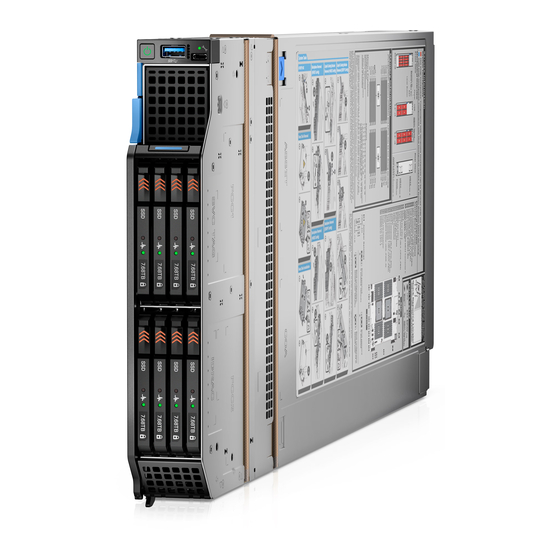
Page 15: System Information Label
System information label Figure 12. Mechanical overview Figure 13. Memory overview Dell PowerEdge MX760c system configurations and features... - Page 16 Figure 14. System board and jumper settings Figure 15. Quick Resource Locator Dell PowerEdge MX760c system configurations and features...
- Page 17 Figure 16. System tasks Dell PowerEdge MX760c system configurations and features...
-
Page 18: Chapter 3: Technical Specifications
• Video specifications • Environmental specifications Sled dimensions Figure 17. Sled dimensions Table 1. PowerEdge MX760c sled dimensions System configuration Z (handle closed). 4 x 2.5-inch or 6 x 2.5-inch 257.0 mm (10 inches) 51.0 mm (2 inches) 622.35 mm (24.5 inches) 8 x E3.s... -
Page 19: Sled Weight
● VMware vSAN/ESXi For more information, go to www.dell.com/ossupport. System battery specifications The PowerEdge MX760c system supports CR 2032 3.0-V lithium coin cell system battery. Memory specifications The PowerEdge MX760c system supports the following memory specifications for optimized operation. Table 4. Memory specifications... -
Page 20: Perc, Mezzanine And Mini Mezzanine Slots Specifications
● 6 x 2.5-inch hot-swappable SAS, SATA (HDD/SSD) drives on x6 SAS/SATA backplane configuration. ● 8 x E3.s hot-swappable NVMe SSD drives on E3x8 backplane configuration. NOTE: For more information about how to hot swap NVMe PCIe SSD U.2 device, see the Dell Express Flash NVMe PCIe SSD User's Guide at https://www.dell.com/support >... -
Page 21: Ports And Connectors Specifications
The micro USB 2.0 compliant port can only be used as an iDRAC Direct or a management port. Video specifications The PowerEdge MX760c system supports Matrox G200 W3 graphics controller integrated with iDRAC with 16 MB of video frame buffer. -
Page 22: Environmental Specifications
Environmental specifications NOTE: For additional information about environmental certifications, refer to the Product Environmental Datasheet located with the Documentation on www.dell.com/support/home. Table 9. Operational climatic range category A2 Temperature Specifications Allowable continuous operations Temperature ranges for altitudes <= 900 m (<= 10–35°C (50–95°F) with no direct sunlight on the equipment... -
Page 23: Thermal Restriction Matrix
Six consecutively executed shock pulses in the positive and negative x, y, and z axis (one pulse on each side of the system) of 71 G for up to 2 ms. Thermal restriction matrix Table 15. The PowerEdge MX760c thermal restriction matrix Configuration 6 x 2.5-inch BP 6 x 2.5-inch BP... - Page 24 ● With Air Cooling Solution, Higher wattage processors, Thermal Design Power (TDP) > 185 W are not supported. ● With Liquid Cooling Solution, all processors are supported. ● Non-Dell qualified peripheral cards or peripheral cards greater than 30 W are not supported. ● PCIe SSD is not supported.
- Page 25 ● Non-Dell qualified peripheral cards or peripheral cards greater than 30 W are not supported. ● PCIe SSD is not supported. ● 128 GB or higher capacity RDIMM is not supported. ● E3.s drive is not supported. Technical specifications...
-
Page 26: Chapter 4: Initial System Setup And Configuration
Initial system setup and configuration This section describes the tasks for initial setup and configuration of the Dell system. The section also provides general steps to set up the system and the reference guides for detailed information. Topics: • Setting up the system •... - Page 27 NOTE: When selecting or upgrading the system configuration, to ensure optimum power utilization, verify the system power consumption with the Enterprise Infrastructure Planning Tool available at Dell.com/calc. NOTE: To generate the thermally optimized sled-to-slot assignments, enter the MX configuration in the EIPT tool and click...
-
Page 28: Idrac Configuration
The Integrated Dell Remote Access Controller (iDRAC) is designed to make you more productive as a system administrator and improve the overall availability of Dell servers. iDRAC alerts you to system issues, helps you to perform remote management, and reduces the need for physical access to the system. -
Page 29: Options To Log In To Idrac
Table 17. Interfaces to set up iDRAC IP address Interface Documentation links iDRAC Settings utility Integrated Dell Remote Access Controller User's Guide at https://www.dell.com/idracmanuals or for system specific Integrated Dell Remote Access Controller User's Guide, go to https://www.dell.com/poweredgemanuals > Product Support page of your system >... -
Page 30: Resources To Install Operating System
Ensure that you change the default username and password after setting up the iDRAC IP address. For more information about logging in to the iDRAC and iDRAC licenses, see the latest Integrated Dell Remote Access Controller User's Guide at www.dell.com/idracmanuals. -
Page 31: Options To Download And Install Os Drivers
Ensure that you clear the web browser cache before downloading the drivers and firmware. Steps 1. Go to www.dell.com/support/drivers. 2. Enter the Service Tag of the system in the Enter a Dell Service Tag, Dell Product ID or Model field, and then press Enter. NOTE: If you do not have the Service Tag, click Browse all products, and navigate to your product. -
Page 32: Chapter 5: Pre-Operating System Management Applications
UEFI (Unified Extensible Firmware Interface). You can enable or disable various iDRAC parameters by using the iDRAC settings utility. For more information about this utility, see Integrated Dell Remote Access Controller User’s Guide at www.dell.com/ poweredgemanuals. -
Page 33: System Bios
Table 21. System Setup Main Menu (continued) Option Description Device Settings Enables you to configure device settings for devices such as storage controllers or network cards. Service Tag Settings Enables you to configure the System Service Tag. System BIOS To view the System BIOS screen, power on the system, press F2, and click System Setup Main Menu > System BIOS. Table 22. - Page 34 Table 23. System Information details (continued) Option Description System Manufacturer Specifies the name of the system manufacturer. System Manufacturer Contact Information Specifies the contact information of the system manufacturer. System CPLD Version Specifies the current version of the system Complex Programmable Logic Device (CPLD) firmware.
- Page 35 Table 24. Memory Settings details (continued) Option Description Memory Map Out This option controls DIMMs slots on the system. This option is set to Enabled by default. It allows to disable system installed DIMMs. Processor Settings To view the Processor Settings screen, power on the system, press F2, and click System Setup Main Menu > System BIOS >...
- Page 36 MADT Core Enumeration Specifies the MADT Core Enumeration. This option is set to default in Round Robin. Linear option supports industry core enumeration whereas, Round Robin option supports Dell optimized core enumeration. UPI Prefetch Enables you to get the memory read started early on DDR bus.
- Page 37 Enables you to configure the Dell AVX scaling technology. This option is set to 0 by default. Enter the value from 0 to 12 bins. The value that is entered decreases the Dell AVX Scaling Technology frequency when the Dell-controlled Turbo feature is enabled.
- Page 38 Table 25. Processor Settings details (continued) Option Description affected thread rather than broadcast to all threads in the system. The feature supports operating system recovery for cases of multiple recoverable faults that are detected close, which would otherwise result in a fatal machine check event. The feature is available only on Advanced RAS processors.
- Page 39 Enables or disables the boot mode. The option is set to Non-RAID mode by default. BIOS NVMe Driver Sets the drive type to boot the NVMe driver. The available options are Dell Qualified Drives and All Drives. This option is set to Dell Qualified Drives by default.
- Page 40 Operating systems must be UEFI-compatible to be installed from the UEFI boot mode. DOS and 32-bit operating systems do not support UEFI and can only be installed from the BIOS boot mode. NOTE: For the latest information about supported operating systems, go to www.dell.com/ossupport. Changing boot order About this task You may have to change the boot order if you want to boot from a USB key or an optical drive.
- Page 41 Domain Name>:<Unique String>. Leave it empty to use system generated value with following format: nqn.1988-11.com.dell:<Model name>.<Model number>.<Service Tag>. This is set to nqn.1988-11.com.dell:<model name>.<model number>.<service tag> by default. NVMe-oF Host Id This field specifies a 16 bytes value of the NVMe-oF host identifier that uniquely identifies this host with the controller in the NVM subsystem.
- Page 42 Table 34. NVMe-oF SubSystem Settings screen details Option Description NVMe-oF SubSystem n (n = 1 to 4) Enables or disables NVMe-oF SubSystem. This option is set to Disabled by default. NVMe-oF SubSystem n Settings (n = 1 Enables you to control the configuration of the NVMe-oF SubSystem, if Enabled. to 4) Table 35.
- Page 43 Integrated Devices To view the Integrated Devices screen, power on the system, press F2, and click System Setup Main Menu > System BIOS > Integrated Devices. Table 36. Integrated Devices details Option Description User Accessible USB Ports Configures the user accessible USB ports. Selecting All Ports Off (Dynamic) disables all front and back USB ports during POST.
- Page 44 To view the Serial Communication screen, power on the system, press F2, and click System Setup Main Menu > System BIOS > Serial Communication. NOTE: The serial port is optional for the PowerEdge MX760c system. The Serial Communication option is applicable only if the serial COM port is installed in the system. Table 37. Serial Communication details...
- Page 45 Table 37. Serial Communication details (continued) Option Description BIOS setup utility may not always revert the serial MUX setting to the default setting of Serial Device 1. External Serial Connector Enables you to associate the External Serial Connector to Serial Device 1 by using this option.
- Page 46 Table 38. System Profile Settings details (continued) Option Description Memory Refresh Rate Sets the memory refresh rate to either 1x or 2x. This option is set to 1x by default. Uncore Frequency Enables you to select the Uncore Frequency option. Dynamic mode enables the processor to optimize power resources across cores and uncores during runtime.
- Page 47 Table 40. TPM 2.0 security information (continued) Option Description When TPM 2.0 is installed, the TPM Security option is set to On or Off. This option is set to Off by default. TPM Information Indicates the type of Trusted Platform Module, if present. TPM Firmware Indicates the firmware version of the TPM.
- Page 48 Table 41. System Security details (continued) Option Description NOTE: BIOS update requires HECI devices to be operational and DUP updates require IPMI interface to be operational. This setting needs to be set to Enabled to avoid updating errors. SMM Security Migration Enables or disables the UEFI SMM security migration protections.
- Page 49 3. On the System Security screen, verify that Password Status is set to Unlocked. 4. In the System Password field, type your system password, and press Enter or Tab. Use the following guidelines to assign the system password: ● A password can have up to 32 characters. A message prompts you to reenter the system password.
- Page 50 Operating with setup password enabled If Setup Password is set to Enabled, type the correct setup password before modifying the system setup options. If you do not type the correct password in three attempts, the system displays the following message: Invalid Password! Number of unsuccessful password attempts: <x>...
-
Page 51: Idrac Settings
Dell Lifecycle Controller Dell Lifecycle Controller (LC) provides advanced embedded systems management capabilities including system deployment, configuration, update, maintenance, and diagnosis. LC is delivered as part of the iDRAC out-of-band solution and Dell system embedded Unified Extensible Firmware Interface (UEFI) applications. -
Page 52: Boot Manager
Launch System Setup Enables you to access System Setup. Launch Lifecycle Controller Exits the Boot Manager and invokes the Dell Lifecycle Controller program. System Utilities Enables you to launch System Utilities menu such as Launch Diagnostics, BIOS update File Explorer, Reboot System. -
Page 53: Chapter 6: Minimum To Post And System Management Configuration Validation
Minimum to POST and system management configuration validation This section describes the minimum to POST system requirement and system management configuration validation of the Dell system. Topics: • Minimum configuration to POST • Configuration validation Minimum configuration to POST The components listed below are the minimum configuration to POST: ●... -
Page 54: Error Messages
Table 45. Configuration validation error (continued) Error Description Possible cause and Example recommendations Comm Error A configuration element is not responding System management Comm Error: Backplane 2 to iDRAC using the management interface sideband communication while running an inventory check. Unplug AC Power, reseat the element and replace the element if the problem... -
Page 55: Chapter 7: Installing And Removing System Components
Damage due to servicing that is not authorized by Dell is not covered by your warranty. Read and follow the safety instructions that are shipped with your product. -
Page 56: Before Working Inside Your System
NOTE: Use alpha wire part number 3080 or equivalent (65/30 stranding). PowerEdge MX760c sled The PowerEdge MX760c sled is a server unit that is installed into the PowerEdge MX7000 enclosure. Removing the sled from enclosure Prerequisites 1. Follow the safety guidelines listed in Safety instructions. - Page 57 Steps 1. Press the blue release button on the sled to release the sled handle. 2. Holding the sled handle, slide the sled out of the enclosure. NOTE: Support the system with both hands while sliding it out of the enclosure. NOTE: Removing the sled with the enclosure powered on is supported if you shut down the sled before removal.
-
Page 58: Installing The Sled Into Enclosure
Figure 19. Installing the I/O connector cover on sled NOTE: The color of the I/O connector cover may differ. CAUTION: If you are permanently removing the sled, install a sled blank promptly. Operating the enclosure without a blank, for an extended time can result in overheating or performance loss. Next steps Installing the sled into enclosure. - Page 59 Figure 20. Removing the I/O connector cover from sled NOTE: The color of the I/O connector cover may differ. 2. Press the blue release button on the sled to release the sled handle. 3. Holding the sled with both hands, align the sled with the compute sled-bay in the enclosure. 4.
-
Page 60: Sled Cover
Figure 21. Installing the sled into enclosure Next steps 1. Power on the sled. Sled cover Removing the sled cover Prerequisites 1. Follow the safety guidelines listed in the Safety instructions. 2. Power off the sled. Remove the sled from the enclosure. -
Page 61: Installing The Sled Cover
Figure 22. Removing the sled cover Next steps Installing the sled cover. Installing the sled cover Prerequisites 1. Follow the safety guidelines listed in the Safety instructions. 2. Ensure that all internal cables are connected and routed properly, and no tools or extra parts are left inside the system. Steps 1. - Page 62 Figure 23. Installing the sled cover Next steps 1. Follow the procedure listed in After working inside your system. Installing and removing system components...
-
Page 63: Air Shroud
Air shroud Removing the air shroud Prerequisites CAUTION: Never operate your system with the air shroud removed. The system may get overheated quickly, resulting in shutdown of the system and loss of data. 1. Follow the safety guidelines listed in the Safety instructions. - Page 64 Figure 25. Installing the air shroud Next steps 1. Follow the procedure listed in After working inside your system. Installing and removing system components...
-
Page 65: Processor And Memory Module Blank
Processor and memory module blank Removing the processor and memory module blank Prerequisites 1. Follow the safety guidelines listed in the Safety instructions. 2. Follow the procedure listed in Before working inside your system. Steps 1. To release the processor and memory module blank from the socket, simultaneously press the ejectors on both ends of the memory module socket to fully open. -
Page 66: Drives
Figure 27. Installing the processor and memory module blank 2. Align the edges of the processor and memory module blank with the alignment key of the memory module socket, and insert the blank in the socket. 3. Press the blank with your thumbs until the ejectors firmly click into place. Next steps 1. -
Page 67: Installing A Drive Blank
Figure 28. Removing drive blank Next steps Install a drive carrier installing a drive blank. Installing a drive blank Prerequisites 1. Follow the safety guidelines listed in the Safety instructions. Steps Insert the drive blank into the drive slot until the release button clicks into place. Figure 29. -
Page 68: Installing An E3.S Drive Blank
Steps Press the release button and slide the drive blank out of the drive slot. Figure 30. Removing an E3.s drive blank Next steps Replace the E3.s drive blank. Installing an E3.s drive blank Prerequisites 1. Follow the safety guidelines listed in the Safety instructions. -
Page 69: Removing The Drive Carrier
Removing the drive carrier Prerequisites 1. Follow the safety guidelines listed in the Safety instructions. 2. Using the management software, prepare the drive for removal. If the drive is online, the green activity or fault indicator blinks while the drive is powering off. When the drive indicators are off, the drive is ready for removal. For more information, see the documentation for the storage controller. -
Page 70: Removing The E3.S Drive Carrier
CAUTION: When installing a drive, ensure that the adjacent drives are fully installed. Inserting a drive carrier and attempting to lock its handle next to a partially installed carrier can damage the partially installed carrier's shield spring and make it unusable. CAUTION: To prevent data loss, ensure that your operating system supports hot-swap drive installation. -
Page 71: Installing The E3.S Drive Carrier
Figure 34. Removing the E3.s drive carrier Next steps Installing the E3.s drive carrier Installing the E3.s drive carrier Prerequisites CAUTION: Before removing or installing a drive while the system is running, see the documentation for the storage controller card to ensure that the host adapter is configured correctly to support drive removal and insertion. -
Page 72: Removing The Drive From The Drive Carrier
Figure 35. Installing the E3.s drive carrier Removing the drive from the drive carrier Prerequisites 1. Follow the safety guidelines listed in the Safety instructions remove a drive carrier Steps 1. Using the Phillips #1 screwdriver, remove the screws from the slide rails on the drive carrier. NOTE: If the hard drive or SSD carrier has Torx screw, use Torx 6 (for 2.5-inch drive) or Torx 8 (for 3.5-inch drive) screwdriver to remove the drive. -
Page 73: Installing The Drive Into The Drive Carrier
Figure 37. Removing a SSD from drive carrier Next steps install the drive into drive carrier. Installing the drive into the drive carrier Prerequisites 1. Follow the safety guidelines listed in the Safety instructions. remove a drive carrier. NOTE: When installing a drive into the drive carrier, ensure that the screws are torqued to 4 in-lbs. Steps 1. -
Page 74: Removing The E3.S Drive From The Drive Carrier
Figure 38. Installing a drive into drive carrier Figure 39. Installing a SSD into drive carrier Next steps install the drive carrier. Removing the E3.s drive from the drive carrier Prerequisites 1. Follow the safety guidelines listed in the Safety instructions. -
Page 75: Installing The E3.S Drive Into The Drive Carrier
If the drive is online, the green activity or fault indicator blinks while the drive is powering off. When the drive indicators are off, the drive is ready for removal. For more information, see the documentation for the storage controller. CAUTION: Before attempting to remove or install a drive while the system is running, see the documentation for the storage controller card to ensure that the host adapter is configured correctly to support drive... -
Page 76: Drive Backplane
Steps 1. Insert the drive into the drive carrier with the drive connector facing towards the rear of the carrier. 2. Align the screw holes on the drive with the screws holes on the drive carrier. 3. Using a Phillips 1 screwdriver, secure the drive to the drive carrier with the screws. NOTE: When installing a drive into the drive carrier, ensure that the screws are torqued to 4 lbf-in. - Page 77 Figure 42. 6 x 2.5-inch SAS/SATA backplane 1. BP_DST_PA2 (PCIe cable connector) 2. BP_DST_PB1 (PCIe cable connector) 3. BP_DST_SA1 (SAS/SATA cable connector) 4. BP_PWR_1 (Power cable connector) 5. BP_DST_PA1 (PCIe cable connector ) Figure 43. 6 x 2.5-inch universal backplane 1.
-
Page 78: Removing Drive Backplane
Figure 45. 8 x E3.s backplane 1. BP_DST_PA2 (PCIe cable connector) 2. BP_DST_PB1 (PCIe cable connector) 3. BP_DST_PB2 (PCIe cable connector) 4. BP_PWR_1 (Power cable connector) 5. BP_DST_PA1 (PCIe cable connector ) Removing drive backplane Prerequisites CAUTION: To prevent damage to the drives and backplane, remove the drives from the system before removing the backplane. -
Page 79: Installing Drive Backplane
Figure 46. Removing the drive backplane Next steps Replace the drive backplane Installing drive backplane Prerequisites 1. Follow the safety guidelines listed in the Safety instructions. 2. Follow the procedure listed in Before working inside your system. Remove all the drives. -
Page 80: Drive Cage
Figure 47. Installing the drive backplane Next steps 1. Connect the incoming power cable to the backplane and then verify both power and signal cable connections are fully seated to the backplane and system board. 2. Connect the integrated cable to the backplane and system board if there is no PERC card installed in the system. Install all drives. - Page 81 Steps 1. Using the Phillips #1 screwdriver, remove the screws that secure the drive cage to the sled. 2. Lift the drive cage away from the sled. Figure 48. Removing the drive cage of 6 x 2.5-inch drive sled Figure 49. Removing the drive cage of 8 x E.3s inch drive sled Installing and removing system components...
-
Page 82: Installing The Drive Cage
Next steps Install the drive cage. Installing the drive cage Prerequisites 1. Follow the safety guidelines listed in the Safety instructions. 2. Follow the procedure listed in Before working inside your system. 3. Disconnect the drive backplane cables from the connectors on the system board. Steps 1. -
Page 83: Cable Routing
Figure 51. Installing the drive cage of 8 x E3.s drive sled Next steps Install the drive backplane. Install all drives. 3. Follow the procedure listed in After working inside your system. . Cable routing Figure 52. SAS/SATA/NVMe cabling diagram of configuration 0 - 6 x 2.5-inch universal backplane Installing and removing system components... - Page 84 Table 48. Connector descriptions for SATA/NVMe From BP_PWR_1 (backplane power connector) SIG_PWR_0 (system board power connector) BP_DST_SA1 (backplane SATA connector) SL3_PCH_SA1 (signal connector on the system board) BP_DST_PA1(backplane PCIe cable connector) SL1_CPU1_PB2 (signal connector on the system board) BP_DST_PB1 (backplane PCIe cable connector) SL2_CPU1_PA2 (signal connector on the system board) BP_DST_PA2 (backplane PCIe cable connector) SL4_CPU2_PB3 (signal connector on the system board)
- Page 85 Figure 54. NVMe RAID cabling diagram of configuration 2 - 6 x 2.5-inch universal backplane with H755 MX or H965i Table 50. Connector descriptions for NVMe with H755 MX or H965i MX From BP_PWR_1 (backplane power connector) SIG_PWR_0 (system board power connector) BP_DST_PA1(backplane PCIe cable connector) CTRL_SRC_PA1 (PCIe connector of H755 MX or H965i MX controller card, cable marking CTRL_PA1)
- Page 86 Table 51. Connector descriptions for SATA From BP_PWR_1 (backplane power connector) SIG_PWR_0 (system board power connector) BP_DST_SA1 (backplane SATA connector) SL3_PCH_SA1 (signal connector on the system board) Figure 56. SAS/SATA cabling diagram of configuration 4 - 6 x 2.5-inch SAS/SATA backplane with HBA350i MX Table 52.
- Page 87 Table 53. Connector descriptions for SAS with H755 MX or H965i MX From BP_PWR_1 (backplane power connector) SIG_PWR_0 (system board power connector) BP_DST_SA1 (backplane SAS/SATA connector) CTRL_SRC_SA1 (H755 MX or H965i MX controller connector on the system board) Figure 58. SATA//SAS/NVMe cabling diagram of configuration 7 - 4 x 2.5-inch universal backplane with HBA350i Table 54.
- Page 88 Figure 59. SAS/SATA/NVMe cabling diagram of configuration 8- 4 x 2.5-inch universal backplane with H755 MX or H965i MX Table 55. Connector descriptions for NVMe with H755 MX or H965i MX From BP_PWR_1 (backplane power connector) SIG_PWR_0 (system board power connector) BP_DST_PA1(backplane PCIe cable connector) SL1_CPU1_PB2 (signal connector on the system board) BP_DST_PB1 (backplane PCIe cable connector)
- Page 89 Figure 61. NVMe RAID cabling diagram of configuration 11- 4 x 2.5-inch universal backplane with H755 MX or H965i Table 57. Connector descriptions for NVMe with H755 MX or H965i MX From BP_PWR_1 (backplane power connector) SIG_PWR_0 (system board power connector) BP_DST_PA1(backplane PCIe cable connector) CTRL_SRC_PA1 (PCIe connector of H755 MX or H965i MX controller card, cable marking CTRL_PA1)
- Page 90 Table 58. Connector descriptions for SATA (continued) From BP_DST_SA1 (backplane SATA connector) SL3_PCH_SA1 (signal connector on the system board) Figure 63. NVMe cabling diagram of configuration 13 - 8 x E3.s backplane Table 59. Connector descriptions for NVMe From BP_PWR_1 (backplane power connector) SIG_PWR_0 (system board power connector) BP_DST_PA1 (PCIe cable connector ) SL1_CPU1_PB2(signal connector on the system board)
-
Page 91: Front I/O Module
Table 60. Connector descriptions for NVMe with H755 MX or H965i MX From BP_PWR_1 (backplane power connector) SIG_PWR_0 (system board power connector) BP_DST_PA1 (PCIe cable connector ) CTRL_SRC_PA1 (PCIe connector of H755 MX or H965i MX controller card, cable marking CTRL_PA1) BP_DST_PB1 (PCIe cable connector) CTRL_SRC_PA1 (PCIe connector of H755 MX or H965i MX controller card, cable marking CTRL_PA1) -
Page 92: Installing The Front I/O Module
Figure 65. Removing the front I/O module Next steps Replace the front I/O module. Installing the front I/O module Prerequisites 1. Follow the safety guidelines listed in the Safety instructions. 2. Follow the procedure listed in Before working inside your system. -
Page 93: System Memory
System memory System memory guidelines The PowerEdge MX760c system supports DDR5 registered DIMMs (RDIMMs).System memory holds the instructions that are executed by the processor. Your system contains 32 memory sockets that are split into two sets of 16 sockets, one set per processor. Each 16-socket set is organized into eight channels. -
Page 94: General Memory Module Installation Guidelines
Figure 67. Memory sockets on the system board NOTE: When High Performance CPU is installed, DIMM 9, 10,11,12 are not supported The following table shows the memory populations and operating frequencies for the supported configurations: Table 62. Supported memory matrix DIMM Type DIMM Ranking Capacity... -
Page 95: Removing A Memory Module
● Maximum supported speed of the DIMMs NOTE: MT/s indicates DIMM speed in MegaTransfers per second. The system supports Flexible Memory Configuration, enabling the system to be configured and run in any valid chipset architectural configuration. The following are the recommended guidelines for installing memory modules: ●... -
Page 96: Installing A Memory Module
CAUTION: Handle each memory module only by the card edges, ensuring not to touch the middle of the memory module or metallic contacts. 2. To release the memory module from the socket, simultaneously press the ejectors on both ends of the memory module socket to fully open. -
Page 97: Processor And Heat Sink Module
NOTE: The memory module socket has an alignment key that enables you to install the memory module in the socket in only one orientation. CAUTION: Do not apply pressure at the center of the memory module; apply pressure at both ends of the memory module evenly. - Page 98 Steps 1. Ensure all four anti-tilt wires are in the locked position (outward position), and then using a Torx T30 tool, loosen the captive nuts on the heat sink in the order that is mentioned below: a. Loosen the first nut three turns. b.
-
Page 99: Removing The Processor From The Processor And Heat Sink Module
Figure 71. Removing a processor and heat sink module Next steps Remove the processor from the processor and heat sink module. Removing the processor from the processor and heat sink module Prerequisites WARNING: Remove the processor from the processor and heat sink module (PHM) only if you are replacing the processor or heat sink. - Page 100 3. Holding the processor by its edges, lift the processor away from the retaining clip, and then place the processor connector side down on the processor tray. Ensure pin 1 marks are aligned. Figure 72. Lift up the TIM break lever Figure 73.
-
Page 101: Installing The Processor Into A Processor And Heat Sink Module
Figure 74. Removing the processor retaining clip Next steps Replace the processor into a processor and heat sink module (PHM). Installing the processor into a processor and heat sink module Prerequisites 1. Follow the safety guidelines listed in the Safety instructions. - Page 102 Figure 75. Installing the processor carrier 3. Align the processor with processor retaining clip by using your fingers to press the retaining clip on all the four sides until it clicks into place. NOTE: Ensure that the processor is securely latched to the processor retaining clip. Figure 76.
- Page 103 Figure 77. Applying thermal grease CAUTION: Applying too much thermal grease can result in excess grease coming in contact with and contaminating the processor socket. NOTE: The thermal grease syringe is intended for single use only. Dispose of the syringe after you use it. 6.
-
Page 104: Installing The Processor And Heat Sink Module
NOTE: Ensure latching features on processor retaining clip and heat sink are aligned during assembly. Figure 79. Installing the heat sink onto the processor Next steps Install the processor and heat sink module. Install the air shroud. 3. Follow the procedure listed in After working inside your system. - Page 105 NOTE: Ensure that the processor and heat sink is held parallel to the system board to prevent damaging the components. Figure 80. Installing the processor and heat sink (PHM) 3. Set the anti-tilt wires to the locked position (outward position), and then using the Torx T30 tool, tighten the captive nuts (8 in-lbf) on the heat sink in the order below: a.
- Page 106 Figure 81. Set the anti-tilt wires to the locked position and tightening the captive nuts Next steps Install the air shroud. 2. Follow the procedure listed in After working inside your system. Installing and removing system components...
-
Page 107: Liquid Cooling
Liquid cooling Removing the x4 2.5-inch and x8 E3.s liquid cooling assembly Steps 1. Disconnect the leak sensor cable from the system board. Figure 82. Removing the x4 2.5-inch liquid cooling assembly Installing and removing system components... -
Page 108: Removing The Processor From The Cold Plate
Figure 83. Removing the x8 E3.s liquid cooling assembly 2. For x4 2.5-inch liquid cooling assembly, pull the metal latch to release the latch and then push the guide feature to remove the liquid cooling cage. For x8 E3.s liquid cooling assembly, release one screw on hard drive cage to remove the liquid cooling cage. - Page 109 Steps 1. Start with the cold plate assembly lying on the ESD surface with their processor side facing up. 2. Lift up the Thermal Interface Material (TIM) break lever to release the processor from the TIM and retaining clip. NOTE: Ensure to hold the retaining clip to the cold plate as you lift the TIM break lever.
- Page 110 Figure 85. Aligning pin 1 marks of processor with tray NOTE: Ensure that to return the TIM break lever back to its original position. 4. To remove the plastic retainer from the cold plate, first hold the retaining clip release tab at the pin 1 connector, pull out the tip of the retaining clip release tab, and then lift the retaining clip partially from the cold plate.
-
Page 111: Installing The Processor Into A Liquid Cooling Cold Plate
Figure 86. Removing the processor retaining clip Installing the processor into a liquid cooling cold plate Prerequisites 1. Follow the safety guidelines listed in the Safety instructions. 2. Follow the procedure listed in Before working inside your system. NOTE: The CPU assembly orientation between CPU 1 and CPU2 is reverse. Steps 1. - Page 112 Figure 87. Installing the processor retaining clip 3. Align the processor with processor retaining clip by using your fingers to press the retaining clip on all the four sides until it clicks into place. NOTE: Ensure that the processor is securely latched to the processor retaining clip. Figure 88.
- Page 113 Figure 89. Applying thermal grease CAUTION: Applying too much thermal grease can result in excess grease coming in contact with and contaminating the processor socket. NOTE: The thermal grease syringe is intended for single use only. Dispose of the syringe after you use it. 6.
-
Page 114: Installing A X4 2.5-Inch And X8 E3.S Liquid Cooling Assembly
NOTE: Ensure that the pin 1 indicator on the cold plate is aligned with the pin 1 indicator on the retaining clip before placing the cold plate onto the processor retaining clip. NOTE: Ensure latching features on processor retaining clip and cold plate are aligned during assembly. Figure 91. - Page 115 Figure 92. Installing the processor and liquid cooling cold plate 3. Set the Anti-Tilt wires to the locked position (outward position), and then using the Torx #T30 screwdriver, tighten the screws on each cold plate, one at a time, in the order below: a.
- Page 116 Figure 93. Installing a x4 2.5-inch liquid cooling assembly NOTE: It is critical to ensure the sensor cable is connected. Installing and removing system components...
-
Page 117: Perc Card
Figure 94. Installing a x8 E3.s liquid cooling assembly PERC card Your system includes dedicated slots on the system board for PERC cards. Removing the PERC card Prerequisites 1. Follow the safety guidelines listed in the Safety instructions. 2. Follow the procedure listed in Before working inside your system 3. - Page 118 Figure 95. Removing the PERC card (HBA350i MX) Figure 96. Removing the PERC card (H965i MX) Installing and removing system components...
-
Page 119: Installing The Perc Card
Figure 97. Removing the PERC card (H755 MX) Next steps 1. Follow the procedure listed in After working inside your system. Installing the PERC card Prerequisites 1. Follow the safety guidelines listed in the Safety instructions. 2. Follow the procedure listed in Before working inside your system Steps 1. - Page 120 Figure 98. Installing the PERC card (HBA350i MX) Figure 99. Installing the PERC card (H965i MX) Installing and removing system components...
-
Page 121: M.2 Ssd Module
Figure 100. Installing the PERC card (H755 MX) Next steps 1. Connect the cable to the PERC card. 2. Follow the procedure listed in After working inside your system. M.2 SSD module Removing the M.2 BOSS card Prerequisites 1. Follow the safety guidelines listed in the Safety instructions. -
Page 122: Installing The M.2 Boss Card
Figure 101. Removing the M.2 BOSS card Next steps Install the M.2 BOSS card. Installing the M.2 BOSS card Prerequisites 1. Follow the safety guidelines listed in the Safety instructions. 2. Follow the procedure listed in Before working inside your system Steps 1. -
Page 123: Removing The M.2 Ssd Module
Figure 102. Installing the M.2 BOSS card Next steps 1. Follow the procedure listed in After working inside your system. Removing the M.2 SSD module Prerequisites 1. Follow the safety guidelines listed in the Safety instructions. 2. Follow the procedure listed in Before working inside your system Steps 1. -
Page 124: Installing The M.2 Ssd Module
Figure 103. Removing the M.2 SSD module Next steps Install the M.2 SSD module. Installing the M.2 SSD module Prerequisites 1. Follow the safety guidelines listed in the Safety instructions. 2. Follow the procedure listed in Before working inside your system Steps 1. -
Page 125: Mezzanine Cards
After working inside your system. Mezzanine cards The PowerEdge MX760c system supports: ● One x16 PCIe Gen4 slot for PERC – connected to processor 1 ● One x16 PCIe Gen4 slot for Mezz A – connected to processor 1 ● One x16 PCIe Gen5 slot for Mezz B – connected to processor 2 ●... -
Page 126: Removing The Mezzanine Card
Table 64. Mezzanine card configurations (continued) Mezzanine card category Description Slot priority Maximum cards (Fl) QLogic QME2742 (FC32 DP) Mezzanine slot C (mini-Mezz slot) Removing the Mezzanine card Prerequisites 1. Follow the safety guidelines listed in the Safety instructions. 2. Follow the procedure listed in Before working inside your system. -
Page 127: Installing The Mezzanine Card
Figure 106. Removing the Mezzanine-B card Next steps Install the mezzanine card. 2. Follow the procedure listed in After working inside your system. Installing the Mezzanine card Prerequisites 1. Follow the safety guidelines listed in the Safety instructions. 2. Follow the procedure listed in Before working inside your system NOTE: Mezzanine B card is supported only on dual-processor configuration. - Page 128 Figure 107. Installing the Mezzanine-A card Figure 108. Installing the Mezzanine-B card Next steps 1. Follow the procedure listed in After working inside your system. Installing and removing system components...
-
Page 129: Removing The Mini Mezzanine Card Blank
Removing the mini Mezzanine card blank Prerequisites CAUTION: To ensure proper system cooling, the mini Mezzanine blank must be installed in the mini Mezzanine socket. NOTE: The removal of the blank is recommended only if you intend to install a mini Mezzanine card in the socket. 1. -
Page 130: Removing The Mini Mezzanine Card
Figure 110. Installing the mini Mezzanine card blank Next steps Follow the procedure listed in After working inside your system. Removing the mini Mezzanine card Prerequisites CAUTION: To ensure proper system cooling, mini Mezzanine blank must be installed in the mini Mezzanine socket. -
Page 131: Installing The Mini Mezzanine Card
Figure 111. Removing the mini Mezzanine card NOTE: Install the connector cap on the I/O connector of the mini Mezzanine card, when not installed on system board. Next steps 1. Follow the procedure listed in After working inside your system. Installing the mini Mezzanine card Prerequisites 1. -
Page 132: Optional Internal Usb Memory Key
Figure 112. Installing the mini Mezzanine card 5. Close the lever on the mini Mezzanine card. Next steps 1. Follow the procedure listed in After working inside your system. Optional internal USB memory key Replacing the optional internal USB memory key Prerequisites CAUTION: To avoid interference with other components in the server, the maximum permissible dimensions of... - Page 133 Figure 113. Removing the internal USB memory key 3. Insert the replacement USB memory key into the USB port. Figure 114. Installing the internal USB memory key Next steps 1. While booting, press F2 to enter System Setup and verify that the system detects the USB memory key. 2.
-
Page 134: System Battery
System battery This is a service technician replaceable part only. Replacing the system battery Prerequisites WARNING: There is a danger of a new battery exploding if it is incorrectly installed. Replace the battery only with the same or equivalent type that is recommended by the manufacturer. Discard used batteries according to the manufacturer's instructions. -
Page 135: System Board
Figure 116. Installing the system battery Next steps 1. Follow the procedure listed in After working inside your system. 2. Confirm that the battery is operating properly, by performing the following steps: a. Enter the System Setup, while booting, by pressing F2. b. -
Page 136: Installing The System Board
Drive backplane Drive cage PERC card Mezzanine cards Mini Mezzanine cards Internal USB key CAUTION: To prevent damage to the processor socket when replacing a faulty system board, ensure that you cover the processor socket with the processor dust cover. k. - Page 137 1. Follow the safety guidelines listed in the Safety instructions. 2. Follow the procedure listed in Before working inside your system 3. If you are replacing the system board, remove all the components that are listed in the Remove the system board section.
- Page 138 7. If you are not using Easy restore, import your new or existing iDRAC Enterprise license. For more information, see the Integrated Dell Remote Access Controller User’s Guide, available at https://www.dell.com/idracmanuals. Restoring the system using Easy Restore The Easy Restore feature enables you to restore your service tag, license, UEFI configuration, and the system configuration data after replacing the system board.
-
Page 139: Trusted Platform Module
Trusted Platform Module This is a service technician replaceable part only. Upgrading the Trusted Platform Module Removing the TPM Prerequisites 1. Follow the safety guidelines listed in the Safety instructions. 2. Follow the procedure listed in Before working inside your system. -
Page 140: Initializing Tpm For Users
Figure 119. Installing the TPM Initializing TPM for users Steps 1. Initialize the TPM. For more information, see Initializing the TPM for users. 2. The TPM Status changes to Enabled, Activated. Initializing the TPM 2.0 for users Steps 1. While booting your system, press F2 to enter System Setup. 2. -
Page 141: Chapter 8: Upgrade Kits
Upgrade Kits NOTE: Kit includes SATA, SAS, and PCIe cables. The cables are required based on configurations and not all cables are required for a configuration. Table 65. Upgrade kits Kits Related links to service instructions PERC H755 MX Installing the H755 MX card PERC H965 MX Installing the H965 MX card HBA350i MX... -
Page 142: Perc H755 Mx Upgrade Kit
Figure 122. x6 SAS/SATA backplane Figure 123. x8 EDSFF backplane 2. Identify the current system configuration (see column Upgrade from in the table) and the upgrade to configuration (see column Upgrade to in the table). 3. Disconnect the card or cables (see column Disconnect and remove card or cables from the connector in the table) and replace with the new card or cables (see column Replace with the card or cables in the table). - Page 143 Table 66. PERC H755 MX upgrade kit (continued) Backplane Upgrade from: Upgrade to: Disconnect and Replace with the Refer to cabling configuration remove card or card or cables configurations cables from the (cable marking): connector (cable marking): ● PCIE2 cable (MB SL2 –...
-
Page 144: Perc H965 Mx Upgrade Kit
PERC H965 MX Upgrade kit The below table provides the upgrade kit information about PERC H965 MX available After Point of Sale (APOS): Table 67. PERC H965 MX upgrade kit Backplane Upgrade from: Upgrade to: Disconnect and Replace with the Refer to cabling configuration remove card or... -
Page 145: Hba350I Mx Upgrade Kit
Table 67. PERC H965 MX upgrade kit (continued) Backplane Upgrade from: Upgrade to: Disconnect and Replace with the Refer to cabling configuration remove card or card or cables configurations cables from the (cable marking): connector (cable marking): Onboard NVME H965 MX (NVMe) ●... -
Page 146: Chapter 9: Jumpers And Connectors
Jumpers and connectors This topic provides some basic and specific information about jumpers and switches. It also describes the connectors on the various boards in the system. Jumpers on the system board help to disable the system and reset the passwords. To install components and cables correctly, you must know the connectors on the system board. -
Page 147: System Board Jumper Settings
Damage due to servicing that is not authorized by Dell is not covered by your warranty. Read and follow the safety instructions that are shipped with your product. -
Page 148: Chapter 10: System Diagnostics And Indicator Codes
System diagnostics and indicator codes The diagnostic indicators on the system front panel display system status during system startup. Topics: • Power button LED • System health and system ID indicator codes • Drive indicator codes Power button LED The power button LED is located on the front panel of your system. Figure 125. -
Page 149: Drive Indicator Codes
For information about the event and error messages generated by the system firmware and agents that monitor system components, go to qrl.dell.com > Look Up > Error Code, type the error code, and then click Look it up. -
Page 150: Chapter 11: Using System Diagnostics
Using system diagnostics If you experience an issue with the system, run the system diagnostics before contacting Dell for technical assistance. The purpose of running system diagnostics is to test the system hardware without using additional equipment or risking data loss. -
Page 151: System Diagnostic Controls
System diagnostic controls Table 73. System diagnostic controls Menu Description Configuration Displays the configuration and status information of all detected devices. Results Displays the results of all tests that are run. System health Provides the current overview of the system performance. Event log Displays a time-stamped log of the results of all tests run on the system. -
Page 152: Chapter 12: Getting Help
Dell contact information on your purchase invoice, packing slip, bill or Dell product catalog. The availability of services varies depending on the country and product, and some services may not be available in your area. To contact Dell for sales, technical... -
Page 153: Quick Resource Locator For Poweredge Mx760C System
Dell. This information is used by Dell Technical Support to troubleshoot the issue. ● Proactive contact — A Dell Technical Support agent contacts you about the support case and helps you resolve the issue. -
Page 154: Chapter 13: Documentation Resources
This section provides information about the documentation resources for your system. To view the document that is listed in the documentation resources table: ● From the Dell support site: 1. Click the documentation link that is provided in the Location column in the table. - Page 155 Table 74. Additional documentation resources for your system (continued) Task Document Location Managing your system For information about systems management www.dell.com/poweredgemanuals software offered by Dell, see the Dell OpenManage Systems Management Overview Guide. For information about setting up, using, www.dell.com/openmanagemanuals > and troubleshooting OpenManage, see the OpenManage Server Administrator Dell OpenManage Server Administrator User’s...
Need help?
Do you have a question about the PowerEdge MX760c and is the answer not in the manual?
Questions and answers