
Related Manuals for AOR The Superior AR820 0 Series


Summary of Contents for AOR The Superior AR820 0 Series
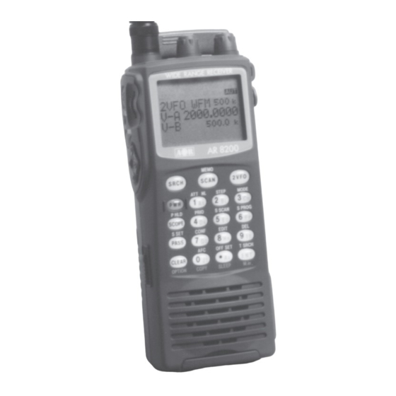
- Page 1 The Superior ® AR820 0 WIDE RANGE ALL MODE RECEIVER 530 kHz ~ 2040 MHz OPERATING MANUAL...
-
Page 2: Table Of Contents
Section 1 (1) AR8200 Index (1) Index ..........................1-1 Introduction ........................1-2 Take care of your radio ....................1-3 Attention while operating ..................... 1-4 Accessories supplied ....................1-5 Controls & functions ..................... 1-5-1 Keypad ........................1-5-2 Summary of keys ...................... 1-5-3 Side panel ......................... - Page 3 4-3-2 Starting VFO search ....................4-3-3 Forcing VFO search to resume & changing search direction ........4-3-4 Locking out unwanted frequencies (PASS) .............. 4-3-5 Saving active frequencies to memory ..............4-3-6 Exiting VFO search ....................4-4 VFO environment menu ....................4-4-1 VFO SCAN .......................
- Page 4 7-9-4 Editing the contents of the select scan list ............... 7-9-5 Deleting all select scan channels ................(8) Search mode ....................... 8-1 Search types ........................ 8-1-1 Program search overview ..................8-2 Starting program search ....................8-2-1 Reversing the direction of search ................8-2-2 Forcing the search to resume ...................
- Page 5 (14) Configuration menu ....................14-1 CONFIG BEEP ......................14-2 CONFIG LAMP ......................14-3 CONFIG CONTRAST ....................14-4 CONFIG Power save ....................14-5 CONFIG Auto power off ..................... 14-6 CONFIG REMOTE BPS ..................... 14-7 CONFIG FREQ DISP ....................14-8 CONFIG GLOBAL write protect ................. 14-9 CONFIG Opening message ..................
-
Page 6: Introduction
© This manual is protected by copyright AOR Ltd 1998. No information contained in this manual may be copied or transferred by any means without the prior written consent of AOR Ltd. AOR and the logo are trade marks of AOR Ltd. -
Page 7: Attention While Operating
Section 1-2, 1-3 Operating anomalies Should the AR8200 appear to behave strangely, normal operation may be easily achieved by resetting the microprocessor. Two scenarios may be encountered due to power transients etc: Symptom: LCD remains on, no control of the keypad. Action: Remove any connection to external power such as the charger or cigar lead, remove one NiCad battery and count to thirty! Re-fit the battery and press the power switch again. -
Page 8: Accessories Supplied
Section 1-3, 1-4 more efficient means of monitoring the most wanted frequencies as you have targeted 100% what you most want to hear, by contrast searching is very inefficient for day-to-day monitoring. Note: It is very important that the squelch is advanced to cancel background noise for the search &... -
Page 9: Controls & Functions
Section 1-5 1-5 Controls & functions Controls are located on the top, front and left hand side of the AR8200, a brief identification is given here: 1. Rotary volume control 2. Rotary squelch control 3. BNC aerial socket 4. Function key 5. -
Page 10: Keypad
Section 1-5-1 1-5-1 Keypad Keypad conventions Most keys have multiple functions, their functions are printed on the cabinet. However due the restriction of available size, not all facilities can be shown on the keypad printing. To ease access to the many facilities, two formats are employed:- Push and release the key quickly to access the required facility. -
Page 11: Summary Of Keys
Section 1-5-2 1-5-2 Summary of keys The main keypad is located on the front cabinet of the AR8200 with other keys located on the left hand side. When powered from internal batteries with the lamp configured to AUTO, the lamp will automatically illuminate when keys are pressed and will stay illuminated for five seconds after the last key press. - Page 12 Section 1-5-2 PUSH this key to place the AR8200 into 2VFO mode where you may receive spot frequencies and ‘generally monitor activity’. The LCD displays two lines of frequency readout, the upper (larger) being the current receive frequency. The LCD legend “2VFO” confirms selection with each VFO being identified as “V-A”...
- Page 13 Section 1-5-2 in 2VFO mode to access the VFO PASS menu which extends to include the SEARCH bank pass edit menu. in 2VFO, SEARCH or SCAN mode to access the SELECT SCAN edit menu. PUSH to abort entry via the keypad. to select the optional SLOT CARD when fitted.
- Page 14 Section 1-5-2 Numeric figure four during frequency input. Selection of memory/scan bank “D” or “d” and search bank “D” or “d” or “N” or “n”. toggles the priority facility on/off (assuming that one has already been assigned using the priority menu). The LCD legend “PRI” confirms when priority has been selected. to access the priority menu where the data from a memory channel may be assigned for priority use.
- Page 15 Section 1-5-2 Numeric figure nine during frequency input. Selection of memory/scan bank “I” or “i” and search bank “I” or “i” or “S” or “s”. will delete the currently displayed memory channel during memory read or scan. accesses the delete menu where search banks, VFO pass frequencies, memory banks, select channel tags, channel protect status &...
-
Page 16: Side Panel
Section 1-5-3 1-5-3 Side panel The left hand side of the AR8200 comprises of three push keys, a nest of four arrow keys and a rotary main dial. An eject slider is also provided to release the optional SLOT CARD. FUNCTION KEY The function (shift) key is used to select the second function of keypad facilities. -
Page 17: Power Supply And Battery Charging
Section 1-5-3, 1-6, 1-6-1 ARROW KEYS The arrow keys are laid out as a group of four keys (up, down, left and right). This format is particularly convenient when used with the thumb of the left hand (although you may use it with the middle finger of your right hand etc) for navigation through on-screen menus. - Page 18 Section 1-6-1 Dry cells such as Alkaline or Zinc / Manganese may be used but cannot be charged inside the AR8200, if dry cells are fitted to the AR8200, remove dry cells before using the cigar lead or connecting the charger or external power. The AR8200 charging circuit is not designed to recharge dry cells or NiMHi batteries, if these are to be recharged, they must be removed from the AR8200 and charged in a specialist external charger following the manufacturers recommendations.
-
Page 19: Charging The Nicads
Section 1-6-2, 1-6-3 1-6-2 Charging the NiCads It is possible to charge the supplied NiCad batteries while still fitted inside the AR8200 using the charging unit provided. Switch off the AR8200 then connect the plug from the charging unit to the 12V d.c. input socket on the right hand side of the AR8200 cabinet. -
Page 20: Battery Considerations
Section 1-6-3, 1-6-4 It is advisable to switch the AR8200 off when starting the vehicle as the starter motor often causes power surges. Some vehicles require their ignition to be ON for the cigar socket to operate. 1-6-4 Battery considerations The supplied NiCads are not factory charged. -
Page 21: Making The Ar8200 Ready For Operation
Section 2, 2-1 (2) Making the AR8200 ready for operation 2-1 LCD (Liquid Crystal Display) All relevant operational information is provided via the large LCD. To see all the available LCD legends, and to test the LCD, an LCD test routine has been provided. and hold the key then switch the AR8200 on,... -
Page 22: Connect The Aerial (Antenna)
Section 2-1, 2-2, 2-3 2-2 Connect the aerial (antenna) Two aerials are supplied with the AR8200: BNC mounted whip aerial MW bar aerial For general reception on the VHF/UHF bands, connect the supplied whip aerial to the BNC socket on the top panel of AR8200. This is a bayonet connector, line up the slots, press down firmly and twist clockwise, the guides will position, then let go. -
Page 23: Keypad And Knobs
Section 2-4, 2-4-1, 2-4-2, 2-4-3 2-4 Keypad and knobs... what you need to know ‘most’ Several of the keys have special characteristics, a summary was given in section 1-5-1 of this manual where it was explained that several keys have two of three functions associated with them. IMPORTANT Note: Make sure you understand the PASS (LOCKOUT / SKIP) operation before using the PASS facility, this applies to the PROTECT facility too, make sure both facilities are understood before you attempt to use them. -
Page 24: Clear Key
Section 2-4-4, 2-4-5, 2-4-6 2-4-4 CLEAR key to abort entry via the keypad... if in doubt, to return to the previous display menu or operating mode. to select an option when an optional SLOT CARD is used. and hold the key while powering on the AR8200 to soft reset the microprocessor should the AR8200 appear to behave strangely... -
Page 25: Basic Manual Operation Of The Receiver
Section 3, 3-1, 3-2 (3) Basic manual operation of the receiver The following information explains how to tune to a specific frequency, change receive mode etc. Note: When the AR8200 is switched OFF, all VFO data will be automatically stored into flash-ROM memory storage. - Page 26 Section 3-2 Both VFO frequencies are displayed in parallel format on the LCD, one above the other. The ‘active’ VFO (the one which is currently receiving) is displayed using a large font centrally on the LCD, the ‘standby’ VFO is shown on a lower line using a smaller font size. key to first select ‘VFO mode’...
-
Page 27: Entering A Frequency Using The Numeric Keypad
Section 3-2, 3-3 Transfer to active VFO When the AR8200 has stopped on an active frequency in memory read, scan or search mode, use the key sequence to transfer the frequency to the active (upper VFO). The AR8200 will revert to 2VFO mode where the frequency may be monitored. 3-3 Entering a frequency using the numeric keypad While in VFO mode, enter the required frequency using MHz format followed by Example of frequency entry 80.8 MHz... -
Page 28: Correcting Frequency Input
Section 3-3, 3-4, 3-5 displayed to the right of the kHz position. This is to ensure easy recognition of short wave frequencies which are often listed as ‘kHz’ in frequency guides. If an attempt is made to enter an ‘out of range’ or invalid frequency (such as 2345 MHz or 0.09 MHz) the error beep will sound (if beep is enabled) and the LCD returns to the previous frequency prior to frequency input. -
Page 29: And Keys
Section 3-5, 3-6 Note: In AM and FM modes with the squelch open, reception will be momentarily interrupted while tuning and the “S” squelch legend will flash as tuning progresses, a ‘chuff-chuff’ sound will accompany tuning, this is normal. Fast tuning keys may be used to tune the receiver at a rate TEN TIMES FASTER than the selected step size. -
Page 30: Changing Receive Mode
Section 3-7, 3-7-1, 3-7-2 3-7 Changing receive mode Due to the necessities of signal bandwidth, channel occupancy and transmission efficiency, different receive modes are used by various services. In addition to this the specification for tuning step and receive mode are allocated by departments of Governments following International discussions so are not consistent throughout the world. - Page 31 Section 3-7-2 Generally speaking the following modes will apply: AUTO Receive mode and tuning step will be selected automatically using the pre-programmed auto bandplan data. Wide band Frequency Modulation - used by VHF and UHF broadcast stations as excellent audio quality is available due to the relatively wide frequency bandwidth employed.
-
Page 32: Changing Tuning Step Size
The AR8200 being a hand held wide band receiver cannot offer the receive performance of a dedicated short wave receiver such as the AOR AR7030 or base wide band receiver AOR AR5000. This is due to the limitation of size, as a result the receiver’s AGC (Automatic Gain Control) circuitry band pass circuits and reference stability cannot be as complex. - Page 33 Section 3-8 Should you wish to change the default tuning step size The third main text line of the LCD will display the current default size (perhaps “25.00” kHz). If the reverse LCD legend “AUT” displayed in the upper right corner of the LCD, this indicates that AUTO MODE / STEP is currently selected.
-
Page 34: Step-Adjust
Section 3-8, 3-9, 3-9-1 The display doesn’t correct immediately upon frequency entry to allow you to enter the ‘STEP-ADJUST’ menu to change the step size and step-adjust in order to help track unusual band plans. Note: AUTO-STEP, STEP-ADJUST and AUTO-MODE are linked to the pre-programmed bandplan data. -
Page 35: Cancelling Step Adjust
Section 3-9-1, 3-9-2, 3-93 Access the STEP menu using the key sequence . Use the main dial to select a step size of 20 kHz (do NOT press enter!). to access the STEP-ADJUST menu. Accessing this menu will activate the step-adjust facility, the “ADJ”... - Page 36 Section 3-93 However, the STEP-ADJUST facility is used to address this situation. With the above in mind, 58.445 MHz with 15 kHz steps in mind, while in VFO mode, key in the start frequency of 58.445 MHz Access the STEP menu using the key sequence .
-
Page 37: Frequency Offset
Section 3-9-3, 3-10, 3-10-1 With this example of 145.210 MHz with 14 kHz steps in mind, while in VFO mode, key in the start frequency of 145.210 MHz Access the STEP menu using the key sequence . 14 kHz is not a standard size provided by rotating the main dial so key in the required 15 kHz step size. -
Page 38: Entering New Frequency Offset Data
Section 3-10-1, 3-10-2 The third line will display “OFFSET 00” with “00” indicating that frequency offset is currently off, there will be no “DUP” legend displayed when the frequency offset is OFF. The bottom line of LCD will display “- - - . - - - -“ indicating that no offset is stored. -
Page 39: Attenuator
Section 3-10-2, 3-11, 3-12 For example, use the main dial until the LCD displays “OFFSET 01”, the bottom line of LCD will display “- - - . - - - -“ indicating that no offset has been previously stored. If data is stored, the offset value will be displayed on the bottom line of the LCD and may be overridden. -
Page 40: Afc - Automatic Frequency Control
Section 3-12, 3-13 The noise limiter has two settings, on and off. When the noise limiter is ON, the legend “NL” appears on LCD. To toggle the noise limiter on/off the legend “NL” confirms selection and the noise limiter will be active in AM and SSB modes. - Page 41 Section 3-13 The distance in kHz which the AR8200 can ‘pull’ depends upon receive mode, IF bandwidth and signal strength… the wider the filter and stronger the signal then the further AFC can pull. Typically AFC will pull in the region of ± 5 kHz to ± 15 kHz, the maximum value for AFC is set to ±...
-
Page 42: Vfo Enhanced Facilities
Section 4, 4-1, 4-1-1 (4) VFO enhanced facilities As well as providing a tuning data storage, the two VFOs offer additional features including quick memory, VFO scan, VFO search and VFO environment. 4-1 Quick memories While monitoring in 2VFO mode, 10 ‘quick memories’ are provided for easy saving of current VFO data and simple recall at a later time. -
Page 43: Recalling Quick Memories
Section 4-1-2, 4-2 4-1-2 Recalling quick memories Once a few quick memory channels have been stored, key a different frequency into the VFO to assist identification of recalled data (until you fully understand the process). While in 2VFO mode The LCD will display one of the quick memory channels which have been stored, use the keys to scroll through the list which contains up to ten frequencies. -
Page 44: Vfo Scan Sampling Time
Section 4-2, 4-2-1, 4-3, 4-3-1, 4-3-2 on the next line. The third line displays “ON” and “OFF” with the “OFF” legend displayed in reverse contrast to show that it is currently selected (default). To toggle the VFO SCAN on/off key or use the main dial or keys. -
Page 45: Forcing Vfo Search To Resume & Changing Search Direction
Section 4-3-2, 4-3-3, 4-3-4 Note: While in VFO mode, if the keypad or key is used, the current status of the audio with respect to the squelch control will be maintained. If the squelch is closed before you PUSH a key, the audio will remain muted until the key sequence is completed even if the frequency becomes active (and vice-versa…... -
Page 46: Saving Active Frequencies To Memory
Section 4-3-4, 4-3-5 If PASS channels have already been tagged for VFO SEARCH the legend “PASS xx” will be displayed where “xx” indicates that data is present. If no pass frequencies have been tagged, the legend “PASS 00 ----.----” will be displayed. The frequency pass contents may be reviewed using the keys or main dial. -
Page 47: Exiting Vfo Search
Section 4-3-6, 4-4, 4-4-1, 4-4-2 4-3-6 Exiting VFO search To exit VFO search, to return to the VFO mode (the frequencies in use before VFO search was initiated will be displayed). Alternatively use the keys to exit VFO search. 4-4 VFO environment menu The VFO has a special menu to enable VFO scan to be toggled, VFO search to be customised, VFO auto store to be toggled on/off, memory bank “J”... -
Page 48: Vfo Search Level Squelch Environment
Section 4-4-2, 4-4-3 VFO search DELAY is configured via the VFO environment menu, use the key sequence to access the VFO environment menu. key once to move to the DELAY parameter. to toggle the status between 2.0s / HOLD / OFF, the default is 2.0s. -
Page 49: Vfo Search Voice Squelch Environment
Section 4-4-3, 4-4-4, 4-4-5 to accept the changes and return to the display prior to accessing the VFO environment menu. Alternatively you may move to the next option (VFO VOICE squelch) by pressing the key. While in VFO or VFO search, the LCD legend “LSQ” is displayed to indicate that VFO level squelch is in operation. -
Page 50: Vfo Auto Store Environment
Section 4-4-5, 4-4-6, 4-4-7 VFO FREE search is configured via the VFO environment menu, use the key sequence to access the VFO environment menu. key four times to move to the FREE parameter. to toggle between OFF and 5 seconds (the default is off). Use the main dial to increment value by 1s or use the keys to increment by 5s. -
Page 51: Vfo Quick Memory Environment
Section 4-4-7, 4-4-8 If bank “J” contains data, the legend “J00” will be displayed (the number indicating the presence of data), if no data is held in bank “J” the legend “J--“ will be displayed. to delete the contents of bank “J”, this will take a few seconds to action by the CPU. The legend “J--“ will be displayed to confirm deletion. -
Page 52: Memory Channels & Banks
Section 5, 5-1 (5) Memory channels & banks It is convenient to store commonly used frequencies into a memory channel along with mode etc, this saves having to key the data in over and over again. Memory read is very straightforward and quick when compared to re-typing all data. -
Page 53: Storing Vfo Frequencies & Data Into Memory
Section 5-1, 5-2 Auto-store When shipped from the factory, memory bank “J” is reserved for auto-store of memory channels from search mode. This is a useful facility to quickly build a list of active frequencies. Please refer to section 8-7-5 of this manual for further information regarding AUTO-STORE. Dynamic memory bank resizing The lettered memory banks are regarded as a ‘pair’... - Page 54 Section 5-2 to place the AR8200 into VFO mode. to select the desired frequency, the mode and step size will be automatically set by the AR8200 microprocessor. key for more than one second to enter ‘memory input’ mode. One line up from the bottom of the LCD will be the legend “M-WRITE”...
-
Page 55: Another Example Of Memory Write
Section 5-2, 5-2-1 If the memory location has been used previously and a text comment is displayed, delete the existing comment. Note: It is possible to use keypad short cuts to select text characters, please refer to section 13-2 of this manual for further details. You may accept the new frequency and text comment “AIRBAND”... -
Page 56: Automatic Memory Allocation
Section 5-2-1, 5-2-2, 5-3 To recap: Once the three digit memory location has been selected, the 2 second keypad time-out does not apply to the rest of the sequence. d) To add the text comment “70cm”, then use the main dial to select the text and the keys to move position of text input. -
Page 57: Memory Read "M.rd
Section 5-3, 5-4 The memory bank write protect may be toggled on/off using the SCAN environment menu accessed by the key sequence followed by four pushes of the key. to toggle bank select on/off and to accept the changes and exit the menu. Please refer to section 7-8-6 of this manual for details on MEMORY BANK write PROTECT. -
Page 58: Memory Channel Review / Hunt
Section 5-4-1, 5-5 5-4-1 Memory channel review / hunt From VFO mode to enter memory read “M.RD” mode. The main dial may be rotated or the keys pushed to review, hunt for and select memory channels one by one, channels with no data stored will be skipped. keys to move between memory banks one by one. -
Page 59: Memory Channel Editing
Section 5-5-1, 5-5-2, 5-6, 5-7 5-5-1 Memory channel editing It is possible to copy, move, swap and edit memory channels to assist the management of data. Please refer to section 9 of this manual regarding the EDIT menu. 5-5-2 Adding text names to memory banks To assist with memory management and identification, memory banks can be named. -
Page 60: Priority Operation
Section 5-7, 6 The LCD will initially display the legend “M-BANK” , the currently selected memory bank ‘pair’ (i.e. D/d or A/a or C/c etc) and the current size allocation for the bank displayed i.e. A:50 a:50 for memory bank “A/a” with the allocation of 50 channels for “A” and 50 channels for “a”, this split of 50/50 being the default. -
Page 61: Engaging Priority Channel
Section 6, 6-1, 6-2 Note: The priority mode is automatically suspended during entry of frequencies via the keypad, this prevents the receiver from changing frequency while you are busy programming. Priority operation is disabled when the band scope is in operation. 6-1 Engaging PRIORITY channel Once engaged, the default channel used for PRIORITY is “A00”... -
Page 62: Changing The Priority Channel Data Pickup Channel
Section 6-2, 6-2-1, 6-2-2 This is accomplished by using the “PRIO SET” menu accessed by the key sequence The legend “PRIO SET” appears on the top line of the LCD to confirm selection. 6-2-1 Changing the priority channel data pickup channel Should you wish the priority channel to use data contained in another memory location, access the “PRIO SET”... -
Page 63: Scan - Scanning Memory Channels & Banks
Section 7, 7-1, 7-2 (7) SCAN - scanning memory channels & banks The AR8200 has a SCAN mode whereby the contents stored in the MEMORY CHANNELS ARE AUTOMATICALLY RECALLED AND MONITORED very quickly for activity - scanned. * It is important that you do not confuse SCAN and SEARCH modes. * SEARCH mode (covered later in this manual) automatically TUNES THE RECEIVER THROUGH ALL FREQUENCIES between two specified frequency limits looking for active frequencies. -
Page 64: Starting To Scan
Section 7-2, 7-3 When in SCAN MODE, the memory banks are referred to as “SCAN BANK A”, “SCAN BANK B”, “SCAN BANK f” etc rather than using the full title “SCAN MEMORY BANK A”, “SCAN MEMORY BANK B” etc. This terminology has been employed to make the explanation of and referral to SCAN MEMORY BANKS (SCAN BANKS) less long-winded. -
Page 65: Transfer Of Active Memory To Vfo
Section 7-3, 7-3-1, 7-4, 7-5 When SCAN has been selected, only the currently displayed memory bank WHICH CONTAINS DATA will be SCANNED (as bank link is default off), receive mode and frequency are unimportant. Any memory channels which contain no data (empty) will be ignored (skipped). 7-3-1 Transfer of active memory to VFO When the scan process is paused on a busy channel, to transfer the current memory... -
Page 66: Toggling Memory Channel Pass
Section 7-5, 7-5-1, 7-5-2 unwanted channels so that they are skipped when scanning. PASS does not delete the memory contents but simply ‘tags’ the channel to be skipped. In memory read, the PASS tag may toggled on/off and the tags removed in one operation using the delete pass channel facility of the DELETE menu. -
Page 67: Deleting Memory Channels
Section 7-6, 7-6-1, 7-6-2, 7-7 7-6 Deleting memory channels Although it is possible to over-write memory channels with new data, edit memory channels, swap, copy, move and to PASS (skip) them, there will be occasions when you want to delete memory channels completely. -
Page 68: Additional Scan Facilities
Section 7-7, 7-8 “BANK LINK” will be displayed on the bottom line of the LCD indicating that programming is possible. to move to the memory bank letters, then reverse highlight the letters you wish to link together as a group of memory channels to scan using the keys, to mark desired memory banks, both upper and lower case letters may... -
Page 69: Scan Delay
Section 7-8, 7-8-1, 7-8-2 Use the key sequence to access the “SCAN-GROUP” menu. Use the keys to select the SCAN-GROUP number between 1 and 9. three times to move down beyond the bank link facility and onto the additional scan environment facilities: delay, level, voice, free, mode scan. -
Page 70: Scan Voice
Section 7-8-2, 7-8-3 Use the keys to select the SCAN-GROUP number between 1 and 9. four times to display the scan environment parameter of LEVEL. as a short cut to off (which is the default). Use the main dial to increment value by 1 or use the keys to increment by 10. -
Page 71: Scan Free
Section 7-8-3, 7-8-4, 7-8-5 Note: When voice squelch is in operation, the rotary squelch control is usually best rotated to the fully anti-clockwise position. to accept the changes and return to the display prior to accessing the scan environment menu. Alternatively you may move to the next option (scan FREE time) by pressing key. -
Page 72: Write Protect Of Memory Channels & Banks
Section 7-8-5, 7-8-6, 7-9, 7-9-1, 7-9-2 as a short cut to ALL (which is the default) which will cause all receive modes to be scanned in the specified scan group. Use the main dial or keys to select the receive mode: ALL, WFM, NFM, SFM, WAM, AM, NAM, USB, LSB, CW. -
Page 73: Select Scan Environment
Section 7-9-3, 7-9-4 7-9-3 Select scan environment The select scan environment may be customised in respect of DELAY, LEVEL, VOICE, FREE and MODE. The current SCAN-GROUP selection is used by select scan. To access the scan group environment menu . For further information regarding the scan group environment please refer to section 7-8 of this manual. -
Page 74: Deleting All Select Scan Channels
Section 7-9-4, 7-9-5 If you wish to add more select scan channels once to move upward to the new end of the list and repeat the process. to exit the select scan menu. It is possible to delete the entire select scan list in one go using the DELETE menu, this is very useful to enable rapid changes to the select scan list content. -
Page 75: Search Mode
Section 8, 8-1, 8-1-1 (8) Search mode In search mode, the AR8200 is programmed to automatically tune between two specified frequency limits looking for activity. Please refer to section 1-3 of this manual if you do not fully understand the terminology of SEARCH. -
Page 76: Starting Program Search
Section 8-1-1, 8-2, 8-2-1, 8-2-2, 8-2-3 To assist testing in the factory, several search banks may be programmed with data (which can be easy deleted or over-written). This pre-programming is useful to ease familiarisation during the early days of operation… so that when you push a key there is something already programmed to work! 8-2 Starting program search Presuming that data is already stored into a search bank…... -
Page 77: Copying An Active Frequency To The Vfo Or Memory Location
Section 8-2-4, 8-3 8-2-4 Copying an active frequency to the VFO or memory location It is convenient to transfer an active frequency from search to VFO or memory for periods of extended listening. Copy to VFO When the search process is stopped on an active frequency, key to transfer the current receive frequency to the single VFO where it may be monitored. - Page 78 Section 8-3 Recalling banks K - T requires use of the ‘SHIFT’ Recalling banks k - t requires use of the ‘case’ command before the letter key, this ‘shift’ and ‘shift’ command before the letter key: command is the use of the key before a second numeric key is pushed.
-
Page 79: Programming A Search Bank
Section 8-4 8-4 Programming a search bank Each of the 40 search banks may be programmed with different frequency limits, receive modes, step size etc as listed in section 8-1-1 of this manual. to access the “SRCH-PROG” menu. Use the main dial or keys or keypad to select the bank you wish to program or over write. - Page 80 Section 8-4 Note: If a step-adjust value is already programmed into the search bank, the step-adjust menu will be automatically displayed when accessing the step input menu. STEP ADJ+ If you with to manually enter a step-adjust value for tracking unusual band plans , the “STEP ADJ+”...
-
Page 81: Locking Out Unwanted Active Frequencies (Pass)
Section 8-5, 8-5-1 8-5 Locking out unwanted active frequencies (PASS) It is possible to lock out (PASS) unwanted frequencies while in program search mode, this is useful to eliminate unwanted permanent transmissions. It is important to understand the PASS facility before using the key or transmissions may be missed. -
Page 82: Search Bank Link
Section 8-5-1, 8-6 To delete the entire contents of the current search pass list , the legend “PASS 00 ----.----” confirms deletion. The search pass list may also be deleted using the DELETE menu, refer to section 10-1 of this manual. Adding new pass frequencies Access the search pass list, If you are currently searching , the “SRCH PASS”... -
Page 83: Additional Search Facilities
Section 8-6, 8-7 Next reverse highlight the letters you wish to link together as a group using the keys, to mark the desired search banks, both upper and lower case letters may be highlighted in the same group. The selected banks (which will form a large group) will be displayed in REVERSE contrast on the LCD. -
Page 84: Search Delay
Section 8-7, 8-7-1 DELAY OFF / HOLD / 0.1 - 9.9 seconds (default 2.0s) LEVEL OFF / 1 - 255 (default OFF) VOICE OFF / 1 - 255 (default OFF) FREE OFF / 1 - 60 seconds (default OFF) AUTO STORE ON / OFF (default OFF) DELETE J Yes / No (using... -
Page 85: Search Level
Section 8-7-2, 8-7-3 8-7-2 Search LEVEL The search LEVEL squelch parameter causes the AR8200 to check the signal strength and to only open the squelch when the signal strength is above the stated level (which is programmable in 256 steps). The limits are OFF and 1 to 255 (default off). -
Page 86: Search Free
Section 8-7-3, 8-7-4 as a short cut to off (which is the default). Use the main dial to increment value by 1 or use the keys to increment by 10. While adjusting voice squelch, the “ ” legend will be displayed to the left of the value “VOICE 12”... -
Page 87: Auto Store
Section 8-7-5, 8-7-6 8-7-5 AUTO STORE Auto store causes the first 50 active frequencies located during search to be automatically written to memory bank “J” (channels J00 to J49). If bank “J” is full, auto store will not function. Note: Memory banks are dynamically configurable so that bank “J” has 50 channels at default buy may be configured to provide 10, 20, 30, 40, 50, 60, 70, 80, or 90 channels. -
Page 88: Deleting Search Banks
Section 8-7-7, 8-7-8 8-7-7 Deleting search banks A delete menu is provided so that you can delete program search data (of course you may simply over-write the data too) and frequency pass channels. You cannot delete search banks which have been write protected. -
Page 89: Edit Menu
Section 9, 9-1 (9) EDIT menu The EDIT menu is a powerful feature which simplifies the management of data and provides the following operations: COPY MEM-CH loads one memory channel to save to another location COPY MEM-BNK loads one whole memory bank to save to another location COPY SEARCH loads one search bank to save to another location MOVE MEM-CH... -
Page 90: Edit Copy Memory Bank
Section 9-1, 9-2 Note: If the SAVE location is write protected, the legend “PROTECT” will be displayed. You must remove write protect from the SAVE memory location before you can copy new data to that location. You may remove the write protection for one or all memory channels, refer to sections 11-1 &... -
Page 91: Edit Copy Search Bank
Section 9-2, 9-3, 9-4 Note: If the SAVE bank location is write protected, the legend “PROTECT” will be displayed. You must remove write protect from the SAVE memory bank before you can copy new data to that location, individual memory channel write protect is ignored. Refer to the write protect section 11 of this manual. -
Page 92: Edit Swap Memory Channel
Section 9-4, 9-5 Two data input lines are presented LOAD and SAVE. The cursor will be positioned on the LOAD line. “LOAD” represents the memory channel which you would like to move (this is the data you want). Use the main dial to select channel number and the keys to select bank, alternatively type in a three digit memory location via the keypad. -
Page 93: Edit Memory Channel
Section 9-5, 9-6 to swap the memory channel data between CH-A and CH-B. Both CH-A and CH-B display the memory channel location of CH-A. The process may be repeated for other locations. Note: If either location is write protected, the legend “PROTECT” will be displayed. You must remove write protect from the memory location before you can swap new data to that location. -
Page 94: Edit Search Protect
Section 9-6, 9-7 to move to the “MODE SET” line. Use the main dial or keys to select receive mode. key may be used as a short cut to “AUTO”. In auto, receive mode & tuning step will be read from the pre-programmed auto band plan data. to move to the “SET STEP”... -
Page 95: Delete Menu Facilities
Section 10, 10-1 (10) DELETE menu facilities It is often desirable to delete many data entries in one go such as memory channels and pass frequen- cies. To assist with data management a DELETE menu is provided which offers the following facilities:- DEL SRCH delete a search bank DEL SRCH PASS... -
Page 96: Delete Vfo Pass
Section 10-1, 10-2, 10-3 If frequency pass channels exist for the current bank, the legend “DEL PASS xx” will be displayed with the “xx” number (00 to 49) indicating that data is present. If no data is present the legend “DEL PASS --”... -
Page 97: Delete Select Scan Channels
Section 10-3, 10-4, 10-5 If no memory data exists in the selected memory bank, the legend “MEM-BANK X--” will be displayed. If memory data does exist, the legend “MEM-BANK Xxx” will be displayed with the “xx” number (00 to 89) indicating that data is present. To delete MEM-BANK data , the legend “MEM-BANK Xxx“... -
Page 98: Delete Memory Channel Pass
Section 10-5, 10-6 to exit the menu returning to the standard display, alternatively to move to the next item in the menu “DEL MEM PASS”. 10-6 DELETE memory channel pass It is possible to remove the channel pass ‘tags’ from all memory channels in one go using the DELETE menu. -
Page 99: Write Protect
Section 11, 11-1, 11-2, 11-3 (11) Write protect It is possible to write protect memory channels, whole memory banks, search banks and ‘globally protect’ memory to prevent data being accidentally over-written. 11-1 Memory CHANNEL write protect It is possible to protect memories while writing new data, toggle the protect status of previously stored memory channels and to delete all memory channel protect tags in one go. -
Page 100: Channel Protect Delete
Section 11-3, 11-4,11-5 Again use the key to toggle write protect status on/off… in this manner you may quickly change the protect status of several memory channels. to save the changes and exit the menu. Note: Channel write protect is ignored when copying complete memory banks or when copying ALL data. -
Page 101: Search Bank Write Protect
Section 11-6, 11-7 11-6 Search bank write protect It is possible to write protect individual search banks to prevent accidental deletion. The search bank write protect may be toggled on/off using the EDIT menu. to access the edit menu. key twelve times to display the “SRCH PROT” menu. -
Page 102: Text Search And Input
Section 12, 12-1 (12) TEXT search and input It is possible to add text comments (using a maximum of 12 characters) to:- 1. individual memory channels 2. memory banks 3. search banks This aids later identification of stored data. It is also possible to TEXT SEARCH the AR8200 to automatically hunt for matching text, a minimum of 2 characters are required for TEXT SEARCH, in practical terms a minimum of 3 characters are recommended and the more characters used, the faster the resultant search. -
Page 103: Text Search
Section 12-2 12-2 Text search For fastest text search and greatest reliability, place the AR8200 into memory read, scan or search mode (it takes a long time while in VFO mode and may fail under certain circumstances). Text search may take up to 30 seconds to complete. -
Page 104: Short Cut Keys
Section 13, 13-1 (13) SHORT CUT keys There are various short cut key combinations available for use with the ‘FLASHING FUNCTION’. When the “FUNC” legend is flashing, two keys are held simultaneously to provide a short cut to specific functions which would otherwise require greater key presses or use of a menu. 13-1 Short cut menu access SCAN short cuts for flashing “FUNC”... -
Page 105: Short Cut Text Entry
Section 13-2 13-2 Short cut text entry Entering text into memory channels, memory banks and search banks can be quite long winded. To speed up the process, while the “FUNC” legend is flashing two keys may be pushed in sequence to provide a short cut a variety of alphabet letters (upper case), numbers and symbols. -
Page 106: Short Cut Text Entry, Keypad With
Section 13-3 13-3 Short cut text entry, keypad with keys Text may also be entered using a combination of the keypad and keys. While in a text input menu, for flashing “FUNC” legend then refer to the following table. Look for the required character in the table then PUSH the key shown to the horizontal-left followed by key shown above the required character (do not push both keys together). -
Page 107: Configuration Menu
Section 14, 14-1, 14-2 (14) Configuration menu The configuration (CONFIG) menu is used to set fundamental operating parameters and other variables which do not appear in any other menu heading. BEEP Confirmation & error tone LAMP LCD & keypad illumination CONTRAST LCD contrast adjustment POWER-SAVE... -
Page 108: Config Contrast
Section 14-2, 14-3 The lamp may be configured in three ways: AUTO This setting is relevant when operating from internal batteries only. The lamp will automatically illuminate when the front panel and side panel keys are used. The lamp will remain illuminated for a further five second after the last key push and will then switch off. -
Page 109: Config Power Save
Section 14-4 14-4 CONFIG Power save The POWER SAVE facility may be used to help the receiver to operate for longer periods of time between battery recharging. Power save is default OFF to prevent confusion while the AR8200 is in a “dormant”... -
Page 110: Config Auto Power Off
Section 14-4, 14-5, 14-6 Use the main dial or keys to vary the cycle value, the key may be used as a short cut to 3.0 seconds. to accept the data and return to a standard display. Alternatively to abort entry or to move to the next item on the config menu (AUTO PWR-OFF). -
Page 111: Config Freq Disp
Section 14-6, 14-7, 14-8 to move the cursor to the “RMT-ID” selection point. Use the main dial or keys change the AR8200 RS232 IDENTIFICATION ADDRESS when multiple units are connected to the same port. It is possible to connect up to 99 units at once, each radio being assigned a different address. The value is adjustable between 00 and 99, the default is 00. -
Page 112: Config Opening Message
Section 14-8, 14-9 Use the main dial or keys or key to toggle between ON and OFF (the default is off). to accept the data and return to a standard display. Alternatively to abort entry or to move to the next item on the config menu (OPENING MESSAGE). 14-9 CONFIG Opening message It is possible to display a welcome message while the AR8200 is powering up and collating its ‘boot-up’... -
Page 113: Band Scope
Section 15, 15-1 (15) Band scope The AR8200 is equipped with a flexible band scope function which is capable of graphically displaying band activity. The maximum frequency span width is 10 MHz, you may zoom in on activity to a span width of 100 kHz. -
Page 114: Exit From Band Scope
Section 15-2, 15-3, 15-4, 15-5 15-2 Exit from band scope To exit the band scope 15-3 Setting frequency span width (waveform enlargement) The frequency span width may be adjusted between the limits of 10 MHz (default) to 100 kHz using keys. -
Page 115: Entering A New Centre Frequency
Section 15-6, 15-7, 15-8, 15-9 15-6 Entering a new centre frequency To enter a new centre frequency, simply tap the wanted frequency into the keypad. The legend “CENTRE FREQ” will be displayed on the top line of the LCD with entry taking place on the second line. To complete entry in MHz format . -
Page 116: Loading Stored Band Scope Traces From Memory
Section 15-10 15-10 Loading stored band scope traces from memory Providing a trace has been previously stored to memory, it is possible to recall it to display using the key sequence . The legend “RCV” (in the place of “MKR”) indicates that a stored trace is currently being displayed. -
Page 117: Sleep
Section 16 (16) Sleep It is possible to instruct the AR8200 to automatically switch-off after a predetermined time, this is particularly useful if you know that you may be called away from the receiver or listen to it while in bed and don’t want the batteries to become completely flat. -
Page 118: Option Socket
Section 17 (17) Option socket The option socket is mounted on the right hand side of the cabinet underneath the 12V d.c. input socket. The socket is protected from dust by a grey rubberised case stopper which is hinged toward the front of the cabinet. -
Page 119: Rs232 Operation
Section 17-1, 17-2 17-1 RS232 operation Connect the optional CC8200 computer control lead to the option socket and connect to a computer. The command protocol is provided with the CC8200 on floppy disk as an Adobe Acrobat PDF file. The RS232 parameters may be defined using the CONFIG menu. Baud rates (transfer speed) may be set to 4800, 9600 or 19200bps. -
Page 120: How To Clone Data
Section 17-2-1 17-2-1 How to clone data Ensure that the RS232 baud rate is set to the same speed for both radios and that the address is set to 00 on both units (refer to section 14-6 of this manual for information on the CONFIG menu settings). - Page 121 Section 17-2-1 Note: If you make a mistake during programming, it is possible to key to exit the menu. However, be careful and get it right in the first place… this is the best way of avoiding the possibility of data corruption. Write protect Individual memory channel protect and search bank protect status is ignored, however global protect will prevent data being cloned between radios.
-
Page 122: Slot Card Socket
18-1 Optional slot cards Any ‘one’ optional card may be fitted at any time. Do not use anything other than the ‘genuine’ AOR slot cards. The slot card has five main uses: 1. VI8200 Voice inverter (analogue) in 157 steps 2. -
Page 123: Removing The Slot Card
Section 18-1-1, 18-1-2, 18-2 You may wish to leave certain items selected if they are not affecting current operation in order to minimise reprogramming when slot cards are inter-changed at a later time. 18-1-2 Removing the slot card Always switch the AR8200 off when removing a slot card. To access the socket place the AR8200 on its back and open the front edge of the protective door. -
Page 124: Ct8200 Optional Ctcss Slot Card
Section 18-2, 18-3. 18-3-1 To speed up the toggling of voice inverter, effectively toggle the voice inverter option on/off. This is achieved as the default is set to voice inverter ON (by accessing the voice inverter menu) so that every time the voice inverter menu is accessed, the voice inverter is automatically activated. -
Page 125: Ctcss Search
Section 18-3-1, 18-3-2 Use the main dial or keys to make selection of CTCSS tone from the 50 available, the value cannot be adjusted when the menu is set to “OFF”. The current CTCSS tone is displayed on the last-but-one line of the LCD, the legend “... -
Page 126: Te8200 Optional Tone Eliminator Slot Card
Section 18-3-2, 18-4 The LCD legend “CT-S” will be displayed in the bottom left corner of the LCD to indicate that CTCSS SEARCH is in operation. While in 2VFO mode, the standby frequency will be replaced with the legend “CTCSS 205.5 Hz” when a CTCSS tone of 205.5 Hz has been located, otherwise the appropriate CTCSS frequency will be displayed. -
Page 127: Ru8200 Optional Record & Playback Slot Card
Section 18-4, 18-5, 18-5-1 Refer to the table to reconcile value with frequency: Frequency (kHz) Tone value Tone eliminator setting and value may be held separately in each VFO, search bank and memory channel. The squelch should be set to threshold in the usual manner. Operation continues as normal with the tone eliminator active, however if a transmission is encountered which contains a ‘pilot tone’... -
Page 128: Playback
Section 18-5-1, 18-5-2, 18-6 While recording is in progress, the second line from the bottom of the LCD (usually displaying the standby frequency in 2VFO mode) changes to a progress bar “REC =====>” indicating that recording is in progress. Once started, the recording process continues for about 20 seconds and the legend “End” is displayed when the recording process is complete. -
Page 129: Initialising (Formatting) The Em8200 Before Use
Section 18-6, 18-6-1 Note regarding write protect: If the write protect has been globally set to ON (ALL PROTECT) in the configuration menu ( ), data load will be unsuccessful and no data will be loaded. Individual memory channel protect, memory bank protect and search bank protect will be ignored during data load from the EM8200. -
Page 130: Em8200 All-Data Save And Load
Section 18-6-1, 18-6-2 The type of data will already be default to “ALL-DATA” so no action is required. to start the data save. The legend “EXT-MEM SAVING !!” will be displayed with the exclamation marks flashing to indicate that saving is in progress. The save process will take over 20 seconds to complete. -
Page 131: Em8200 All-Mem Save And Load
Section 18-6-2, 18-6-3 The load process will take over 20 seconds to complete. Once the load is complete, the AR8200 will power off/on and the LCD will revert to its previous display (VFO, scan or search etc). 18-6-3 EM8200 ALL-MEM save and load It is not necessary to save and load all of the data at times when you do not wish your search banks etc over-written. -
Page 132: Em8200 Memory Bank Save And Load
Section 18-6-4 18-6-4 EM8200 MEMORY BANK save and load The memory data ‘saved or loaded’ can be specific to one bank only. Memory banks must be saved and loaded as a pair i.e. A/a, B/b, C/c etc. Save MEM-BANK (one specific memory bank) Access the COPY EXT-MEM menu using the key sequence Select the “SAVE”... -
Page 133: Em8200 All-Srch Save And Load
Section 18-6-5, 18-6-6 18-6-5 EM8200 ALL-SRCH save and load It is not necessary to save and load all of the data at times when you do not wish your memory banks etc over-written. Instead use ALL-SRCH to overwrite all search banks in one go but to leave the memory banks etc unchanged. -
Page 134: Em8200 Internally Stored Band Scope Save And Load
Section 18-6-6, 18-6-7 key to move the cursor to the right of the legend “SRCH-BANK“ to enable selection of the desired search bank to save. Use the main dial, keys or keypad to select the desired search bank. to start the search data save. The legend “EXT-MEM SAVING !!” will be displayed with the exclamation marks flashing to indicate that saving is in progress. - Page 135 Section 18-6-7 key to move the cursor to the left of the “ALL-DATA” legend, use the keys to select “B-SCOPE”. to start the band scope data save. The legend “EXT-MEM SAVING !!” will be briefly displayed, the save process will only take a second to complete. Once the save is complete, the LCD will revert to its previous display (VFO, scan or search etc).
- Page 136 Section 18-6-7 Loading a band scope directly from external memory for viewing It is possible to load a band scope directly from EM8200 external memory for immediate display on the LCD. Use the key sequence to access the band scope load menu, the legend “B-SCOPE LOAD”...
-
Page 137: Trouble Shooting
Section 19, 19-1, 19-2 (19) Trouble shooting Should the AR8200 appear to act strangely, check out the following suggestions to see if the problem can be overcome. Failing this, switch off the AR8200, disconnect any external power connection and remove one battery from the radio (if you have batteries fitted). Wait for at least 30 seconds then re-fit the battery (if in use) or re-connect the external power and switch the radio on again with a key. -
Page 138: Trouble Shooting - Take Note Of The Following
Section 19-2, 19-3 LCD is dim. Check that the contrast is set to a sensible level (not too low) in the CONFIG menu (around 10). An LCD test facility is provided. Power-up the AR8200 while holding to switch off the test. LCD legends are all shown. -
Page 139: Optional Accessories
Section 20 (20) Optional accessories Slot cards: Five slot cards are available, only one may be fitted at a time. 1. VI8200 Voice inverter (analogue) in 157 steps. 2. CT8200 CTCSS squelch & search. 3. TE8200 Tone eliminator in 256 steps. 4. -
Page 140: Aerial (Antenna), Earths & Propagation
Discone For wide coverage in the VHF-UHF bands a compromise has to be met and the most popular aerial is a discone (AOR DA3000). Their appearance is like a large spider or umbrella without the covering material, the better models have about 16 elements. -
Page 141: Specification
Section 22 (22) Specification Frequency Range: 500 kHz to 2040 MHz (Actual frequency input 100 kHz to 2040 MHz, performance between 100 kHz to 530 kHz is not guaranteed). Receive Modes: WFM, NFM, SFM, WAM, AM, NAM, USB, LSB, CW Sensitivity: 500 kHz ~ 2.0 MHz AM: 3.50 µV (10dB S/N) - Page 142 ® AOR Ltd 2-6-4 Misuji, Taito-ku, Tokyo 111-0055, Japan. Tel: +81 3 3865 1681 Fax: +81 3 3865 1697 post@aorja.com www.aorja.com 0598...
- Page 143 NiCads, 700mAhr 12 hour charge NiCads, 1000mAhr 14 hour charge NiMH, 1500mAhr 22 hour charge SEE OVER >>> AOR LTD, 2-6-4 Misuji, Taito-Ku, Tokyo 111-0055, Japan Tel: +81 3 3865 1695 Fax: +81 3 3865 1697 e-mail: post@aorja.com web: www.aorja.com...
- Page 144 The AR8200 receiver employs standard ‘AA’ size batteries, so a range of different types can be used (NiCad, NiMH, alkaline etc). For this reason, the charging circuit cannot be optimised for any one specific type. It is most important that you do not over-charge the batteries and do not keep topping them up without first running them down.
- Page 145 AR8200 Quick reference sheet © AOR UK LTD 1998 This guide is designed to be used in conjunction with the operating manual and gives a short guide to some of the functions. There are many innovative facilities available on the AR8200, use this guide if you wish, to act as an aid to your memory until you become more familiar with the set.
- Page 146 The following keys act as short cuts when entering text {101(12-1)} When in text menus, the keys are used to move cursor position left and right. key is used to delete the current character and remaining line to the right of the cursor. The MAIN DIAL cycles through upper / lower case letters, numbers and characters.
Need help?
Do you have a question about the The Superior AR820 0 Series and is the answer not in the manual?
Questions and answers