Table of Contents
Advertisement
Quick Links
Advertisement
Table of Contents

Related Manuals for AOR AR5001D


Summary of Contents for AOR AR5001D
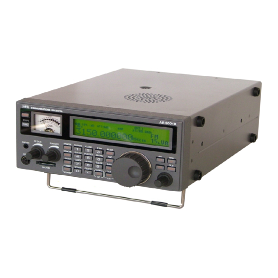
- Page 1 ® AR5001D Digital Processing Communications Receiver Operating manual AOR, LTD.
-
Page 2: Table Of Contents
2-4 KEYPAD ............................ 15 2-4-1 FRONT PANEL KEYS ......................15 GETT ING START ED ........................21 3-1 MAKING THE AR5001D READY FOR OPERATION ..............21 3-1-1 CONNECT THE ANTENNA ....................21 3-1-2 CONNECT POWER ......................21 3-2 SWITCHING ON FOR THE FIRST TIME ................... 21 3-3 VOLUME CONTROL ......................... - Page 3 5-1-3 MOVING THE SPECTRUM ....................33 5-1-4 CHANGING THE MARKER FREQUENCY ................33 5-1-5 DEACTIVATING THE SPECTRUM DISPLAY ..............33 5-2 MULTI CHANNEL RECEIVE ...................... 33 5-2-1 DUAL CHANNEL RECEIVE IN OFFSET MODE ..............33 5-2-2 DUAL BAND RECEIVE .......................35 5-2-3 TRIPLE CHANNEL RECEIVE....................36 5-3 MANAGING AN SD CARD ......................
- Page 4 8 SEARCH MODE ..........................52 8-1 SEARCH TYPE ......................... 52 8-1-1 VFO SEARCH ........................52 8-1-2 PROGRAM SEARCH ......................53 8-1-3 CYBER SEARCH .........................57 8-2 SCAN GROUP........................... 58 8-2-1 BANK LINK SETTING ......................58 8-2-2 SEARCH PAUSE .........................59 8-2-3 SEARCH DELAY ........................59 8-2-4 VOICE SEARCH ........................60 8-2-5 AUTO STORE ........................60 9 CONFIGURATION MENU ........................
- Page 5 10-12 VIDEO OUT (VIDEO OUTPUT) ..................... 76 10-13 VIDEO IMG (VIDEO MODULATION POLARITY) ..............76 11 MISCELLANEOUS FUNCT IONS ....................77 11-1 STEP ADJUST ......................... 77 11-2 SUB DIAL SETTING ........................ 78 11-3 VFO SETTING ......................... 78 11-3-1 TRANSFER FREQUENCY TO VFO .................78 11-3-2 VFO SEARCH DELAY ......................79 11-3-3 VFO VOICE SQUELCH ....................79 11-4 AUDIO FILTERS ........................
-
Page 6: Introduction
Thank you for purchasing the AR5001D Digital Processing Communications receiver. As the successor to the AR500 0A receiver, the AR5001D is designed using t he latest technology to ensure the highest level o f performance and reliability with similar key functions as the AR5000A receiver. If you are familiar with the AR5000A operations and functions, you will find it easy to use the new AR5001D receiver. -
Page 7: Main Features
Main features: Wide frequency coverage: 40 kHz to 3.15 GHz, with no interruptions (Cellular blocked for the US consumer version) 45.05 MHz IF DSP (Digital Signal Processing) HF direct sampling No AGC in the analog processing circuit Computer simulated high grade RF frontend PC controllable DDS (Direct Digital Synthesizer) local oscillator Accurate reference frequency (0.01 ppm with an optional GPS unit) -
Page 8: Take Care Of Your Receiver
The AR5001D is designed to operate from a good quality regulated DC power supply of 10.7 to 16.0 V, which should be capable of supplying 2 amps. Neve r connect the AR5001D directly to an AC power outlet. -
Page 9: Included In This Package
Operating anomalies Should the AR5001D appear to behave strangely, normal op erations may be easily achieved by performing the following steps: 1. Symptom: No control of the receiver. Action: Turn off the power switch on the front panel. Leave it off for ap proximately 10 seconds. - Page 10 High frequency (45.05 MHz) IF output The AR5001D has a 45.05 MHz analog IF output with 15 MHz bandwidth. The input signal to the 45.05 MHz IF stage is directly sent to the A/D converter for digital processing. This IF output signal may be suitab le as an RF front end for radio signal analysis applications.
-
Page 11: Front Panel
USB 2.0 stand ard interface. By using the I/Q digital output, the streamed data can be stored on a PC hard disk for future signal analysis. The I/Q digital output of the AR5001D has a wide dynamic range (without AGC processing) floating point da ta format. - Page 12 Built-in AFC (Automatic Frequency Control) AM (Amplitude Modulation) Envelope Detection (Normal AM decoder) Synchronous Detection 1. DSB (Double Side Band) synchronous 2. SSB (Single Side Band) USB/LSB (Upper Side Band/Lower Side Band) selectable synchronous AGC (Automatic Gain Control) mode/Manual RF gain mode SSB (Single Side Band) USB/LSB selectable AGC mode/Manual RF gain mode...
-
Page 16: Keypad
2-4-1 FRONT PANEL KEYS POWER This k ey is located on the upper left corner of the front panel. Press this key to power on the AR5001D. To power off the AR5 001D, press and hold this key for two seconds. FUNC The functio n key is used to select secondary functions on the keypad. -
Page 17: Squelch Co Ntrol
VFO – V. MODE / 2F. BAND Press this key to select VFO mode. The AR5001D has 5 VFOs (VFO-A through VFO-E) and the selected VFO is identified by “VA”, “VB”, “VC”, “VD”, and “VE” icons on the right bottom of the LCD. - Page 18 3 – IF BW Figure THREE for the numeric input of frequencies, bank, channel numbers, etc. Press the [FUNC] key, and press the [3] key to activate the IF bandwidth menu. In normal operation, “AUTO” will be displayed on the LCD and the IF bandwidth will be automatically selected according to the ba nd plan.
- Page 19 8 - AL ARM Figure EIGHT for the numeric input of frequencies, bank, channel numbers, etc. Press the [FUNC] key, and press the [8] key to activate the alarm function which automatically turns on the receiver at the preprogrammed time or sound a beep. 9 - SLEEP Figure NINE for the numeric input of frequencies, bank, channel numbers, etc.
-
Page 20: Receive Mode
Press this key to select the receive mode. Rotate the sub dial to select the desired received mode, and press the [MHz] key to confirm the selection. To select AUTOMODE, press and hold the [MODE] key for two seconds. The AR5001D will automatically select the receive mode, IF bandwidth, and frequency step from the pre-programmed band plan. -
Page 21: Antenna Input
ENT – This key is used to confirm entry in most menus. If this key is held for two seconds in VFO mode, the AR5001D goes in to memory write mode. Use the main dial knob to select the desired memory channel number, sub dial for memory bank to store into memory. - Page 24 ‘Variable Frequency Oscillator’...
- Page 25 - --- - --- - --- - --- - - -...
-
Page 26: Receive Mode
3-5-1-2 CHANGING FREQUENCY USING THE MAIN DIAL In VFO mode, the active VFO frequency may be ‘tuned’ in using the main dial which is mounted on the right side of the front pane l. Rotate the dial ‘clockwise’ to increase frequency or turn 'counterclockwise’... - Page 27 NFM is the most common mode used above 30 MHz with the exception of the airbands. NFM is widely used on the VHF bands: VHF marine band, 2m amateur band, 70 cm amateur band, PMR (Private Mobile Radio) and utilities. In the absence of a signal, the background white noise may appear quite loud.
- Page 28 – AUTO MODE...
- Page 30 – – – – – –...
- Page 35 - - - - - - - - - - - -...
- Page 36 - - - - - - - - - - - -...
- Page 37 - - - - - -...
-
Page 43: Storing Vfo Frequencies And Data Into Memory
The process to save a displayed VFO frequency to memory is as follows: 1. In VFO mode, select the required frequency, mode, attenuator etc. 2. Press and hold the [MHZ] key for two seconds. The AR5001D will automatically find the next available vacant memory channel. - Page 44 ---- -----...
- Page 46 – – SCAN SEARCH –...
- Page 50 • • • • •...
- Page 54 - - - - - - - - -...
- Page 55 - - - - - - - - -...
- Page 56 ---- - - -...
- Page 57 - - -...
- Page 58 - - -...
- Page 59 • • • • •...
-
Page 64: Configuration Menu
Or, press the [DOWN] key to move to the next item on the configuration menu. 9-4 CONFIGURE LOCAL (LOCATION SETTING) The AR5001D is capable of selecting the user’s location settings. This function is especially useful when you travel abroad with your receiver. The AR5001D has preprogrammed data for three different locations (Europe, Japan, and U.S.A.) which contain the respective band plans and receive modes, etc. - Page 66 ---- ------...
- Page 73 Not available for US consumer version...
- Page 79 • • • - - - • • - - - •...
- Page 80 • - - -...
- Page 83 - - -...
- Page 84 - - -...
- Page 85 - - -...
- Page 86 • • • •...
- Page 87 POWER...
-
Page 89: Clock
12-1 USB INTERFACE The USB (type B) connector is designed to connect directly to the USB port of a PC. All functio ns of the AR5001D can be controlled by a PC by means of the USB interface. 12-1-1 USB DRIVER Before connecting the AR5001D to a PC, the USB driver for the AR5001D needs to be installed. -
Page 91: Antennas
13-6 ANTENNAS DA3200 16 element discone DA753G compact discone DA5000 commercial grade discone SA7000 twin element MA500 mobile whip LA380/390 high Q active indoor loops BNC connectors for all models, except: N for DA5000 and SA7000 includes BNC-N and BNC-PL239 adapters Note: DA753G is sold under the name DS3000A in the U.S. -
Page 93: Specifications
AOR USA, Inc. (AOR) warrants its receivers as described below: AOR will repair or exchange equipme nt as a result of defects in parts or workmanship for a period of one year from the date of original retail purchase from an authorized AOR dealer. - Page 94 If you have questions about this limited warranty, or the operation of your AOR product, contact AOR at (310) 787-8615 during normal business hours (9 am ~ 5 pm Pacific Time Zone), or write to AOR, 20655 S. Western Ave., Suite 112, Torrance, CA 90501. You may also send a fax to AOR at (310) 787-8619.
- Page 95 Manufacturer: AOR, LT D. 2-6-4, Misuji, Taito-Ku, Tokyo, 111-0055, Japan URL: www.aorja.com US distributor: AOR USA, INC. 20655 S. Western Ave. Suite 112 Torrance, CA 90501 Phone: 310-787-8615 Fax: 310-787-8619 URL: www.aorusa.com e-mail: info@aorusa.com Ver. 5.6 (Nov.1 , 2011) Printed in Japan...
Need help?
Do you have a question about the AR5001D and is the answer not in the manual?
Questions and answers