
Related Manuals for Secure HRT4-B


Summary of Contents for Secure HRT4-B
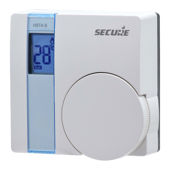
- Page 1 HRT4-B User and Installation Instructions Battery Operated Electronic Room Thermostat with Load Compensation (LC) Temperature Control Software...
- Page 3 The HRT4-B will only operate when 2 x AAA batteries have been fitted and the thermostat is wired into your central heating system.
-
Page 4: For The User
FOR THE USER What is a room thermostat? ... an explanation for householders A room thermostat simply switches the heating system on and off as necessary. It works by sensing the air temperature, switching on the heating when the air temperature falls below the thermostat setting, and switching it off once this set temperature has been reached. - Page 5 The way to set and use your room thermostat is to find the lowest temperature setting that you are comfortable with, and then leave it alone to do its job. The best way to do this is to set the room thermostat to a low temperature - say 18°C - and then turn it up by one degree each day until you are comfortable with the temperature.
-
Page 6: Additional User Information
ADDITIONAL USER INFORMATION The HRT4-B thermostat uses the latest control technology to provide extremely accurate temperature control which will help to keep your energy usage as low as possible without affecting your comfort levels. In... - Page 7 USER INSTRUCTIONS The display will show the required temperature setting and can be adjusted in increments of 1°C. To adjust the required temperature setting turn the dial anti clockwise to decrease it and clockwise to increase it. When the thermostat is in the ‘call for heat’ condition a flame symbol will appear in the display.
- Page 8 Battery Replacement The HRT4-B runs on 2 x type AAA (Alkaline) non rechargeable batteries and is designed to give a battery life of approximately two years. When the batteries are nearing the end of their life a low battery symbol will appear in the display and the batteries should be changed within a few days.
-
Page 9: Installation Instructions
Positioning the Room Thermostat The HRT4-B should be mounted on an internal wall approximately 1.5 metres from floor level and should be in a position away from draughts, direct heat and sunlight. Ensure that there will be enough space to allow easy access to the two retaining screws located at the base of the wall plate. - Page 10 N.B. The wall plate must not be altered or modified as it has been specially designed to isolate the mains supply when the thermostat is removed to change the batteries. Remove the old batteries and replace them with two new AAA size alkaline batteries ensuring that they are fitted correctly as indicated by the terminal markings in the battery compartments.
- Page 11 Once the wall plate has been removed from the packaging please ensure the HRT4-B is re-sealed to prevent damage from dust, debris etc. The wall plate should be fitted with the wiring terminals located at the top and in a position which allows a total clearance of at least 50mm around the HRT4-B thermostat.
- Page 12 Direct Wall Mounting Offer the plate to the wall in the position the HRT4-B is to be mounted and mark the fixing positions through the slots in the wall plate. Drill and plug the wall, then secure the plate in position. The slots in the wall plate will compensate for any misalignment of the fixings.
- Page 13 The wall plate is provided with a terminal guard to protect the user when replacing the batteries. This is supplied with the wall plate and it is essential that the terminal guard is fitted after completing the electrical connections to the terminals of the wall plate.
- Page 14 HRT4-B Thermostat – Internal Wiring Diagram The HRT4-B is double insulated and does not require an earth connection, an earth connection block is provided on the wall plate for terminating any cable earth conductors. Earth continuity must be maintained and all bare earth conductors must be sleeved.
- Page 15 Typical combination boiler installation for boiler with built in timer and external room ‘stat This diagram is schematic and should be used for guidance only.
- Page 16 Typical combination boiler installation with ChannelPlus H11XL time switch and HRT4-B room thermostat This diagram is schematic and should be used for guidance only.
- Page 17 Fully Pumped Heating System using HRT4-B room stat, cylinder stat and Three Port Mid Position Valve with a ChannelPlus H21/H27 electronic programmer. This diagram is schematic and should be used for guidance only.
- Page 18 Fully Pumped Heating System using HRT4-B room stat, cylinder stat and Two (2 Port) Spring Return Valves with auxiliary switches and a ChannelPlus H21/H27 electronic programmer. This diagram is schematic and should be used for guidance only.
- Page 19 Ensure that the electricity supply to the HRT4-B is switched OFF. Swing the thermostat into position on the wall plate without fitting the battery terminal guard. Tighten the 2...
- Page 20 Now switch ON the electrical circuit to the HRT4-B and observe that it switches the heating system On and Off as the temperature is turned up and down on the thermostat. If the thermostat is switching the heating system satisfactorily then switch the electricity supply...
- Page 21 Wiring conversion charts Replacing Existing Thermostats HRT4-B DRT1 Common Common Call (N/O) Satisfied (N/C) Replacing other Thermostats HRT4-B Drayton Danfoss Honeywell Digistat + RETB DT90E Common Call (N/O) Satisfied (N/C)
- Page 22 DIL Switch Settings – LC Temperature Control Software Thermostats using LC control algorithms will reduce the temperature swing that normally occurs when using traditional bellows or thermally operated thermostats. As a consequence, an LC regulating thermostat will maintain the comfort level far more efficiently than any traditional thermostat.
- Page 23 Temperature accuracy +/- 0.5°C Contact type Micro disconnection Volt free changeover Dimensions 86mm x 86mm x 36.25mm Pollution control Degree2 Design standard BS EN/EN (60730 – 2-9) Temperature range HRT4-B 5-30°C Rated Impulse voltage Cat 2 - 2500v Enclosure protection IP30...
- Page 24 Secure Meters (UK) Ltd Secure House, Lulworth Close, Chandler's Ford, NP0 0 8 3 8 4 7 0 0 0 Eastleigh, SO53 3TL, UK t: +44 1962 840048 f: +44 1962 841046 www.securemeters.com Leaflet number P83847 - Issue 7...
Need help?
Do you have a question about the HRT4-B and is the answer not in the manual?
Questions and answers