Table of Contents
Advertisement
Quick Links
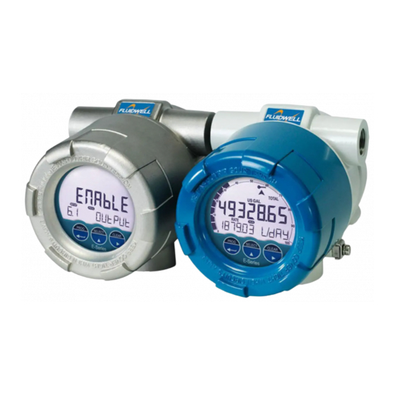
E112-P
FLOW LOGGER / TOTALIZER
with linearization, analog and pulse outputs
Signal input:
Flowmeter - type P: Pulse, NAMUR and coil
Signal outputs:
Analog referenced linearized flowrate
Scaled or unscaled pulse referenced total
Remote control:
External reset with clear-lock
Options:
Modbus communication, USB communication
E-Series - Explosion proof indicators for hazardous areas
More info: www.fluidwell.com/eseries
Advertisement
Table of Contents

Related Manuals for Fluidwell E112-P


Summary of Contents for Fluidwell E112-P
- Page 1 Flowmeter - type P: Pulse, NAMUR and coil Signal outputs: Analog referenced linearized flowrate Scaled or unscaled pulse referenced total Remote control: External reset with clear-lock Options: Modbus communication, USB communication E-Series - Explosion proof indicators for hazardous areas More info: www.fluidwell.com/eseries...
-
Page 2: Table Of Contents
E112-P TABLE OF CONTENTS ABOUT THIS MANUAL......................How to use this manual ....................Use of pictograms ......................Warranty and technical support ..................Model Reference ......................SAFETY ............................ Personal safety ....................... End-user responsibilities....................Potential equipment damage ..................Disposal of electronic waste ................... - Page 3 E112-P Handling the E-Series enclosure ..................37 6.2.1 Main parts ........................37 6.2.2 Identification........................38 6.2.3 Opening, assembling and closing the unit ..............39 6.2.4 Test unit .......................... 40 Mechanical installation....................41 6.3.1 Installation precautions ....................41 6.3.2 Mechanical dimensions ....................42 6.3.3...
-
Page 4: About This Manual
● incorrect functioning of the unit or connected instruments. A note informs you of important information. WARRANTY AND TECHNICAL SUPPORT For warranty and technical support on your Fluidwell products, visit our internet site www.fluidwell.com or contact us at support@fluidwell.com. MODEL REFERENCE Hardware version: 13.03.xx... -
Page 5: Safety
E112-P SAFETY PERSONAL SAFETY ● Explosion hazard: Never open the unit when explosive atmosphere is present, and the unit is connected to a power supply or consuming device like the internal battery supply. ● Risk of electric shock: Only open the unit if all leads are free of potential electrical energy. -
Page 6: Introduction
INTRODUCTION SYSTEM DESCRIPTION The flowrate indicator / totalizer model E112-P (also referred to as a unit) is an explosion proof microprocessor-driven instrument designed to linearize the flowmeter’s flow curve and to show the current flowrate, the totalized flow and the accumulated totalized flow, current and previous day total, and several historical day totals. -
Page 7: Product Features
● One flowmeter with a passive or active pulse, NAMUR or coil signal output can be connected to the E112-P. Several options are available for powering the sensor. ● Status input to reset total remotely or to lock the ‘clear total’ key. -
Page 8: Installation Example
E112-P INSTALLATION EXAMPLE Following parts can be recognized in below installation example. Fig. 3: Installation example E112-P 1. Cover 4. Display 7. Grounding 2. Armed cable connection 5. Optical touch keys 8. Labels 3. Pipe mounting plate 6. Process mount 9. USB connection (option) -
Page 9: Operation
Section 2: Safety [»5] INTRODUCTION This chapter describes the daily use and operation of the E112-P. For this, the unit is equipped with a control panel that provides the operator with various functions, information and operating modes. 4.1.1... -
Page 10: Optical Keys
E112-P The display contains one line with large digits at the top and one line with small digits at the bottom. The top line is mainly used to display key process information, while the bottom line usually displays less important information or system messages. -
Page 11: Backlight
E112-P The Key lock symbol appears on the display to indicate that the keys are locked or disabled: Fig. 5: Key lock symbol To unlock the optical keys, an unlock sequence needs to be performed. Start the unlock sequence by activating any of the optical keys. The display will now prompt the operator to activate each optical key in sequence: PROG >... -
Page 12: Selecting Displayed Information
E112-P 4.3.2 SELECTING DISPLAYED INFORMATION By pressing the SELECT-key, all relevant information can be reviewed on the display. When no key is pressed for 20 seconds, the display will jump back to the main screen. The following image of the display shows the main screen with Total shown on the top line and Flowrate on the bottom line. -
Page 13: Displayed Information
E112-P ● If a password is assigned in , the operator is prompted to SETUP 1.5: TOTAL > CLEAR PASSWORD [»24] enter the password before Total can be reset. ● Type IB – External reset allows to clear Total via an external pushbutton. This clear action operates in parallel with the clear total procedure of the control panel but does not require any extra confirmation or password. -
Page 14: Operator Alarms
E112-P Historical day totals Besides directly reviewing the Current Day Total and Previous Day Total, a list of the last 15 Previous Day Totals is saved. TOTAL Fig. 7: Example of historical day total from 8 days ago The list can be reviewed in LOG-mode in the following way: 1. -
Page 15: Internal Error
E112-P 4.5.2 INTERNAL ERROR When an internal error occurs, the alarm flag starts flashing to indicate this. If the alarm flag shows because of an internal error, the alarm code can be displayed by pushing the SELECT-key repeatedly until the internal alarm screen is shown. - Page 16 E112-P 4. When the desired record is selected, press PROG-key again to review the details of the record. Use the SELECT- and CLEAR-keys to scroll through the data in the record, indicated by a letter- suffix behind the record number (for example 1234.A à 1234.B à 1234.C à 1234.A).
-
Page 17: Configuration
This chapter describes how technicians can use configuration settings to configure the unit for optimal functionality. Configuration of the E112-P can be done through: ● SETUP-mode using the optical keys (with cover installed) ● SETUP-mode using the mechanical keys (push buttons) (without cover) ●... -
Page 18: Configuring Using Pc Configuration Tool
E112-P 5.2.1 CONFIGURING USING PC CONFIGURATION TOOL Configuration of the E112-P can be done using a PC with our free of charge Remote Configuration Tool software. Consult for details. Connection to a PC is Section D: Remote Configuration Tool [»71] made by means of the communication port, located at the back side of the MEM. -
Page 19: Saving Battery Lifetime (Type Pb)
E112-P Fig. 16: Disable switch for optical keys Use this switch to permanently disable the optical keys: ● Enable: move to the right / ON position. ● Disable: move to the left / OFF position. 5.2.4 SAVING BATTERY LIFETIME (TYPE PB) In case of a battery powered application, lifetime of the battery is an important subject. -
Page 20: Changing Configuration Settings
E112-P The following image shows the layout of the menu structure: SELECT CLEAR PROG CLEAR Fig. 17: SETUP menu layout and navigation Navigate the SETUP menu with the following functions: PROG-key When a menu item is selected (e.g. 1.1), this key is used to start the programming sequence. -
Page 21: Returning To Operator Mode
E112-P SELECT-key + CLEAR-key SELECT CLEAR The combination of the SELECT-key and CLEAR-key is used to select a negative value. When a value can also be entered as a negative number, pressing the SELECT- key and CLEAR-key simultaneously will toggle the ‘–‘ (minus) sign on and off. - Page 22 E112-P DISPLAY DEFAULT FUNCTION total, flowrate, acc. total total DAY TOTALS off, operate, hidden LCD NEW fast, 1 sec, 3 secs, 15 secs, 30 secs, off 1 sec BACKLIGHT 0%, 20%, 40%, 60%, 80%, 100% 100% (BRIGHTNESS) BARGRAPH enable, disable...
-
Page 23: Setup Menu Explanations
E112-P For E112-P without data logging (without type ZL) OTHERS (WITHOUT TYPE ZL) DEFAULT MODEL SOFTWARE VERSION xx.xx.xx SERIAL NUMBER xxxxxxx TIME 00:00:00 - 23:59:59 (hh.mm.ss) 00:00:00 0000 - 9999 (0000 = off) 0000 PASSWORD KEY LOCK enable, disable enable... -
Page 24: Menu 2: Flowrate
E112-P TOTAL K-FACTOR This value is used to convert the flowmeter pulse signals into a total unit. The K-Factor is based on the number of pulses generated by the flowmeter per selected measurement unit, as defined in 1.1: TOTAL > UNIT The more accurate the K‑Factor, the more accurate the system. -
Page 25: Menu 3: Display
E112-P FLOWRATE TIME Determines the time interval (sec, min, hour or day) for calculating the flowrate. Determines the number of decimals for the flowrate. DECIMALS K-FACTOR This value is used to convert the flowmeter pulse signals to a flowrate unit. The K-factor is based on the number of pulses generated by the flowmeter per measurement unit selected in 2.1: FLOWRATE >... -
Page 26: Menu 4: Flowmeter
5.5.4 MENU 4: FLOWMETER To simplify the configuration of the Flowmeter, Total and Flowrate settings, the E112-P has an automatic unit conversion feature. To use this feature, you only have to enter the average K-factor and the related measurement unit. - Page 27 E112-P Use the following procedure to set up the automatic unit conversion: : Select the correct type of flowmeter signal. 4.1: FLOWMETER > SIGNAL : Select the type of measurement unit (volume or mass) shown on the 4.2: FLOWMETER > UNITS certificate.
-
Page 28: Menu 5: Linearization
E112-P FLOWMETER UNITS This setting activates the automatic unit conversion function which converts the selected flowmeter unit to measurement units for Total and Flowrate. The following can be selected: Auto-vol: Automatic unit conversion is enabled for volumetric flow. ● Flowmeter, Total and Flowrate show volumetric measurement units. - Page 29 E112-P K-Factor KF0=51.64178 KF1=35.7 @ 64Hz. MF1=0.691300 KF2=47.5 @ 93Hz. MF2=0.919798 KF3=53.8 @ 161Hz. MF3=1.041792 KF4=49.2 @ 336Hz. MF4=0.952717 KF5=52.9 @ 514Hz. MF5=1.024364 51.6 35.7 Frequency 64 93 10,000 Fig. 18: Example of K-Factors and linearization points When a new frequency is measured, the corresponding Meter Factor is calculated by interpolating between the linearization points.
-
Page 30: Menu 6: Analog Output
E112-P LINEARIZATION 5.1...F FREQ. / M-FACTOR The list with linearization entries of the flowmeter is entered here. The 1 ... 15 entries can be entered in random order, although ascending order is advised for easier verification. Each entry shows the following: M-Factor: Displayed on the top line of the display. -
Page 31: Menu 7: Pulse Output
E112-P ANALOG OUTPUT CUT-OFF A low flow cut-off can be set as a percentage of the full range of 16 mA, for example, to ignore leakage. When the flow is less than the required rate, the current will be the minimum signal (4 mA, or 20mA when the analog output is programmed ‘up-side-down’). -
Page 32: Menu 8: Modbus Communication
SELECT-key, then press the CLEAR key to set the digits. 5.5.8 MENU 8: MODBUS COMMUNICATION The E112-P can optionally be equipped with a communication interface that uses the Modbus protocol (Type CB/CH/CU). See for a detailed explanation Section C: Modbus communication [»64] of the protocol, data types, and available registers. -
Page 33: Menu 9: Others (Without Type Zl)
NONE, EVEN, ODD 5.5.9 MENU 9: OTHERS (WITHOUT TYPE ZL) When the E112-P is ordered with the datalogging option (type ZL), this menu is replaced by the menus described in Menu 9: Datalogging (with type ZL) [»33] Menu 10: Others (with type ZL) [»35]... - Page 34 E112-P Daily records The daily log records the daily record in the Daily logbook. This is done at one or two predetermined time(s) in the day; for example, before or at the end of a so called contract hour. This function can be used to determine the total of the previous contract hour, or trend the total over a certain period of time.
-
Page 35: Menu 10: Others (With Type Zl)
E112-P DATALOGGING (WITH TYPE ZL) LOG INTERVAL Selects the interval at which an interval record is created. The interval log logbook can hold up to 1000 records. When it is full, it will overwrite the oldest record first. DAILY LOG Selects how many times a day a daily record is created. -
Page 36: Installation
Personnel must read and understand this Operating Manual before carrying out its instructions. ● The E112-P may only be operated by personnel who are authorized and trained by the operator of the facility. All instructions in this manual are to be observed. -
Page 37: Handling The E-Series Enclosure
E112-P HANDLING THE E-SERIES ENCLOSURE 6.2.1 MAIN PARTS Fig. 21: Exploded view 1. Cover 5. Body 2. Main Electronics Module (MEM) 6. Grounding terminal 3. Battery 7. Label 4. Supply Module (RSM or BSM) Fig. 22: Main Electronic Module and two types of Supply Module (BSM, RSM) 1. -
Page 38: Identification
WALL. OTHERWISE, SEAL ALL CONDUITS WITHIN 18 INCHES. ATEX, IECEx, CSA GROUPE A: SCELLEZ LES ENTRÉES AU DROIT DE L'ENVELOPPE. SINON, SCELLEZ TOUTES LES ENTRÉES DE CONDUITS À 18 INCHES MAX. Additional information Fluidwell BV, Voltaweg 23, Veghel, The Netherlands. Mfg.Date: 2023 Fig. 23: Configuration label... -
Page 39: Opening, Assembling And Closing The Unit
E112-P Depending on product type, the optional Supply Module (RSM or BSM) is also labeled: XX000000-X00-0000-0000 Batt. conn. Only use factory supplied battery, spare part nr. SPB02. Fire, explosion or severe burns may result if mistreated. Do not recharge, crush, disassemble, incinerate, heat above 100°C (121°F) or expose contents to water. -
Page 40: Test Unit
E112-P Re-assembling the unit 1. If applicable: check that the battery is correctly inserted and connected to the supply module (BSM / RSM). See Section 7.3: Battery replacement instructions [»55] 2. If applicable: plug the cable connectors with connected wiring into the RSM. -
Page 41: Mechanical Installation
Connecting enclosures and mounting on flowmeters The E112-P may be connected to another certified enclosure under following conditions: ● The connected enclosure is certified for the used type of protection and certified for its own internal electrical equipment (i.e. pickup coil or other sensors). -
Page 42: Mechanical Dimensions
E112-P 6.3.2 MECHANICAL DIMENSIONS 112mm / 4.41” Left connection Right connection M20x1.5 M20x1.5 M25x1.5 M25x1.5 ½” NPT ½” NPT ¾” NPT ¾” NPT Bottom connection M20x1.5 M25x1.5 ½” NPT ¾” NPT 1” NPT 70mm / 2.76” 148mm / 5.83” Fig. 28: Mechanical dimensions of the E-Series enclosure 6.3.3... - Page 43 E112-P When mounting the unit, leave the cover on as much as possible to prevent damage to the thread winding. Only remove cover and MEM after mounting. The following options are available to mount the unit: ● Directly on a panel.
-
Page 44: Electrical Installation
E112-P Mount unit on a wall 1. Use the wall mount accessories (ACE03) to attach the unit as shown and follow the Assembly Instructions as supplied with the accessory. 2. Remove the cover and the MEM (see Section 6.2.3: Opening, assembling and closing the unit [»39]... -
Page 45: Grounding Of The Enclosure
E112-P Electrical precautions ● Ensure the unit is correctly wired according to the wiring diagrams and complies with local codes and regulations. ● A suitable power supply should be considered in end-use equipment to power the unit. This supply should comply with a limited-energy circuit (maximum available current of 8 A) such as a “SELV”... -
Page 46: Electrical Ratings
E112-P 6.4.3 ELECTRICAL RATINGS Power supply (Type AH, PX, PD) The following supply ratings apply to the E-Series when the indicated options are installed (other options have negligible influence on the ratings) and should be used to select a suitable power... -
Page 47: Terminal Connectors - Mem
E112-P Type PD: Sensor supply: 8.2 VDC – 12 VDC or 24 VDC (Vin P2 minus 1 V) This option provides a supply derived from the input supply. Adjust the P3 output voltage using switches J1 and J2 on the bottom rear of the MEM (Main Electronics Module) - see following figure. -
Page 48: Terminal Connectors - Rsm
E112-P SENSOR LOOP POWERED SENSOR INPUT SUPPLY RESET INPUT COMMUNICATION ANALOG OUTPUT IB: Reset total/Clear-lock CB: RS232 AH: Isolated 4 - 20mA P: coil 8.2 / 12 / 24V +12V P: reed switch / NPN CH: RS485 - 2 wire Note: Non-polarity sensitive. -
Page 49: Terminals R1-R2 And R10-R11: Digital Outputs D1 And D5
E112-P 6.4.9 TERMINALS R1-R2 AND R10-R11: DIGITAL OUTPUTS D1 AND D5 The functionality of the digital output is programmed through SETUP 7: PULSE OUTPUT [»32] ● The digital output D1 has a maximum frequency of 500Hz for scaled pulse and 10kHz for pulse retransmission. - Page 50 E112-P The sensor output should match with the selected flowmeter setting of SETUP 4: FLOWMETER [»27] Sine-wave signal (Coil) The unit can be used with flowmeters which have a coil output signal. Two sensitivity levels can be selected (see SETUP 4: FLOWMETER [»27] ●...
- Page 51 E112-P Power supply type PD provides a sensor supply voltage of 8.2, 12, or 24 VDC. ↓ J1-J2 8.2 ; 12V; 24V ↓ PNP-LP* ┴ Common system ground Fig. 38: Terminals S1-S3 and P3: Pulse signal input PNP Reed switch The unit can be used with flowmeters which have a reed switch. To avoid pulse bounce from the reed switch, it is advised to select REED LP –...
-
Page 52: 6.4.11 Terminals E1-E2: External Reset With Clear-Lock - Type Ib
E112-P Active signals 8.2 V and 24 V The unit is suitable for flowmeters with an Active signal. The detection levels are about 50% of the selected supply voltage; approximately 4 V (ACT_8.1) or 12 V (ACT_24). See SETUP for more information. -
Page 53: 6.4.12 Terminals C1-C4: Communication Rs232/Rs485/Usb - Type Cb/Ch/Cu
E112-P 6.4.12 TERMINALS C1-C4: COMMUNICATION RS232/RS485/USB - TYPE CB/CH/CU ● Serial communications are possible on hardware layers RS232 (length of cable max. 5 meters), RS485 (length of cable max. 1200 meters) and USB (length of cable max. 5 meters). To achieve reliable communication, make sure the hardware layer specific requirements are met. -
Page 54: 6.4.13 Terminals A1-A2: Isolated Analog Output - Type Ah
E112-P 6.4.13 TERMINALS A1-A2: ISOLATED ANALOG OUTPUT – TYPE AH The flowrate proportional output (AH) is standard available. This output is an isolated 4-20 mA output with the possibility to power the device via the 4-20 mA loop. It is non-polarity sensitive. -
Page 55: Maintenance
) before proceeding. Section 2: Safety [»5] If the E112-P is damaged or faulty, it cannot be repaired by the user and must be replaced with an equivalent certified product. Repairs can only be carried out by the manufacturer or their authorized agent. -
Page 56: Supply Battery Replacement
à plus de 100°C (212°F) ou exposer à l'eau. Primary Lithium Battery - Only replace with Fluidwell recommended battery pack! Pile primaire au lithium - Remplacer uniquement par une pile recommandé par Fluidwell! Fig. 45: Marking supply battery: StdLiBAT021 (SPB02) Remove the old battery as follows: 1. -
Page 57: Replace Silica Gel Sachet
E112-P Install the new battery as follows: 1. Unpack the new battery and ensure there are no signs of damage. 2. Press the battery, with the + side upwards, fully into the battery holder as shown. 3. Carefully click the back cover into its original position on the MEM. -
Page 58: Appendix A - Technical Specification
E112-P APPENDIX A - TECHNICAL SPECIFICATION GENERAL DISPLAY Type High intensity numeric and alphanumeric LCD, UV-resistant, with adjustable bright backlight Digits Seven 12 mm (0.47”) and eleven 7 mm (0.28”). Various symbols and measuring units. Dimensions Ø 65 x 45 mm (2.56” x 1.77”) Refresh rate User definable: 8 times/sec –... -
Page 59: Input
E112-P DATA PROTECTION Backup EEPROM backup of all settings (running totals every minute; data retention at least 10 years) Password Configuration settings can be password protected INPUT FLOWMETER Type P Coil / sine wave (COIL-HI: 20 mVpp or COIL-LO: 90 mVpp sensitivity selectable), NPN, PNP,... -
Page 60: Operational
E112-P OPERATIONAL OPERATOR FUNCTIONS Displayed information Linearized flowrate, total and accumulated total ● Current day total, previous day total and 15 historical day totals ● Indicating speedometer for flowrate ● Reviewing historical day totals or reviewing the various logbooks (Type ZL) ●... - Page 61 E112-P HAZARDOUS AREA CLASSIFICATION ATEX Certificate: DEKRA 14ATEX0006 Gas: II 2 G Ex db IIC T6 Gb Dust: II 2 D Ex tb IIIC T85°C Db X IECEx Certificate: IECEx DEK 14.0001X Gas: Ex d IIC T6 Gb Dust: Ex tb IIIC T85°C Db...
-
Page 62: Appendix B - Troubleshooting
E112-P APPENDIX B - TROUBLESHOOTING Table 1 lists and describes how to troubleshoot problems that can occur when installing or operating the unit. Table 2 lists internal alarm codes and conditions signaled by a blinking ALARM icon on the display. The alarm code can be displayed by pushing the SELECT-key repeatedly until the ALARM internal alarm screen is shown. - Page 63 E112-P Table 2: Internal alarms When multiple alarms occur, the error code shown is the sum of the error codes as given below. For example 0048 is a combination of error code 0016 and 0032. To find out which error codes are present at the same time, register the number shown on the display and decode the errors as follows: ●...
-
Page 64: Appendix C - Modbus Communication
E112-P APPENDIX C - MODBUS COMMUNICATION INTRODUCTION The product is fitted with the Modbus communication protocol and can be equipped with various physical interfaces like RS485 and RS232 (please see device datasheet for available options). The tables below show the various variables that can be accessed through the communication. -
Page 65: Runtime Variables Of The Unit
Representation: unit, decimals depending on variables 32, 33 Note: The list of runtime variables shown above can be read as one contiguous list of registers. Unused registers return 0. RUNTIME VARIABLES OF THE E112-P - FLOATING POINT BASED 32 BIT – CONTIGUOUS READ HOLDING NO. -
Page 66: Configuration Variables Of The Unit
E112-P RUNTIME VARIABLES OF THE E112-P - FLOATING POINT BASED 32 BIT – CONTIGUOUS READ [d] 6404 46405 accumulated float32 0... 99999999999 [h] 0x1904 total Representation: unit depending on variable 32 [d] 6406 46407 flow rate float32 0... 9999999 [h] 0x1906... - Page 67 E112-P MODBUS-REGISTERS: TOTAL [d] 47 40048 multiply factor uint16 0=x1 1=x10 2=x100 3=x1000 [h] 0x002F [d] 1052 41053 clear total uint16 000...999 [h] 0x041C password Setting 000 disables the clear total password feature. [d] 2146 42147 contract hour uint16 0...23 Hour...
- Page 68 E112-P MODBUS-REGISTERS: FLOWMETER [d] 1050 41051 K-factor unit uint16 0=none 3=US GAL 6=OilBBL 9=LB [h] 0x41A 4=I GAL 7=kg 10=US ton 5=CF 8=ton [d] 1046 41047 K-factor uint32 1…9999999 [h] 0x416 Representation: 0.000010…9999999 depending on variable 54: decimals K-factor [d] 1049...
- Page 69 E112-P MODBUS-REGISTERS: PULSE OUTPUT [d] 133 40134 pulse quantity uint16 0…3 [h] 0x085 decimals MODBUS-REGISTERS: MODBUS COMMUNICATION HOLDING NO. OF VARIABLE TYPE VALUES / REPRESENTATION / REMARKS ADDRESS REGISTER REG’S [d] 144 40145 speed uint16 0=1200 2=4800 4=9600HP 6=38400 [h] 0x090...
- Page 70 E112-P MODBUS-REGISTERS: OTHERS [d] 176 40177 time (local) uint32 00:00:00…23:59:59 [h] 0x0B0 Representation: hh:mm:ss Stored decimal: 23:59:59 = 235959d = 0x0003.99B7 [d] 168 40169 password uint16 0000…9999 [h] 0x0A8 Representation: 4-digit number, 0000 means off. [d] 139 40140 keyboard lock...
-
Page 71: Appendix D - Remote Configuration Tool
E112-P APPENDIX D - REMOTE CONFIGURATION TOOL INTRODUCTION The free PC software can be downloaded and installed onto your computer system. The software package allows you to set the configurations as desired, up- or download the settings to the MEM and print a hardcopy for each product. -
Page 72: Download And Install
DOWNLOAD AND INSTALL The Remote Configuration Tool software package can be downloaded from our website at www.fluidwell.com/software and installed using the installation program. The installation also contains a Quickstart manual which gives detailed instructions on how to achieve a successful connection between PC and MEM. -
Page 73: Appendix E - Legal Information
Co nfo mity Fluidwell E Series indicators ‒ he , January 2023 We, Fluidwell BV, declare under our s e ol respons ibility that the ‒ E Series indicators are designed and will operate conform the following applicable European Directives and Harmonised Standards, when... - Page 74 E112-P NOTES Page 74 FW_E112-P_M_v0302-02_EN...
- Page 75 E112-P FW_E112-P_M_v0302-02_EN Page 75...
- Page 76 Fluidwell bv P.O. Box 6 Voltaweg 23 Website: www.fluidwell.com 5460 AA Veghel 5466 AZ Veghel Find your nearest representative: www.fluidwell.com/representatives the Netherlands the Netherlands © Copyright 2023 - FW_E112-P_M_v0302-02_EN...
Need help?
Do you have a question about the E112-P and is the answer not in the manual?
Questions and answers