Sign In
Upload
Manuals
Brands
Fluidwell Manuals
Measuring Instruments
E112
Fluidwell E112 Manuals
Manuals and User Guides for Fluidwell E112. We have
1
Fluidwell E112 manual available for free PDF download: Manual
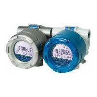
Fluidwell E112 Manual (76 pages)
FLOW LOGGER/TOTALIZER with Linearization, Analog and Pulse Outputs
Brand:
Fluidwell
| Category:
Measuring Instruments
| Size: 3 MB
Table of Contents
Table of Contents
2
About this Manual
4
How to Use this Manual
4
Use of Pictograms
4
Warranty and Technical Support
4
Model Reference
4
Safety
5
Personal Safety
5
End-User Responsibilities
5
Potential Equipment Damage
5
Disposal of Electronic Waste
5
Introduction
6
System Description
6
Product Features
7
Installation Example
8
Operation
9
Introduction
9
Operating Modes
9
Control Panel
9
Display
9
Optical Keys
10
Backlight
11
Operator Functions
11
Functions of the Keys in Operator Mode
11
Selecting Displayed Information
12
Clearing Total
12
Displayed Information
13
Flowrate
13
Total and Accumulated Total
13
Current Day Total and Previous Day Total
13
Operator Alarms
14
Low Battery
14
Internal Error
15
Datalogging (with Type ZL)
15
Configuration
17
Introduction
17
Operating the Main Electronics Module (MEM)
17
Configuring Using PC Configuration Tool
18
Mechanical Keys
18
Optical Keys Switch
18
Saving Battery Lifetime (Type PB)
19
Configuring Using SETUP Mode
19
Entering SETUP Mode
19
Navigating the SETUP Menu
19
Changing Configuration Settings
20
Returning to Operator Mode
21
SETUP Menu Overview
21
SETUP Menu Explanations
23
Menu 1: Total
23
Menu 2: Flowrate
24
Menu 3: Display
25
Menu 4: Flowmeter
26
Menu 5: Linearization
28
Menu 6: Analog Output
30
Menu 7: Pulse Output
31
Menu 8: Modbus Communication
32
Menu 9: Others (Without Type ZL)
33
Menu 9: Datalogging (with Type ZL)
33
Menu 10: Others (with Type ZL)
35
Installation
36
Installation / Environmental Conditions
36
Handling the E-Series Enclosure
37
Main Parts
37
Identification
38
Opening, Assembling and Closing the Unit
39
Test Unit
40
Mechanical Installation
41
Installation Precautions
41
Mechanical Dimensions
42
Mounting the Unit
42
Electrical Installation
44
Electrical Precautions
44
Grounding of the Enclosure
45
Electrical Ratings
46
Voltage Selection Sensor Supply
46
Terminal Connectors - MEM
47
Terminal Connectors - RSM
48
Terminals P1-P2 or P5-P6: Power Supply - Type PD/PX
48
Terminals P3: Sensor Supply - Type PD
48
Terminals R1-R2 and R10-R11: Digital Outputs D1 and D5
49
6.4.10 Terminals S1-S3: Flowmeter Input
49
6.4.11 Terminals E1-E2: External Reset with Clear-Lock - Type Ib
52
6.4.12 Terminals C1-C4: Communication Rs232/Rs485/Usb - Type Cb/Ch/Cu
53
6.4.13 Terminals A1-A2: Isolated Analog Output - Type Ah
54
Maintenance
55
Check for Wear or Damage
55
Clean Unit
55
Battery Replacement Instructions
55
Supply Battery Replacement
56
Clock Battery Replacement
56
Replace Silica Gel Sachet
57
Appendix A - Technical Specification
58
General
58
Input
59
Output
59
Operational
60
Standards and Approvals
60
Appendix B - Troubleshooting
62
Appendix C - Modbus Communication
64
Introduction
64
Runtime Variables of the Unit
65
Configuration Variables of the Unit
66
Appendix D - Remote Configuration Tool
71
Introduction
71
Cable Connection
71
Download and Install
72
Appendix E - Legal Information
73
Declaration of Conformity
73
Advertisement
Advertisement
Related Products
Fluidwell E112-P
Fluidwell E115-P
Fluidwell E126-P-EG
Fluidwell E126-P-EL
Fluidwell E119-P
Fluidwell E119
Fluidwell E110 Series
Fluidwell E115
Fluidwell E126-EL
Fluidwell E126-EG
Fluidwell Categories
Measuring Instruments
Controller
Monitor
Touch Panel
Desktop
More Fluidwell Manuals
Login
Sign In
OR
Sign in with Facebook
Sign in with Google
Upload manual
Upload from disk
Upload from URL