Advertisement
NCP6951EVK
Camera PMIC with Flash
LED Driver Evaluation Board
User's Manual
Overview
The NCP6951EVK evaluation kit is a full assembled
circuit board for evaluation and test of the NCP6951. This
document provides documentation, test procedure and
equipment set−up for the complete evaluation of the
NCP6951.The NCP6951EVK comes with one NCP6951
evaluation board, 1 MCU board for I
associated cables.
General Description
The
NCP6951 integrated circuit is part of the
ON Semiconductor mini power management IC family. It is
optimized to supply battery powered portable application
sub−systems such as camera function, microprocessors, etc.
This device integrates one high efficiency 600 mA
Step−down DCDC converter with DVS (Dynamic Voltage
Scaling), 5 low dropout (LDO) voltage regulators and a
1.5 A Flash LED driver in WLCSP24 package.
Features
•
1 Flash LED Driver
Adaptive Boost Supply or Bypass Mode depending
♦
on V
and V
Conditions
in
flash
Programmable Flash Current from 100 mA to 1.6 A
♦
by 100 mA Steps
Programmable Safety and Inhibit Timer to Limit the
♦
Flash Duration and Protect the Application
© Semiconductor Components Industries, LLC, 2015
July, 2015 − Rev. 1
2
C master and
•
1 DC−DC Converters (3 MHz, 1 mH / 10 mF, 600 mA)
♦
♦
•
5 Low Noise − Low Dropout Regulators
♦
♦
♦
♦
♦
•
Control
♦
•
Small Footprint: 2.57 x 1.65 mm WLCSP 0.4 mm Pitch
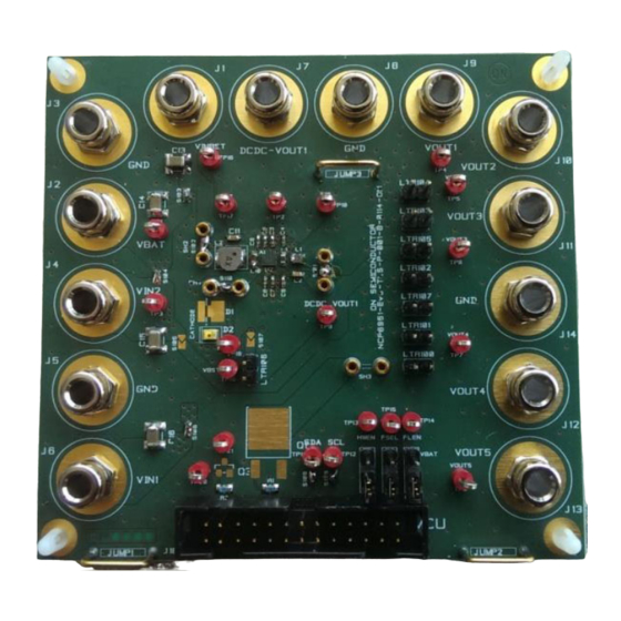
Figure 1. Evaluation Board Picture
1
www.onsemi.com
EVAL BOARD USER'S MANUAL
Peak Efficiency 95%
Programmable Output Voltage from 0.8 V to 2.3 V
by 50 mV Steps
Programmable Output Voltage from 1.7 V to 3.3 V
for LDOs 1, 2, 3
Programmable Output Voltage from 1.2 V to 2.85 V
for LDOs 4, 5
200 mA Output Current Capability: LDOs 1, 2, 3, 4
300 mA Output Current Capability LDO 5
45 mVrms Low Output Noise
Fully Programmable through a 400 kHz / 3.4 MHz
2
2
I
C with Pins Selectable I
C Address and Interrupt
Output
Publication Order Number:
EVBUM2291/D
Advertisement
Table of Contents

Related Manuals for ON Semiconductor NCP6951EVK


Summary of Contents for ON Semiconductor NCP6951EVK
- Page 1 Camera PMIC with Flash LED Driver Evaluation Board User's Manual Overview The NCP6951EVK evaluation kit is a full assembled www.onsemi.com circuit board for evaluation and test of the NCP6951. This EVAL BOARD USER’S MANUAL document provides documentation, test procedure and equipment set−up for the complete evaluation of the...
- Page 2 NCP6951EVK Table 1. BOARD COMPONENTS DESCRIPTION Reference Value PCB Footprint Part Number − NCP6951 PMIC − ON Semiconductor NCP6951 0402 C1005X5R0J225K050BC Ceramic Capacitor 2.2 mF 6.3 V X5R C3 → C9 Ceramic Capacitor 1 mF 0402 C1005X5R0J105K05BB 6.3 V X5R Ceramic Capacitor 4.7 mF...
- Page 3 NCP6951EVK Table 2. CONNECTOR DESCRIPTION Description Input Power J1 → J6 J3, J5 Negative input connected to GND pin Flash LED power supply DCDC power supply J4, J5 LDOs power supply Input Power J7 → J14 J8, J14 Negative output connected to GND pin...
-
Page 4: Assembly Layer
NCP6951EVK ASSEMBLY LAYER Figure 2. Assembly Layer www.onsemi.com... - Page 5 NCP6951EVK SCHEMATIC TP10 TP11 TP12 TP13 TP14 TP15 TP16 TP17 TP18 TP19 DCDC_VOUT1 VOUT1 VIN_BST 100uF VOUT2 S103 VBAT VOUT3 100uF VOUT4 S101 NCP6951 Ï Ï Ï C1 2.2uF VOUT5 VBAT PVIN1 DCDC_VOUT1 S104 100nF AGND Ï Ï Ï AGND...
-
Page 6: Software Installation
NCP6951EVK SOFTWARE INSTALLATION Important notice: In order to properly install drivers and Double click on NCP6951_setup.exe file. Follow the instructions set−up. software, please launch NCP6951_setup.exe file before It is recommended to copy the NCP6951_setup.exe to a connects the MCU board. -
Page 7: Quick Configuration
NCP6951EVK QUICK CONFIGURATION Power Supply Load NCP6951 requires at least 1 external power supply: DCDCx Converters Vbat (J2) : supply between 2.5V to 5.5V. An electronic load or passive load can be connected between J7 and J8 for DCDC1. Jumpers Configuration... - Page 8 NCP6951EVK Figure 6. Bottom Layer www.onsemi.com...
- Page 9 onsemi, , and other names, marks, and brands are registered and/or common law trademarks of Semiconductor Components Industries, LLC dba “onsemi” or its affiliates and/or subsidiaries in the United States and/or other countries. onsemi owns the rights to a number of patents, trademarks, copyrights, trade secrets, and other intellectual property. A listing of onsemi’s product/patent coverage may be accessed at www.onsemi.com/site/pdf/Patent−Marking.pdf.
Need help?
Do you have a question about the NCP6951EVK and is the answer not in the manual?
Questions and answers