Advertisement
Quick Links
NCP1090GEVB,
NCP1094GEVB
Power-over-Ethernet PD
Interface Evaluation Board
User's Manual
Introduction
The NCP1090GEVB and NCP1094GEVB evaluation
boards are designed to showcase the features of the
NCP109x series of Power-over-Ethernet interfaces. The
boards are designed as splitter interfaces, taking a
PoE-enabled port as input and offering the power to a
separate connector, while passing through the data to
another Ethernet port. The schematics, gerber files and
BOM of these boards are available through our website
(www.onsemi.com)
Basic Circuit Description
The evaluation boards consist of different sections that
will be described in detail in the next paragraphs. First, we
will discuss the input section, including selection of the
correct connectors, magnetics and the termination for a
Power-over-Ethernet enabled connection. In the next
section we will explain the operation of the NCP109x, the
detection and classification process, and how to configure
the NCP109x for the correct power class. Finally, we will
explain how to use the UVLO support (for NCP1091 and
NCP1093) or auxiliary support (for NCP1092 and
NCP1094).
Table 1. ELECTRICAL CHARACTERISTICS
NCP1090,
NCP1091,
Input Voltage, PoE
Input Current, PoE
Auxiliary Input Voltage
Auxiliary Input Current
© Semiconductor Components Industries, LLC, 2012
March, 2020 − Rev. 1
NCP1093,
NCP1092
NCP1094
37 V − 57 V
500 mA
680 mA
10.8 V − 57 V
0 − 5 A
EVAL BOARD USER'S MANUAL
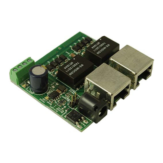
Figure 1. NCP1090GEVB Photo
Figure 2. NCP1094GEVB Photo
1
www.onsemi.com
Publication Order Number:
EVBUM2156/D
Advertisement

Related Manuals for ON Semiconductor NCP1090GEVB


Summary of Contents for ON Semiconductor NCP1090GEVB
- Page 1 User's Manual www.onsemi.com EVAL BOARD USER’S MANUAL Introduction The NCP1090GEVB and NCP1094GEVB evaluation boards are designed to showcase the features of the NCP109x series of Power-over-Ethernet interfaces. The boards are designed as splitter interfaces, taking a PoE-enabled port as input and offering the power to a separate connector, while passing through the data to another Ethernet port.
-
Page 2: Input Section
NCP1090GEVB, NCP1094GEVB INPUT SECTION Ethernet Connectors, Magnetics and Termination Output Connector Auxiliary Power Connector Ethernet Connector (out) Power−over−Ethernet Connector (in) Figure 3. Connection Diagram The NCP109x evaluation boards have 2 RJ45 connectors. output connector connected proper One connector is used as the input connector and supports Power-over-Ethernet PSE, the PD detection will fail without Power-over-Ethernet. - Page 3 NCP1090GEVB, NCP1094GEVB Figure 5. Input Section of the Evaluation Boards Termination Termination of an Ethernet port should be done on the connector side of the magnetics. The typical termination for Ethernet ports is called a ‘Bob Smith termination’ and is shown in Figure 6.
- Page 4 NCP1090GEVB, NCP1094GEVB NCP109x OPERATION Power−over−Ethernet Detection and Classification When the PSE has detected a valid PD signature, the PSE To distinguish power-over-ethernet enabled ports from will start the classification phase. During the classification regular Ethernet ports, the Power Supply Equipment (PSE) phase, the PSE will determine the power class of the PD.
- Page 5 NCP1090GEVB, NCP1094GEVB Inrush and Operational Current Limitation The pass switch is then turned completely on, and the IC When the PSE applies power to the PD after the detection switches to an operational current limit. Both limits are and classification phases, the pass switch will initially limit programmed with the same programming resistor, which is the current passing through it.
- Page 6 NCP1090GEVB, NCP1094GEVB to flow through the auxiliary resistor divider, the AUX pin we put a PNP transistor (Q1) in series, which will disable this voltage would rise above the threshold, and turn of the PoE, current path. The resulting schematic is shown in Figure 9.
- Page 7 onsemi, , and other names, marks, and brands are registered and/or common law trademarks of Semiconductor Components Industries, LLC dba “onsemi” or its affiliates and/or subsidiaries in the United States and/or other countries. onsemi owns the rights to a number of patents, trademarks, copyrights, trade secrets, and other intellectual property. A listing of onsemi’s product/patent coverage may be accessed at www.onsemi.com/site/pdf/Patent−Marking.pdf.
- Page 8 Power Management IC Development Tools Click to view products by manufacturer: ON Semiconductor Other Similar products are found below : EVAL-ADM1168LQEBZ EVB-EP5348UI MIC23451-AAAYFL EV MIC5281YMME EV DA9063-EVAL ADP122-3.3-EVALZ ADP130- 0.8-EVALZ ADP130-1.2-EVALZ ADP130-1.5-EVALZ ADP130-1.8-EVALZ ADP1712-3.3-EVALZ ADP1714-3.3-EVALZ ADP1715-3.3- EVALZ ADP1716-2.5-EVALZ ADP1740-1.5-EVALZ ADP1752-1.5-EVALZ ADP1828LC-EVALZ ADP1870-0.3-EVALZ ADP1871-0.6- EVALZ ADP1873-0.6-EVALZ ADP1874-0.3-EVALZ ADP1882-1.0-EVALZ ADP199CB-EVALZ ADP2102-1.25-EVALZ ADP2102-...
Need help?
Do you have a question about the NCP1090GEVB and is the answer not in the manual?
Questions and answers