Advertisement
EVBUM2520/D
NCP4306 Synchronous
Rectification Evaluation
Board User's Manual
Description
This evaluation board user's manual describes a high efficiency
synchronous rectification evaluation board that can easily replace a
secondary side rectification diode in an SMPS.
The NCP4306 is used as synchronous rectification controller. The
evaluation board has very few external components and illustrates
how small and effective such a design can be.
The NCP4306 features a very precise 0 mV turn−off comparator
that supports even very low current flowing through the MOSFET
even when very low RDSON synchronous MOSFETs is used.
NCP4306 can be used in application working in CCM without
external synchronization thanks to very low propagation delay and
strong driver.
Key Features
•
Precise Turn−off Comparator
•
Wide Input Voltage Range
•
High Operation Frequency
•
Strong MOSFET Driver
•
High Efficiency
•
Adjustable Minimum On and Off Times
•
Adjustable Light Load Detection Feature
•
Capable to Operate in Positive and Negative Branch
•
Small Size
Table 1.
SMPS Type
Flyback, QR
© Semiconductor Components Industries, LLC, 2017
November, 2017 − Rev. 0
Supply Voltage
3.5 − 35 V
1
www.onsemi.com
EVAL BOARD USER'S MANUAL
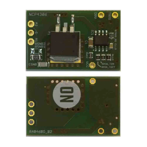
Figure 1. Evaluation Board Photo
Reverse Voltage
Effective Resistance
150 V
10 mW
Publication Order Number:
EVBUM2520/D
Advertisement
Table of Contents

Related Manuals for ON Semiconductor NCP4306


Summary of Contents for ON Semiconductor NCP4306
- Page 1 The NCP4306 features a very precise 0 mV turn−off comparator that supports even very low current flowing through the MOSFET even when very low RDSON synchronous MOSFETs is used.
-
Page 2: Connection Diagram
EVBUM2520/D CONNECTION DIAGRAM Figure 2. Possible Connections into Circuit The evaluation board can be connected in circuit where to use an external power supply (or auxiliary winding with the rectification diode is in the positive or negative branch. rectification) to provide power to the evaluation board. VCC When connection to a positive branch is used, it is necessary should be referenced to A1 or A2 points. -
Page 3: Evaluation Board Schematic
EVBUM2520/D EVALUATION BOARD SCHEMATIC Figure 3. Schematic of the NCP4306 The evaluation board was designed to support a minimal be needed to adjust them according to used SMPS. RLLD external component count implementation. C1 is sets light load detection time and CLLD is optional for LLD decoupling capacitor that should be placed as close as voltage decoupling. -
Page 4: Circuit Layout
EVBUM2520/D CIRCUIT LAYOUT The PCB consists of a 2 layer FR4 board with 35 mm and turn−off times. The same is true for the CS pin. For the copper cladding. All components are surface mount. Critical CS pin, a kelvin contact was done to be able to sense the component such as blocking capacitor C1 has to be placed voltage directly at the drain. - Page 5 EVBUM2520/D Figure 6. Top Side Components Figure 7. Bottom Side Components www.onsemi.com...
- Page 6 EVBUM2520/D Figure 8. Evaluation Board Photos www.onsemi.com...
-
Page 7: Bill Of Material
FDA Class 3 medical devices or medical devices with a same or similar classification in a foreign jurisdiction or any devices intended for implantation in the human body. Should Buyer purchase or use ON Semiconductor products for any such unintended or unauthorized...
Need help?
Do you have a question about the NCP4306 and is the answer not in the manual?
Questions and answers