Table of Contents
Advertisement
Quick Links
NCP1096GEVB
NCP1096 Evaluation Board
User's Manual
IEEE 802.3bt PoE-PD Interface Controller
Board
General
The NCP1096GEVB board allows easy implementation
and evaluation of a Power-over-Ethernet powered
equipment that is able to operate with an assigned power
level up to 90 W. The evaluation board is based on the PoE
PD Controller NCP1096 (U2) that uses an internal
pass-switch and sense resistor. The board can also facilitate
the design of proprietary 100 W+ applications.
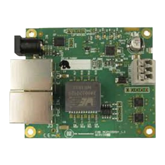
Figure 1. Operational NCP1096GEVB Showing
Basic Interconnections
The NCP1096GEVB board is designed as a PoE splitter:
having a PoE-enabled Ethernet port (labeled "PoE IN") as
input and offering the power to a separate connector (J2)
while passing through the data to another Ethernet port
(labeled "E OUT").
© Semiconductor Components Industries, LLC, 2019
July, 2019 − Rev. 1
EVAL BOARD USER'S MANUAL
Quick Start Guide
Step 1: Connect the power connections available on
connector J2 (labeled "GND" and "VPP") to the DC/DC
converter on the system that needs to be powered (cf. black
and red wires in the picture on the left). The DC/DC
converter behind the NCP1096 EVB should be operational
over a 34 V to 57 V voltage range.
Step 2: Connect the control connection to the DC/DC
converter! It is important that the DC/DC converter or
any significant load is kept off when the pass-switch is
charging the input capacitance.
For a DC−DC converter with an undervoltage (UV or
UVLO) or an active high enable (EN or SHND), the "PG"
signal on connector J2 could be used (cf. green wire in the
picture on the left). The "PG" signal will be clamped to 18 V
by a zener when the board is powered up. For some DC−DC
converter boards an additional diode in series with the
control connection might be required (cathode connected to
NCP1096 and anode connected to the DC−DC converter).
For a DC−DC converter with an active low enable (EN or
SHDN or ON/OFF), the "nPG" signal on P1 could be used.
The "nPG" signal will be pulled up to VPP during the inrush
phase. Always check the voltage rating of the enable,
shutdown or undervoltage pin of the DC−DC converter.
Step 3: Insert the Ethernet cable (cf. blue cable in the picture
on the left) coming from the PSE in the Ethernet connector
J3 labeled "PoE IN".
If the PSE powers up the system the green PGOOD LED
should be ON.
The status of the remaining LEDs depends on the PSE
being used.
1
www.onsemi.com
Publication Order Number:
EVBUM2645/D
Advertisement
Table of Contents

Related Manuals for ON Semiconductor NCP1096GEVB


Summary of Contents for ON Semiconductor NCP1096GEVB
- Page 1 Step 3: Insert the Ethernet cable (cf. blue cable in the picture on the left) coming from the PSE in the Ethernet connector The NCP1096GEVB board is designed as a PoE splitter: J3 labeled “PoE IN”. having a PoE-enabled Ethernet port (labeled “PoE IN”) as...
- Page 2 PSE has assigned Requested Power to the NCP1096GEVB during classification. See Table 1 to As mentioned before, the NCP1096GEVB will request determine the assigned power based on the status of the Class 8 during Physical Layer classification.
- Page 3 NCP1096GEVB Figure 2. Schematic Diagram NCP1096 www.onsemi.com...
- Page 4 GBR pin low. The above gate drive The NCP1096GEVB is able to operate with an auxiliary circuit controlled by the GBR pin makes sure the PD does supply voltage up to 57 V. However the customer must take not source power under any circumstance in combination caution when using a high voltage (>30 V) auxiliary supply:...
- Page 5 onsemi, , and other names, marks, and brands are registered and/or common law trademarks of Semiconductor Components Industries, LLC dba “onsemi” or its affiliates and/or subsidiaries in the United States and/or other countries. onsemi owns the rights to a number of patents, trademarks, copyrights, trade secrets, and other intellectual property. A listing of onsemi’s product/patent coverage may be accessed at www.onsemi.com/site/pdf/Patent−Marking.pdf.
- Page 6 Mouser Electronics Authorized Distributor Click to View Pricing, Inventory, Delivery & Lifecycle Information: onsemi NCP1096GEVB...
Need help?
Do you have a question about the NCP1096GEVB and is the answer not in the manual?
Questions and answers