Table of Contents
Advertisement
Quick Links
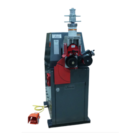
OPERATING AND MAINTENANCE INSTRUCTIONS MANUAL
VE414MC Roll Grooving Tool
• Wear safety glasses, hardhat, foot protection, and hearing protection while working around pipe
preparation tools.
• Save the operating and maintenance manual in a place accessible to all operators of the tool.
If you need additional copies of any literature, or if you have questions concerning the safe
and proper operation of any pipe preparation tools, contact Victaulic, P.O. Box 31, Easton, PA
18044-0031, Phone: 1-800-PICK VIC, E-Mail: pickvic@victaulic.com
TM-VE414MC REV_F
Failure to follow instructions and warnings could result in death or serious
personal injury, property damage, and product damage.
• Before operating or servicing any pipe preparation tools, read all
instructions in the operating and maintenance manual and all warning
labels on the tool.
Original Instructions
WARNING
TM-VE414MC
OGS
EndSeal
™
Advertisement
Table of Contents

Subscribe to Our Youtube Channel
Related Manuals for Victaulic EndSeal TM-VE414MC


Summary of Contents for Victaulic EndSeal TM-VE414MC
- Page 1 • Save the operating and maintenance manual in a place accessible to all operators of the tool. If you need additional copies of any literature, or if you have questions concerning the safe and proper operation of any pipe preparation tools, contact Victaulic, P.O. Box 31, Easton, PA 18044-0031, Phone: 1-800-PICK VIC, E-Mail: pickvic@victaulic.com...
-
Page 2: Table Of Contents
TM-VE414MC / Operating and Maintenance Instructions Manual TABLE OF CONTENTS Hazard Identification ....2 Maintenance ..... . 37 Operator Safety Instructions . -
Page 3: Hazard Identification
. Additional copies are available upon practices that could result in personal request through Victaulic, or can be downloaded injury and product or property damage at victaulic .com . if instructions, including recommended DANGER precautions, are not followed. - Page 4 . Do not overload the tool . moving parts . If the tool does not contain a Maintain tool with care. Keep the tool safety foot switch, contact Victaulic . clean at all times to ensure proper and Do not over-reach. Maintain proper footing safe performance .
-
Page 5: Introduction
The VE414MC Roll Grooving Tool is a motorized, semi-automatic, hydraulic-feed tool for roll Qty. Description grooving pipe to receive Victaulic grooved pipe VE414MC Pipe Roll Grooving Tool products . The VE414MC tool is supplied with matched rolls for grooving 2–12-inch/ Roll Set for 8–12-inch/219.1–323.9-mm... -
Page 6: Power Requirements
• HYDRAULIC OIL – HIGH-PRESSURE, ANTI-WEAR ISO GRADE 32 R-740-414-SCH • BEARING LUBE – ANTI-WEAR, EXTREME PRESSURE NLGI GRADE 2 REVISION LEVEL The VE414MC Roll Grooving Tool is designed Victaulic Company World Headquarters Manufactured in Canada 4901 Kesslersville Road • Easton, PA 18040 victaulic.com to operate on several different electrical 12934 Rev. -
Page 7: Tool Nomenclature
• Drawings and/or pictures in this manual may be exaggerated for clarity. • The tool, along with this operating and maintenance instructions manual, contains trademarks, copyrights, and/or patented features that are the exclusive property of Victaulic. Pipe Size Indicator Depth Adjuster Lock... -
Page 8: Tool Dimensions And Specifications
TM-VE414MC / Operating and Maintenance Instructions Manual TOOL DIMENSIONS AND SPECIFICATIONS 37.50 in/ 14.00 in/ 953 mm 356 mm 51.00 in/ 1295 mm 60.50 in/ 1537 mm 36.62 in/ 930 mm 22.25 in/ 27.00 in/ 565 mm 686 mm 24.00 in/ 30.00 in/ 610 mm 762 mm... -
Page 9: Tool Setup
TM-VE414MC / Operating and Maintenance Instructions Manual TOOL SETUP WARNING • DO NOT turn on the main power supply to the tool until instructed otherwise. • The tool SHALL be leveled and anchored securely on a concrete floor or base. Failure to follow these instructions could result in serious personal injury. - Page 10 TM-VE414MC / Operating and Maintenance Instructions Manual NOTICE • VE414MC tools are equipped with a detachable safety foot switch cord. The safety foot switch can be removed easily for storage in the cabinet when the tool is not in use. 5.
-
Page 11: Verification Of Pipe Rotation Direction
TM-VE414MC / Operating and Maintenance Instructions Manual VERIFICATION OF PIPE ROTATION DIRECTION The VE414MC tool is equipped with a “JOG” setting . Operating the tool in the “JOG” setting allows for: • Determining rotation of the tool’s lower roll • Confirming that the pipe to be grooved is tracking properly on the lower roll 4. - Page 12 (circuit breaker panel, knife switch, etc .) . 11. Follow steps 1 – 6 to check rotational direction of the lower roll . If rotational direction is not clockwise, contact Victaulic . If rotational direction is clockwise, the verification procedure is complete .
-
Page 13: Emergency Stop Operation
“EMERGENCY STOP” button is activated. • If the motor can be energized while the “EMERGENCY STOP” button is activated, discontinue use and contact Victaulic. Failure to follow this instruction could result in serious personal injury. 2. Press the “RESET” button . - Page 14 . discontinue use and contact Victaulic. Failure to follow this instruction could result in serious personal injury. 8b. Turn the selector switch to the “JOG”...
-
Page 15: Preparing Pipe For Grooving
. damage grooving rolls, resulting in distorted Table 1 identifies the minimum pipe lengths grooves or grooves that are out of Victaulic that can be grooved safely by using Victaulic specifications. -
Page 16: Checking And Adjusting The Tool Prior To Grooving
CHECKING AND ADJUSTING THE TABLE 1- PIPE LENGTHS SUITABLE FOR GROOVING TOOL PRIOR TO GROOVING Steel, Stainless Steel, Every Victaulic roll grooving tool is checked, Aluminum, and PVC adjusted, and tested at the factory prior to Pipe Size Length – inches/mm shipment . -
Page 17: Adjusting The Roll Guards
TM-VE414MC / Operating and Maintenance Instructions Manual ADJUSTING THE ROLL GUARDS CAUTION • The “Adjusting the Roll Guards” section shall be completed with every roll change. • Verify that the upper and lower grooving rolls are a matched set and are properly lubricated. - Page 18 TM-VE414MC / Operating and Maintenance Instructions Manual 6. Set the main power switch to the “ON” position . 5. Insert a length of pipe that is the correct size and thickness onto the lower roll . Ensure that the pipe end contacts the lower-roll backstop flange completely .
- Page 19 TM-VE414MC / Operating and Maintenance Instructions Manual CAUTION • Use the “JOG” setting only for pre- operation adjustments to the tool. When the tool is left in the “JOG” setting with the power on, the pipe will be gradually released. This may result in the pipe falling out of the tool.
- Page 20 TM-VE414MC / Operating and Maintenance Instructions Manual 3. Insert a length of pipe that is the correct size FIGURE 1 and thickness onto the lower roll . Ensure that the pipe end contacts the lower-roll backstop flange completely . Remove hands from the pipe . 1.
-
Page 21: Ram Speed Adjustment
TM-VE414MC / Operating and Maintenance Instructions Manual 8. Prepare to support the pipe, and turn the selector switch to the “NORMAL” position . The arm/upper roll assembly will return to its upper position, and the pipe will release . CAUTION •... - Page 22 TM-VE414MC / Operating and Maintenance Instructions Manual The ram speed adjustment is factory set for roll Ram Speed grooving steel pipe . If the pipe being grooved Pipe Control is another material, the ram speed must be Material Valve Setting * re-adjusted .
-
Page 23: Dwell Control Adjustment
TM-VE414MC / Operating and Maintenance Instructions Manual DWELL CONTROL ADJUSTMENT The dwell control adjustment controls the length of time the tool continues to rotate the pipe after the groove diameter stop contacts the top of the hydraulic cylinder . The dwell control timer is adjustable for time range and pipe size settings . -
Page 24: Pipe Size Adjustment
TM-VE414MC / Operating and Maintenance Instructions Manual PIPE SIZE ADJUSTMENT Indicator Rotate the timer dial to the appropriate pipe size . Barrel 3. Unlock the depth adjuster lock (clockwise) from the depth adjuster . Align the top edge of the depth adjuster with the lowest line position of the proper size and schedule markings on the indicator barrel . - Page 25 5. Prepare a trial groove . Refer to the “Grooving • The “C” dimension (groove diameter) Operation” section . shall conform to Victaulic specifications to ensure proper joint performance. Failure to follow this instruction could cause joint failure, resulting in property damage or personal injury.
-
Page 26: Grooving Short Pipe Lengths
TM-VE414MC / Operating and Maintenance Instructions Manual GROOVING SHORT PIPE 7. If the groove diameter (“C” dimension) is not within Victaulic specifications, the diameter stop LENGTHS shall be adjusted . DANGER a. Unlock the depth adjusters . b. To adjust for a smaller groove diameter •... - Page 27 TM-VE414MC / Operating and Maintenance Instructions Manual WARNING Grooving rolls can crush or cut fingers and hands. • Always turn off the main power supply to the tool before making any tool adjustments. • Loading/unloading pipe will place your 4. Ensure that the selector switch on the control hands close to the rollers.
- Page 28 Release the safety foot switch, and withdraw foot from the switch . 10. Inspect the groove/pipe end to ensure they are within Victaulic specifications . 11. If roll grooving will not be performed for an extended time period, turn off the hydraulic system by turning off the main power switch on the side of the tool .
-
Page 29: Grooving Long Pipe Lengths
TM-VE414MC / Operating and Maintenance Instructions Manual GROOVING LONG PIPE LENGTHS Tool DANGER Centerline (level) • To reduce the risk of electric shock, check the tool for proper Pipe grounding and follow all Centerline ½° to 1° instructions. 2 to 4 inches/ 50 to 100 mm •... - Page 30 TM-VE414MC / Operating and Maintenance Instructions Manual 5. Before grooving, ensure that all instructions in the previous sections of this manual have been followed . 6. Turn on the main power supply to the tool (circuit breaker panel, knife switch, etc .) . 10.
- Page 31 . Remove hands from the pipe . 12. The operator should be positioned as 16. Inspect the groove/pipe end to ensure they shown . are within Victaulic specifications . NOTICE • Occasionally during grooving, the groove diameter stop may move up and down...
-
Page 32: Roll Changing
TM-VE414MC / Operating and Maintenance Instructions Manual ROLL CHANGING 17. If roll grooving will not be performed for an extended time period, turn off the hydraulic VE414MC tools are designed with rolls to system by turning off the main power switch on accommodate several pipe sizes and materials, the side of the tool . - Page 33 TM-VE414MC / Operating and Maintenance Instructions Manual 3. Pull the “EMERGENCY STOP” button on the control panel to the out position . 6. Use the safety foot switch to energize the tool and to bring the upper roll down into firm contact with the pipe .
-
Page 34: Upper Roll Removal For 4 - 16"/114 .3 - 406 .4 Mm Sizes
TM-VE414MC / Operating and Maintenance Instructions Manual UPPER ROLL REMOVAL FOR 4 – 16”/114.3 – 406.4 MM SIZES 8. Verify that the guards are adjusted per the “Roll Guard Adjustment” section . 1. Set the main power switch to the “OFF” position . -
Page 35: Lower Roll Removal For 4 - 16"/114 .3 - 406 .4 Mm Sizes
TM-VE414MC / Operating and Maintenance Instructions Manual LOWER ROLL REMOVAL FOR UPPER AND LOWER ROLL INSTALLATION 4 – 16”/114.3 – 406.4 MM SIZES FOR 2 – 31/2”/60.3 – 101.6 MM SIZES 1. Lightly lubricate the lower shaft with a thin 1. Loosen and remove the lower roll’s bolt film of oil or grease before installing the lower and retaining plate, as shown . -
Page 36: Lower Roll Installation For 4 - 16"/114 .3 - 406 .4 Mm Sizes
TM-VE414MC / Operating and Maintenance Instructions Manual LOWER ROLL INSTALLATION FOR 4 – 16”/114.3 – 406.4 MM SIZES NOTICE • Clean the main shaft and the lower roll’s bore of any dirt and/or scale before installation. Make any repairs, as necessary. -
Page 37: Upper Roll Installation For 4 - 16"/114 .3 - 406 .4 Mm Sizes
TM-VE414MC / Operating and Maintenance Instructions Manual UPPER ROLL INSTALLATION FOR 4 – 16”/114.3 – 406.4 MM SIZES NOTICE • Clean the upper shaft of any dirt and/or scale before installing the upper roll. • Inspect the roller bearing, inside the upper roll, for proper lubrication and condition. -
Page 38: Maintenance
. Replacement parts shall be ordered from 1. Lubricate the slide gibs at the two grease Victaulic to ensure proper and safe operation of fittings, as shown . the tool . 2. Lubricate the upper roll bearing at the fitting, as shown . -
Page 39: Checking And Filling Gear Reducer Oil
TM-VE414MC / Operating and Maintenance Instructions Manual GEAR REDUCER INPUT SHAFT Grease Fitting Bleeder Fitting 4. Lubricate the stabilizer wheel, as shown . CHECKING AND FILLING GEAR REDUCER OIL 1. The gear reducer’s input shaft cover contains The gear reducer oil level shall be checked every a grease fitting (shown above) . -
Page 40: Replacing Hydraulic Oil And Filter
TM-VE414MC / Operating and Maintenance Instructions Manual REPLACING HYDRAULIC OIL AND FILTER NOTICE Replace the hydraulic oil and hydraulic oil • Reference local ordinances regarding the filter annually or every 2,000 operating hours, proper disposal of hydraulic oil. whichever comes first . 1. -
Page 41: Air Bleeding
TM-VE414MC / Operating and Maintenance Instructions Manual 9. Turn on the main power supply to the tool (circuit breaker panel, knife switch, etc .) . 14. Turn off the hydraulic system by pushing 10. Set the main power switch to the “ON” the “EMERGENCY STOP”... - Page 42 TM-VE414MC / Operating and Maintenance Instructions Manual 7. Set the main power switch to the “ON” position . 4. Remove the hydraulic breather cap/dipstick . 8. Turn the selector switch to the “JOG” position . 9a. Depress the safety foot switch . The fluid will start to flow through the bleeder tube (the fluid should contain air bubbles) .
-
Page 43: Recommended Lubricants
TM-VE414MC / Operating and Maintenance Instructions Manual 16. Set the main power switch to the “OFF” 12. Set the depth stop on the tool to obtain position . approximately a 1/4-inch/5-mm gap between the RECOMMENDED LUBRICANTS depth stop and the cylinder . BEARING AND SLIDE GREASE NLGI #2 Summer Grade graphite moly base (General Purpose EP Lithium Base Grease) -
Page 44: Accessories
VAPS112, but supports pipe sizes 2 to 24 inches/60 .3 to 610 .0 The Victaulic VAPS112 Pipe Stand is a portable, mm (11/2-foot/0 .5-meter to full, single 20-foot/6- adjustable, roller-type pipe stand that contains meter random lengths) and has a load rating of four legs for additional stability . -
Page 45: Troubleshooting
Dirt is trapped between the roll and slide or Remove the upper roll, and clean off any dirt. Re-install the upper roll. the retaining plate. In the event of tool malfunction outside the scope of the troubleshooting section, contact Victaulic for assis- tance. TM-VE414MC REV_F... -
Page 46: Ve414Mc Ratings - Maximum Pipe Size And Wall Thickness Capacity (Ogs)
• The “Maximum Pipe Size and Wall Thickness Capacity” tables below are accurate as of the date printed on the back cover of this manual. For the most up-to-date information, reference Victaulic publication 24.01, which can be viewed/downloaded by scanning the mobile QR code link to the right, or by clicking on this desktop link: https://www.victaulic.com/assets/uploads/literature/24.01.pdf... -
Page 47: Roll Part Numbers
ORIGINAL GROOVE SYSTEM (OGS) ORIGINAL GROOVE SYSTEM (OGS) ROLL PART NUMBERS ROLL PART NUMBERS STEEL AND SCHEDULE 40 STAINLESS STEEL ALUMINUM AND PVC PLASTIC PIPE - PIPE - COLOR CODED BLACK COLOR CODED YELLOW ZINC (For light-wall stainless steel pipe, refer to separate table Pipe Size Roll Part on this page) -
Page 48: Link To Ogs Groove Specifications
For the most up-to-date information regarding OGS roll groove specifications, reference the current revision of Victaulic publication 25 .01, which can be viewed/downloaded by scanning the mobile QR code link to the right, or by clicking on this desktop link: https://www . - Page 51 OPERATING AND MAINTENANCE INSTRUCTIONS MANUAL VE414MC Roll Grooving Tool TM-VE414MC 3303 REV F UPDATED 12/2022 RM00414000 VICTAULIC IS A REGISTERED TRADEMARK OF VICTAULIC COMPANY AND/OR ITS AFFILIATED ENTITIES IN THE UNITED STATES AND/OR OTHER COUNTRIES. © 2022 VICTAULIC COMPANY. ALL RIGHTS RESERVED.
Need help?
Do you have a question about the EndSeal TM-VE414MC and is the answer not in the manual?
Questions and answers