Table of Contents
Advertisement
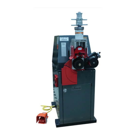
OPERATING AND MAINTENANCE INSTRUCTIONS MANUAL
VE414MC and VE415MC Roll Grooving Tools
WARNING
If you need additional copies of any literature, or if you have questions concerning the safe
and proper operation of this tool, contact Victaulic, P.O. Box 31, Easton, PA 18044-0031,
Phone: 1-800-PICK VIC, E-Mail: pickvic@victaulic.com.
REV_D
WARNING
Failure to follow instructions and warnings could result in death,
serious personal injury, property damage, and/or product damage.
• Before operating or servicing any roll grooving tools, read all
instructions in this manual and all warning labels on the tool.
• Wear safety glasses, hardhat, foot protection, and hearing
protection while working around this tool.
• Save this operating and maintenance manual in a place
accessible to all operators of the tool.
Original Instructions
TM-VE414/415MC
EndSeal
TM-VE414/415MC
OGS
™
Advertisement
Table of Contents

Related Manuals for Victaulic VE414MC


Summary of Contents for Victaulic VE414MC
- Page 1 If you need additional copies of any literature, or if you have questions concerning the safe and proper operation of this tool, contact Victaulic, P.O. Box 31, Easton, PA 18044-0031, Phone: 1-800-PICK VIC, E-Mail: pickvic@victaulic.com.
-
Page 3: Table Of Contents
TM-VE414/415MC / Operating and Maintenance Instructions Manual TABLE OF CONTENTS Maintenance ..... . 39 Lubrication ......39 Hazard Identification . -
Page 4: Hazard Identification
Additional copies • The use of the word “CAUTION” of this manual are available upon request identifies possible hazards or unsafe through Victaulic, or can be downloaded at practices that could result in personal victaulic.com. injury and product or property damage... - Page 5 Do not over-reach. Maintain proper footing for lubricating tool components. and balance at all times. Ensure that the 10. Use only Victaulic replacement parts safety foot switch is easily accessible to the and accessories. Use of any other parts operator.
-
Page 6: Introduction
The VE414/415MC Roll Grooving Tool is a motorized, semi-automatic, hydraulic-feed Qty. Description tool for roll grooving pipe to receive Victaulic grooved pipe products. The VE414/415MC tool VE414MC Pipe Roll Grooving Tool is supplied with matched rolls for grooving Roll Set for 8–12-inch/219.1–323.9-mm 2–12-inch/60.3 –... -
Page 7: Power Requirements
Refer to the electrical schematic in the RP-VE414/415MC Repair Parts List and the The VE414MC tool is supplied with a #10/4 line information contained on the nameplate on the cord (3 power, 1 ground) and is set up for 230- tool’s drive motor and hydraulic pump motor. -
Page 8: Tool Nomenclature
TOOL NOMENCLATURE NOTICE • Drawings and/or pictures in this manual may be exaggerated for clarity. • The tool, along with this operating and maintenance instructions manual, contains trademarks, copyrights, and/or patented features that are the exclusive property of Victaulic. REV_D TM-VE414/415MC_8... -
Page 9: Tool Dimensions And Specifications
TM-VE414/415MC / Operating and Maintenance Instructions Manual TOOL DIMENSIONS AND SPECIFICATIONS 37.50 in/ 14.00 in/ 953 mm 356 mm 51.00 in/ 1295 mm 60.50 in/ 1537 mm 36.62 in/ 930 mm 22.25 in/ 27.00 in/ 565 mm 686 mm 24.00 in/ 30.00 in/ 610 mm 762 mm... -
Page 10: Tool Setup
TM-VE414/415MC / Operating and Maintenance Instructions Manual TOOL SETUP WARNING • DO NOT turn on the main power supply to the tool until instructed otherwise. • The tool SHALL be leveled and anchored securely on a concrete floor or base. Failure to follow these instructions could result in serious personal injury. - Page 11 TM-VE414/415MC / Operating and Maintenance Instructions Manual NOTICE • VE414/415MC tools are equipped with a detachable safety foot switch cord. The safety foot switch can be removed easily for storage in the cabinet when the tool is not in use. 5.
-
Page 12: Verification Of Pipe Rotation Direction
TM-VE414/415MC / Operating and Maintenance Instructions Manual VERIFICATION OF PIPE ROTATION DIRECTION The VE414/415MC tool is equipped with a “JOG” setting. Operating the tool in the “JOG” setting allows for: • Determining rotation of the tool’s lower roll • Confirming that the pipe to be grooved is tracking properly on the lower roll 3. - Page 13 6. Proper rotation of the lower roll is clockwise 8a. Secure a lockout mechanism to the tool. when viewed from the front of the tool. If NOTE: Victaulic does not supply this lockout rotation is clockwise, power hookup is complete. mechanism.
-
Page 14: Emergency Stop Operation
“EMERGENCY STOP” button is activated. • If the motor can be energized while the “EMERGENCY STOP” button is activated, discontinue use and contact Victaulic. Failure to follow this instruction could result in serious personal injury. 2. Press the “RESET” button. - Page 15 Victaulic. Failure to follow this instruction could result in serious personal injury. 8b. Turn the selector switch to the “JOG”...
-
Page 16: Preparing Pipe For Grooving
Rust is an abrasive material that PIPE LENGTH REQUIREMENTS will wear the surface of grooving rolls. VE414MC tools are capable of grooving short Foreign material may interfere with or pipe lengths without the use of a pipe stand. damage grooving rolls, resulting in distorted... -
Page 17: Checking And Adjusting The Tool Prior To Grooving
CHECKING AND ADJUSTING THE TABLE 1- PIPE LENGTHS SUITABLE FOR GROOVING TOOL PRIOR TO GROOVING Every Victaulic roll grooving tool is checked, Steel, Stainless Steel, Aluminum, and PVC Pipe Size Length – inches/mm adjusted, and tested at the factory prior to shipment. -
Page 18: Adjusting The Roll Guards
NOTE: Both the VE414 and the VE414MC use the same upper and lower grooving roll sets, as well as other features. Because of similarities... - Page 19 TM-VE414/415MC / Operating and Maintenance Instructions Manual 6. Set the main power switch to the “ON” position. 5. Insert a length of pipe that is the correct size and thickness onto the lower roll. Ensure that the pipe end contacts the lower-roll backstop flange completely.
-
Page 20: Pipe Stabilizer Adjustment
TM-VE414/415MC / Operating and Maintenance Instructions Manual CAUTION • Use the “JOG” setting only for pre- operation adjustments to the tool. When the tool is left in the “JOG” setting with the power on, the pipe will be gradually released. This may result in the pipe falling out of the tool. - Page 21 TM-VE414/415MC / Operating and Maintenance Instructions Manual 3. Insert a length of pipe that is the correct size FIGURE 1 and thickness onto the lower roll. Ensure that the pipe end contacts the lower-roll backstop flange completely. Remove hands from the pipe. 1.
-
Page 22: Ram Speed Adjustment
• DO NOT adjust the pipe stabilizer while ram speed may need to be re-adjusted. the pipe is in motion. NOTE: Both the VE414 and the VE414MC use • Assembly of couplings on pipe that the same upper and lower grooving roll sets, as exceeds the maximum allowable flare well as other features. - Page 23 TM-VE414/415MC / Operating and Maintenance Instructions Manual The ram speed adjustment is factory set for roll Ram Speed grooving steel pipe. If the pipe being grooved Pipe Control is another material, the ram speed must be Material Valve Setting * re-adjusted.
-
Page 24: Dwell Control Adjustment
TM-VE414/415MC / Operating and Maintenance Instructions Manual DWELL CONTROL ADJUSTMENT The dwell control adjustment controls the length of time the tool continues to rotate the pipe after the groove diameter stop contacts the top of the hydraulic cylinder. The dwell control timer is adjustable for time range and pipe size settings. -
Page 25: Pipe Size Adjustment
TM-VE414/415MC / Operating and Maintenance Instructions Manual PIPE SIZE ADJUSTMENT Rotate the timer dial to the appropriate pipe size. 3. Unlock the groove diameter stop (clockwise) from the depth adjuster. Align the top edge of the depth adjuster with the lowest line position of the proper size and schedule markings on the indicator barrel. - Page 26 5. Prepare a trial groove. Refer to the “Grooving Operation” section. • The “C” dimension (groove diameter) shall conform to Victaulic specifications to ensure proper joint performance. Failure to follow this instruction could cause joint failure, resulting in property damage or personal injury.
-
Page 27: Grooving Short Pipe Lengths
TM-VE414/415MC / Operating and Maintenance Instructions Manual GROOVING SHORT PIPE 7. If the groove diameter (“C” dimension) is not within Victaulic specifications, the diameter stop LENGTHS shall be adjusted. DANGER a. Unlock the depth adjusters. b. To adjust for a smaller groove diameter •... - Page 28 TM-VE414/415MC / Operating and Maintenance Instructions Manual WARNING Grooving rolls can crush or cut fingers and hands. • Always turn off the main power supply to the tool before making any tool adjustments. • Loading/unloading pipe will place your 4. Ensure that the selector switch on the control hands close to the rollers.
- Page 29 Release the safety foot switch, and withdraw foot from the switch. 10. Inspect the groove/pipe end to ensure they are within Victaulic specifications. 11. If roll grooving will not be performed for an extended time period, turn off the hydraulic system by pushing the “EMERGENCY STOP”...
-
Page 30: Grooving Long Pipe Lengths
TM-VE414/415MC / Operating and Maintenance Instructions Manual GROOVING LONG PIPE LENGTHS Tool Centerline (Level) DANGER Pipe angle ½° to 1° exaggerated for clarity (2 to 4") • To reduce the risk of electric shock, check the tool for proper Pipe grounding and follow all Centerline instructions. - Page 31 TM-VE414/415MC / Operating and Maintenance Instructions Manual 5. Before grooving, ensure that all instructions in the previous sections of this manual have been followed. 6. Turn on the main power supply to the tool (circuit breaker panel, knife switch, etc.). 10.
- Page 32 Remove hands from the pipe. 16. Inspect the groove/pipe end to ensure they 12. The operator should be positioned as are within Victaulic specifications. shown. NOTICE • Occasionally during grooving, the groove diameter stop may move up and down...
-
Page 33: Roll Changing
TM-VE414/415MC / Operating and Maintenance Instructions Manual ROLL CHANGING 17. If roll grooving will not be performed for an extended time period, turn off the hydraulic VE414/415MC tools are designed with rolls to system by pushing the “EMERGENCY STOP” accommodate several pipe sizes and materials, button on the control panel. - Page 34 TM-VE414/415MC / Operating and Maintenance Instructions Manual 3. Pull the “EMERGENCY STOP” button on the control panel to the out position. 6. Use the safety foot switch to energize the tool and to bring the upper roll down into firm contact with the pipe.
-
Page 35: Upper Roll Removal For 4 - 16"/114.3 - 406.4 Mm Sizes
TM-VE414/415MC / Operating and Maintenance Instructions Manual UPPER ROLL REMOVAL FOR 4 – 16"/114.3 – 406.4 MM SIZES 8. Verify that the guards are adjusted per the “Roll Guard Adjustment” section. 1. Set the main power switch to the “OFF” position. -
Page 36: Lower Roll Removal For 4 - 16"/114.3 - 406.4 Mm Sizes
TM-VE414/415MC / Operating and Maintenance Instructions Manual LOWER ROLL REMOVAL FOR UPPER AND LOWER ROLL INSTALLATION 4 – 16”/114.3 – 406.4 MM SIZES FOR 2 – 31/2"/60.3 – 101.6 MM SIZES 1. Lightly lubricate the lower shaft with a thin 1. Loosen and remove the lower roll’s bolt film of oil or grease before installing the lower and retaining plate, as shown. -
Page 37: Lower Roll Installation For 4 - 16"/114.3 - 406.4 Mm Sizes
TM-VE414/415MC / Operating and Maintenance Instructions Manual LOWER ROLL INSTALLATION FOR 4 – 16"/114.3 – 406.4 MM SIZES NOTICE • Clean the main shaft and the lower roll’s bore of any dirt and/or scale before installation. Make any repairs, as necessary. -
Page 38: Upper Roll Installation For 4 - 16"/114.3 - 406.4 Mm Sizes
TM-VE414/415MC / Operating and Maintenance Instructions Manual UPPER ROLL INSTALLATION FOR 4 – 16"/114.3 – 406.4 MM SIZES NOTICE • Clean the upper shaft of any dirt and/or scale before installing the upper roll. • Inspect the roller bearing, inside the upper roll, for proper lubrication and condition. -
Page 39: Maintenance
1. Lubricate the slide gibs at the two grease pay for itself in repair and operating savings. fittings, as shown. Replacement parts shall be ordered from Victaulic to ensure proper and safe operation of the tool. 2. Lubricate the upper roll bearing at the fitting, as shown. -
Page 40: Checking And Filling Gear Reducer Oil
TM-VE414/415MC / Operating and Maintenance Instructions Manual GEAR REDUCER INPUT SHAFT Grease Fitting Bleeder Fitting 4. Lubricate the stabilizer wheel, as shown. 1. The gear reducer’s input shaft cover contains CHECKING AND FILLING GEAR a grease fitting (shown above). This grease REDUCER OIL fitting is located on the chain coupling side of The gear reducer oil level shall be checked... -
Page 41: Replacing Hydraulic Oil And Filter
TM-VE414/415MC / Operating and Maintenance Instructions Manual REPLACING HYDRAULIC OIL AND NOTICE FILTER • Reference local ordinances regarding the Replace the hydraulic oil and hydraulic oil filter proper disposal of hydraulic oil. annually or every 2,000 hours of operation, whichever comes first. 1. -
Page 42: Air Bleeding
TM-VE414/415MC / Operating and Maintenance Instructions Manual 9. Turn on the main power supply to the tool (circuit breaker panel, knife switch, etc.). 14. Turn off the hydraulic system by pushing 10. Set the main power switch to the “ON” the “EMERGENCY STOP”... - Page 43 TM-VE414/415MC / Operating and Maintenance Instructions Manual 7. Set the main power switch to the “ON” position. 4. Remove the hydraulic breather cap/dipstick. 8. Turn the selector switch to the “JOG” position. 9a. Depress the safety foot switch. The fluid will start to flow through the bleeder tube (the fluid should contain air bubbles).
-
Page 44: Recommended Lubricants
TM-VE414/415MC / Operating and Maintenance Instructions Manual 16. Set the main power switch to the “OFF” 12. Set the depth stop on the tool to obtain position. approximately a 1/4-inch/5-mm gap between the RECOMMENDED LUBRICANTS depth stop and the cylinder. BEARING AND SLIDE GREASE NLGI #2 Summer Grade graphite moly base (General Purpose EP Lithium Base Grease) -
Page 45: Accessories
PARTS ORDERING INFORMATION VAPS 112 VICTAULIC ADJUSTABLE PIPE STAND When ordering parts, the following information is required for Victaulic to process the order and send the correct part(s). Parts can be ordered by calling 1-800-PICK-VIC. Tool Model Number Tool Serial Number... -
Page 46: Troubleshooting
Dirt is trapped between the roll and slide or Remove the upper roll, and clean off any dirt. Re-install the upper the retaining plate. roll. In the event of tool malfunction outside the scope of the troubleshooting section, contact Victaulic for assistance. REV_D TM-VE414/415MC_46... - Page 47 This page intentionally blank...
-
Page 48: Tool Rating And Roll Selection
The wall thicknesses listed are nominal minimum and maximum In addition, the following pipe sizes may be roll grooved: 76.1 mm; 108.0 mm; 127.0 mm; 133.0 mm; 139.7 mm; 159.0 mm; 165.1 mm; 216.3 mm; 267.4 mm; and 318.5 mm. Contact Victaulic for details. REV_D... - Page 49 Column 2: PVC Type 1. Grade 1 – PVC 1120; PVC Type 1. Grade II – PVC 1220; PVC Type II. Grade I – PVC 2116 The wall thicknesses listed are nominal minimum and maximum In addition. the following pipe sizes may be roll grooved: 76.1 mm; 108.0 mm; 133.0 mm; 139.7 mm; 159.0 mm; and 165.1 mm. Contact Victaulic for details. REV_D TM-VE414/415MC_49...
- Page 50 The wall thicknesses listed are nominal minimum and maximum In addition, the following pipe sizes may be roll grooved: 76.1 mm; 108.0 mm; 133.0 mm; 139.7 mm; 152.4 mm; 159.0 mm; 165.1 mm; and 203.2 mm. Contact Victaulic for details. REV_D...
- Page 51 TM-VE414/415MC / Operating and Maintenance Instructions Manual ROLLS FOR CTS US STANDARD – ASTM DRAWN COPPER TUBING – COLOR-CODED COPPER Nominal Wall Thickness Dimensions – inches/millimeter * Actual Outside Copper Tubing Wall Thickness ‡ Nominal Size Diameter Copper Roll inches/mm inches/mm Min.
- Page 52 TM-VE414/415MC / Operating and Maintenance Instructions Manual ROLLS FOR EUROPEAN STANDARD – EN 1057 DRAWN COPPER TUBING – COLOR-CODED COPPER Dimensions – millimeters/inches Copper Tubing Wall Thickness ‡ Nominal Size Copper Roll Minimum Maximum Part Numbers 54.0 0.047 0.079 64.0 0.079 0.079 66.7...
- Page 53 TM-VE414/415MC / Operating and Maintenance Instructions Manual ROLLS FOR AUSTRALIAN STANDARD – AS 1432 DRAWN COPPER TUBING – COLOR CODED COPPER Dimensions – millimeters/inches Copper Tubing Wall Thickness ‡ Nominal Size Copper Roll Minimum Maximum Part Numbers DN 50 0.035 0.063 DN 65 0.035...
-
Page 54: Explanation Of Critical Roll Groove Dimensions
NOTICE FOR OGS COUPLINGS WITH RATINGS ON LIGHT-WALL STAINLESS STEEL PIPE: • Victaulic RX rolls SHALL be used when roll grooving light-wall stainless steel pipe for use with OGS couplings. Pipe Outside Diameter – Nominal NPS Pipe Size (ANSI B36.10) and Basic Metric Pipe Size (ISO 4200) –... - Page 55 “T” Dimension – The “T” dimension is the lightest grade (minimum nominal wall thickness) of pipe that is suitable for cut or roll grooving. Pipe that is less than the minimum nominal wall thickness for cut grooving may be suitable for roll grooving or adapted for Victaulic couplings by using Vic-Ring ®...
- Page 56 TM-VE414/415MC / Operating and Maintenance Instructions Manual EXPLANATION OF CRITICAL ROLL GROOVE DIMENSIONS FOR ADVANCED GROOVE SYSTEM (AGS) PRODUCTS WARNING • Pipe dimensions and groove dimensions shall be within the tolerances specified in the tables on the following pages to ensure proper joint performance. Failure to follow these specifications could cause joint failure, resulting in serious personal injury and/or property damage.
- Page 57 OD for proper coupling fit. The groove shall be of uniform depth for the entire pipe circumference. Victaulic RW roll sets shall be used for carbon steel and standard-wall stainless steel pipe. Victaulic RWX roll sets shall be used for light-wall stainless steel pipe.
- Page 58 20–22-inch/508–559-mm minimum nominal wall thickness is 0.188 inch/4.8 mm 24-inch/610-mm minimum nominal wall thickness is 0.218 inch/5.5 mm NOTICE • Coatings that are applied to the interior surfaces of Victaulic grooved and plain-end pipe couplings shall not exceed 0.010 inch/0.25 mm. This includes the bolt pad mating surfaces.
- Page 59 This page intentionally blank...
-
Page 60: Roll Groove Specifications
TM-VE414/415MC / Operating and Maintenance Instructions Manual REV_D TM-VE414/415MC_60... - Page 61 TM-VE414/415MC / Operating and Maintenance Instructions Manual REV_D TM-VE414/415MC_61...
- Page 62 TM-VE414/415MC / Operating and Maintenance Instructions Manual REV_D TM-VE414/415MC_62...
-
Page 63: Ec Declaration Of Conformity
Director – Global Regulatory Compliance Machinery Manufacturer Representative Place of Issue: Easton, Pennsylvania, USA Date of Issue: May 1, 2020 MD_DoC_RGT_011_050120_en.docx Victaulic and all other Victaulic marks and logos are registered trademarks of Victaulic Company and/or its affiliates. ©2020 All Rights Reserved... - Page 64 OPERATING AND MAINTENANCE INSTRUCTIONS MANUAL VE414MC and VE415MC Roll Grooving Tools UPDATED 08/2020 TM-VE414/415MC 3303 REV D RM00414000 VICTAULIC IS A REGISTERED TRADEMARK OF VICTAULIC COMPANY AND/OR ITS AFFILIATED ENTITIES IN THE UNITED STATES AND/OR OTHER COUNTRIES. © 2020 VICTAULIC COMPANY. ALL RIGHTS RESERVED.
Need help?
Do you have a question about the VE414MC and is the answer not in the manual?
Questions and answers