Victaulic VE272SFS Operating And Maintenance Instruction Manual
Pipe/tubing roll grooving tool
Hide thumbs
Also See for VE272SFS:
- Operating and maintenance instruction manual (52 pages) ,
- Operating and maintenance instruction manual (55 pages)
Table of Contents
Advertisement
Quick Links
BRAND
GROOVER MODEL
VICTAULIC
VE272SFS
VICTAULIC
VE270SFD
VICTAULIC
VE416FS
VICTAULIC
RG3212
VICTAULIC
VE460
RIGID
MODEL # 918
ROLLER PART NUMBER
RP08272012
RP08272012
RP08416012
RP08321212
RPQ1460012
NOTES
Parker approved and tested
Parker approves and tested
Not tested
Not tested
Not tested
WILL NOT WORK DO NOT USE
Advertisement
Chapters
Table of Contents
Troubleshooting

Subscribe to Our Youtube Channel
Related Manuals for Victaulic VE272SFS


Summary of Contents for Victaulic VE272SFS
- Page 1 BRAND GROOVER MODEL ROLLER PART NUMBER NOTES VICTAULIC VE272SFS RP08272012 Parker approved and tested VICTAULIC VE270SFD RP08272012 Parker approves and tested VICTAULIC VE416FS RP08416012 Not tested VICTAULIC RG3212 RP08321212 Not tested VICTAULIC VE460 RPQ1460012 Not tested RIGID MODEL # 918...
- Page 2 Failure to follow instructions and warnings could result in death or serious personal injury and property damage. • Before operating or servicing the VE272SFS tool read all instructions in this manual and all warning labels on the tool. • Wear safety glasses, hardhat, foot protection, and hearing protection.
-
Page 4: Table Of Contents
TM-VE272SFS / Operating and Maintenance Instructions Manual TABLE OF CONTENTS Maintenance ..... . 34 Hazard Identification ....4 Lubrication . -
Page 5: Hazard Identification
INSTRUCTIONS Definitions for identifying the various hazard levels are provided below . The VE272SFS is designed for the sole purpose of roll grooving pipe . These instructions must This safety alert symbol indicates be read and understood by each operator important safety messages . - Page 6 TM-VE272SFS / Operating and Maintenance Instructions Manual Disconnect the power cord from the CAUTION electrical source before servicing the tool. Only authorized personnel should This tool is designed ONLY for roll perform maintenance on the tool . Always grooving pipe/tubing sizes, materials, and disconnect the power cord from the wall thicknesses listed in the “Tool Rating...
-
Page 7: Introduction
TM-VE272SFS / Operating and Maintenance Instructions Manual INTRODUCTION CONTAINER CONTENTS NOTICE • Drawings and/or pictures in this manual may be exaggerated for clarity. • The tool, along with this operating and maintenance instructions manual, contains trademarks, copyrights, and/or patented features that are the exclusive property of Victaulic. -
Page 8: Power Requirements
TM-VE272SFS / Operating and Maintenance Instructions Manual POWER REQUIREMENTS EXTENSION CORD REQUIREMENTS When pre-wired outlets are not available and DANGER an extension cord must be used, it is important to use the proper cord size (i .e . Conductor Size •... -
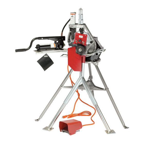
Page 9: Tool Nomenclature
If you need additional copies of any literature, or if you have questions concerning the safe and proper operation of any pipe preparation tools, contact Victaulic, P.O. Box 31, Easton, PA 18044-0031, Phone moving parts. -
Page 10: Tool Dimensions And Specifications
TM-VE272SFS / Operating and Maintenance Instructions Manual TOOL DIMENSIONS AND SPECIFICATIONS 15.00 in/ 381 mm 28.00 in/ 711 mm 56.25 in/ 1429 mm 37.00 in/ 940 mm 34.25 in/ 870 mm 27.50 in/ 699 mm 61.00 in/ 1549 mm Tool weight is 184 pounds/84 kilograms . -
Page 11: Tool Setup
Accidental startup of the tool could result in serious personal injury. The standard VE272SFS tool is intended for field Remove threading dies, cutoff or shop setup . Before grooving, the tool head attachments, etc . from the power drive . - Page 12 TM-VE272SFS / Operating and Maintenance Instructions Manual Allow approximately 1/2-inch/13-mm clearance from the hex bolts on the back of the tool to the power drive chuck . 10. Insert the top of the leg assembly Align the flat portions of the drive shaft...
- Page 13 TM-VE272SFS / Operating and Maintenance Instructions Manual 15. Attach the hand pump/pump support to 12. Loosen the hex bolts to release the two the left side of the tool with the two hex lower legs, allowing them to slide down to bolts (supplied) .
- Page 14 TM-VE272SFS / Operating and Maintenance Instructions Manual DANGER • To reduce the risk of electric shock, check the electrical source for proper grounding. • Before performing any maintenance on the tool, disconnect the power cord from the electrical source. 19. Turn the power drive switch to the position...
-
Page 15: Pre-Operation Checks And Adjustments
TM-VE272SFS / Operating and Maintenance Instructions Manual PRE-OPERATION CHECKS AND ADJUSTMENTS Every Victaulic roll grooving tool is checked, adjusted, and tested at the factory prior to shipment . However, before attempting to operate the tool, the following checks and adjustments should be made to ensure proper tool operation . -
Page 16: Pipe Preparation
TM-VE272SFS / Operating and Maintenance Instructions Manual GROOVABLE PIPE LENGTHS PIPE PREPARATION The VE272SFS is capable of grooving short pipe For proper tool operation and production of lengths without the use of a pipe stand . Refer to grooves that are within Victaulic specifications, the “Short Pipe Lengths”... - Page 17 TM-VE272SFS / Operating and Maintenance Instructions Manual TABLE 1 – PIPE LENGTHS SUITABLE FOR GROOVING CTS US Nominal Size Millimeters Length - millimeters Standard ASTM European Australian Steel, B-88 Standard Standard Stainless Steel, Copper Copper Copper Aluminum, Tubing Length –...
-
Page 18: Long Pipe Lengths
TM-VE272SFS / Operating and Maintenance Instructions Manual LONG PIPE LENGTHS Tool Centerline ½ to 1° When roll grooving pipe that exceeds the (Level) (2-4 inches/ 51-102 mm) maximum length shown in Table 1, a roller-type pipe stand must be used . The roller-type pipe stand must be capable of handling the weight of the pipe, while allowing the pipe to rotate freely . -
Page 19: Roll Guard Adjustment
TM-VE272SFS / Operating and Maintenance Instructions Manual ROLL GUARD ADJUSTMENT WARNING • Before making any tool adjustments, always disconnect the power cord from the electrical source. Accidental startup of the tool could result in serious personal injury. VE272SFS guards must be adjusted every time... - Page 20 TM-VE272SFS / Operating and Maintenance Instructions Manual WARNING Grooving rolls can crush or cut fingers and hands. • Before making any tool adjustments, always disconnect the power cord from the electrical source. • Loading and unloading pipe will place your hands close to the rollers. Keep...
-
Page 21: Pipe Stablizer Adjustment
PIPE STABLIZER ADJUSTMENT (Applies only to tools equipped with the optional pipe stabilizer) The optional pipe stabilizer for the VE272SFS is designed to prevent pipe sway for 8 – 12-inch/ 200 – 300 mm NPS sizes in short and long lengths . - Page 22 TM-VE272SFS / Operating and Maintenance Instructions Manual CAUTION • DO NOT adjust the stabilizer to push the pipe to the left and off center from the rolls. Increased pipe-end flare and shortened roll life will result if the pipe is pushed to the left and off center.
-
Page 23: Groove Diameter Stop Adjustment
TM-VE272SFS / Operating and Maintenance Instructions Manual GROOVE DIAMETER STOP ADJUSTMENT The groove diameter stop must be adjusted for each pipe size or change in wall thickness . The groove diameter, which is identified as the “C” dimension,” is listed under the “Roll Groove Specifications”... - Page 24 TM-VE272SFS / Operating and Maintenance Instructions Manual WARNING Grooving rolls can crush or cut fingers and hands. • Before making any tool adjustments, always disconnect the power cord from the electrical source. • Loading and unloading pipe will place your hands close to the rollers. Keep hands away from the grooving rolls during Back off the depth adjuster lock .
-
Page 25: Grooving Operation
TM-VE272SFS / Operating and Maintenance Instructions Manual GROOVING OPERATION CAUTION DANGER • The “C” dimension (groove diameter) and maximum allowable flare must conform to • To reduce the risk of Victaulic specifications to ensure proper electric shock, check joint performance. - Page 26 TM-VE272SFS / Operating and Maintenance Instructions Manual WARNING Grooving rolls can crush or cut fingers and hands. • Before making any tool adjustments, always disconnect the power cord from the electrical source. • Loading and unloading pipe will place Set the power drive switch to produce your hands close to the rollers.
- Page 27 TM-VE272SFS / Operating and Maintenance Instructions Manual NOTICE • DO NOT pump the handle too fast. The rate should be sufficient to groove the pipe and maintain an audible, moderate- to-heavy load on the power drive motor. Close the hand pump valve by turning the knob clockwise .
-
Page 28: Roll Changing
TM-VE272SFS / Operating and Maintenance Instructions Manual “Upper Roll Removal” section “Lower Roll Removal for 2-inch/50 mm and Larger Sizes” section “Lower Roll Installation for 2-inch/50 mm and Larger Sizes” section “Upper Roll Installation” section When 11/2-inch/40 mm and smaller size steel... - Page 29 TM-VE272SFS / Operating and Maintenance Instructions Manual LOWER ROLL REMOVAL FOR 2-INCH/ WARNING 50 MM AND LARGER SIZES • DO NOT strike the lower roll/ main shaft with a hammer or other blunt object. Striking the lower roll/main shaft can cause fragmentation, resulting in serious personal injury.
-
Page 30: Upper Roll Removal
TM-VE272SFS / Operating and Maintenance Instructions Manual UPPER ROLL REMOVAL With a wrench engaged on the exposed hex-portion stud of the arbor, loosen the arbor by turning counterclockwise. Using a wrench, loosen (counterclockwise) NOTE: The arbor should move outward as and remove the bolt from the upper roll . -
Page 31: Lower Roll/Adapter Assembly Installation
TM-VE272SFS / Operating and Maintenance Instructions Manual CAUTION NOTICE • NEVER operate the tool with jack bolts • The 3/4-inch/20 mm and 1 – 11/2-inch/ installed in the arbor. 25 – 40 mm lower roll/adapter assembly is held in position with left-hand threads... -
Page 32: Upper Roll Installation
TM-VE272SFS / Operating and Maintenance Instructions Manual UPPER ROLL INSTALLATION Refer to the “Tool Rating and Roll Selection” section for information regarding grooving rolls . Carefully slide the desired upper roll assembly onto the upper shaft with the red plate facing out . Loosen the guards, if necessary, to ease installation . -
Page 33: Lower Roll/Adapter Assembly Removal
TM-VE272SFS / Operating and Maintenance Instructions Manual LOWER ROLL/ADAPTER ASSEMBLY ARBOR INSTALLATION REMOVAL FOR 3/4-INCH/20 MM AND 1 – 11/2-INCH/25 – 40 MM SIZES Using a soft cloth, clean the bore of the main shaft and the arbor . Open the hand pump valve by turning the knob counterclockwise . -
Page 34: Lower Roll Installation For 2-Inch/50 Mm And Larger Sizes
TM-VE272SFS / Operating and Maintenance Instructions Manual 4a. Install the lower roll for the correct size and pipe material by referring to the “Lower Roll Installation” section . 4b. Make sure the upper roll is installed for the correct pipe size and material . -
Page 35: Maintenance
TM-VE272SFS / Operating and Maintenance Instructions Manual MAINTENANCE DANGER • Before performing any maintenance on the tool, disconnect the power cord from the electrical source. Failure to follow this instruction could result in Pump the hand pump several times until death or serious personal the upper roll interlocks with the lower roll . - Page 36 TM-VE272SFS / Operating and Maintenance Instructions Manual After every forty hours of operation, clean and lubricate the 3/4-inch/20 mm lower roll (if equipped) and the 1 – 11/2-inch/25 – 40 Grease the main shaft bearings at the mm lower roll .
-
Page 37: Checking And Filling Hydraulic Systems
TM-VE272SFS / Operating and Maintenance Instructions Manual CHECKING AND FILLING HYDRAULIC SYSTEMS The hydraulic fluid level in the hand pump must be checked semi-annually or if the pump feels “spongy . ” Open the hand pump valve by turning the knob counterclockwise . -
Page 38: Air Bleeding
15 to accommodate linear and rotational movement . 17 of the “Tool Setup” section . The turnstile design permits ease of grooving for both pipe ends . Contact Victaulic for details . REV_C TM-VE272SFS_37... - Page 39 TM-VE272SFS / Operating and Maintenance Instructions Manual VAPS 224 VICTAULIC ADJUSTABLE PIPE STABILIZER ASSEMBLY STAND The Victaulic VAPS 224 contains features that are similar to the VAPS 112, but it is suitable for A pipe stabilizer is available to prevent pipe 2 –...
- Page 40 TM-VE272SFS / Operating and Maintenance Instructions Manual This page intentionally blank REV_C TM-VE272SFS_39...
-
Page 41: Troubleshooting
TM-VE272SFS / Operating and Maintenance Instructions Manual TROUBLESHOOTING PROBLEM POSSIBLE CAUSE SOLUTION Pipe will not stay in grooving Incorrect pipe positioning of long pipe Refer to the "Long Pipe Lengths" section. rolls. length. Lower roll and pipe are not rotating Flip the switch on the power drive to the opposite rotation position. - Page 42 Incorrect upper roll, lower roll, or both Install the correct rolls. Refer to the "Tool Rating and Roll Selection" tions. installed on the tool. section. In the event of tool malfunction outside the scope of the troubleshooting section, contact Victaulic Engineering Services for assistance. REV_C TM-VE272SFS_41...
-
Page 43: Tool Rating And Roll Selection
* Types 304/304L and 316/316L stainless steel pipe In addition, the following pipe sizes may be roll grooved: 76.1 mm; 108.0 mm; 127.0 mm; 133.0 mm; 139.7 mm; 159.0 mm; 165.1 mm; 216.3 mm; 267.4 mm; and 318.5 mm. Contact Victaulic for details. REV_C... -
Page 44: Plastic Pipe
TM-VE272SFS / Operating and Maintenance Instructions Manual ORIGINAL GROOVE SYSTEM ROLLS FOR ALUMINUM AND PVC PLASTIC PIPE – COLOR-CODED YELLOW ZINC Pipe Size Dimensions - inches/millimeters Aluminum Pipe PVC Plastic Pipe Nominal Actual Wall Thickness † Wall Thickness * Size... -
Page 45: Rx Rolls For Schedule 5S And 10S Stainless Steel Pipe
The wall thicknesses listed are nominal minimum and maximum In addition, the following pipe sizes may be roll grooved: 76.1 mm; 108.0 mm; 133.0 mm; 139.7 mm; 152.4 mm; 159.0 mm; 165.1 mm; and 203.2 mm. Contact Victaulic for details. REV_C... -
Page 46: Rolls For Cts Us Standard
TM-VE272SFS / Operating and Maintenance Instructions Manual ROLLS FOR CTS US STANDARD – ASTM DRAWN COPPER TUBING – COLOR-CODED COPPER Pipe Size Dimensions – inches/millimeter Actual Copper Tubing Wall Thickness † Outside Copper Nominal Size Diameter Roll Part inches inches/mm... -
Page 47: Rolls For European Standard - En 1057 Drawn Copper Tubing
TM-VE272SFS / Operating and Maintenance Instructions Manual ROLLS FOR EUROPEAN STANDARD – EN 1057 DRAWN COPPER TUBING – COLOR-CODED COPPER Dimensions – millimeters/inches Copper Tubing Wall Thickness † Nominal Copper Size Roll Part Minimum Maximum Numbers 54.0 0.047 0.079 64.0 0.079... -
Page 48: Rolls For Australian Standard
TM-VE272SFS / Operating and Maintenance Instructions Manual ROLLS FOR AUSTRALIAN STANDARD – AS 1432 DRAWN COPPER TUBING – COLOR CODED COPPER Dimensions – millimeters/inches Copper Tubing Wall Thickness † Nominal Copper Size Roll Part Minimum Maximum Numbers DN 50 0.035 0.063... - Page 49 NOTICE FOR STANDARD COUPLINGS WITH RATINGS ON LIGHT-WALL STAINLESS STEEL PIPE: • Victaulic RX rolls MUST be used when roll grooving light-wall stainless steel pipe for use with standard couplings. Pipe Outside Diameter – Nominal NPS Pipe Size (ANSI B36.10) and Basic Metric Pipe Size (ISO 4200) –...
- Page 50 “T” Dimension – The “T” dimension is the lightest grade (minimum nominal wall thickness) of pipe that is suitable for cut or roll grooving . Pipe that is less than the minimum nominal wall thickness for cut grooving may be suitable for roll grooving or adapted for Victaulic couplings by using Vic-Ring ®...
- Page 51 TM-VE272SFS / Operating and Maintenance Instructions Manual REV_C TM-VE272SFS_50...
- Page 52 TM-VE272SFS / Operating and Maintenance Instructions Manual REV_C TM-VE272SFS_51...
- Page 53 TM-VE272SFS / Operating and Maintenance Instructions Manual REV_C TM-VE272SFS_52...
- Page 54 TM-VE272SFS / Operating and Maintenance Instructions Manual REV_C TM-VE272SFS_53...
- Page 55 TM-VE272SFS / Operating and Maintenance Instructions Manual REV_C TM-VE272SFS_54...
- Page 56 TM-VE272SFS / Operating and Maintenance Instructions Manual REV_C TM-VE272SFS_55...
- Page 57 TM-VE272SFS / Operating and Maintenance Instructions Manual REV_C TM-VE272SFS_56...
- Page 58 TM-VE272SFS / Operating and Maintenance Instructions Manual This page intentionally blank REV_C TM-VE272SFS_57...
- Page 60 TM-VE272SFS / Operating and Maintenance Instructions Manual REV_C TM-VE272SFS_59...
- Page 61 TM-VE272SFS OPERATING AND MAINTENANCE INSTRUCTIONS MANUAL VE272SFS Pipe/Tubing Roll Grooving Tool UPDATED 04/2016 TM-VE272SFS 3776 REV C RM00272SFS VICTAULIC IS A REGISTERED TRADEMARK OF VICTAULIC COMPANY. © 2016 VICTAULIC COMPANY. ALL RIGHTS RESERVED.
- Page 62 • Save this operating and maintenance manual. If you need additional copies of any literature, or if you have questions concerning the safe and proper operation of this tool, contact Victaulic, P.O. Box 31, Easton, PA 18044-0031, Phone: 1-800-PICK VIC, E-Mail: pickvic@victaulic.com.
- Page 63 Arbor Installation Procedure for 2-inch/60.3-mm and Larger Sizes ..27 Lower Roll Installation for 2-inch/60.3-mm and Larger Sizes ..28 www.victaulic.com VICTAULIC IS A REGISTERED TRADEMARK OF VICTAULIC COMPANY. REV_C TM-VE270/271FSD_1...
- Page 64 • The use of the word “NOTICE” identifies grounded electrical source. special instructions that are important but not related to hazards. Prevent back injury. Always practice safe lifting techniques. www.victaulic.com VICTAULIC IS A REGISTERED TRADEMARK OF VICTAULIC COMPANY. REV_C TM-VE270/271FSD_2...
- Page 65 Victaulic. 15. Keep hands and tools away from grooving rolls and stabilizer roller during the grooving operation. Grooving rolls can crush or cut fingers and hands. www.victaulic.com VICTAULIC IS A REGISTERED TRADEMARK OF VICTAULIC COMPANY. REV_C TM-VE270/271FSD_3...
- Page 66 Can of Mechanical Assembly Spray Selection” section of this manual. Roll Storage Bag Failure to follow this instruction could overload the tool, resulting in reduced tool life and/or damage to the tool. www.victaulic.com VICTAULIC IS A REGISTERED TRADEMARK OF VICTAULIC COMPANY. REV_C TM-VE270/271FSD_4...
- Page 67 If you need additional copies of any literature, or if you have questions concerning the safe and proper Grooving rolls can crush or cut ngers operation of any pipe preparation tools, contact Victaulic, P.O. Box 31, Easton, PA 18044-0031, Phone and hands.
- Page 68 Connect the hydraulic line from the hydraulic hand pump to the hydraulic cylinder using the connectors provided. VE270FSD tool setup is complete. www.victaulic.com VICTAULIC IS A REGISTERED TRADEMARK OF VICTAULIC COMPANY. REV_C TM-VE270/271FSD_6...
- Page 69 16 gauge 16 gauge 14 gauge operation. Make sure the motor/drive is grounded properly in accordance with Article 250 of the National Electrical Code. www.victaulic.com VICTAULIC IS A REGISTERED TRADEMARK OF VICTAULIC COMPANY. REV_C TM-VE270/271FSD_7...
- Page 70 For proper tool operation and production of Table 1 identifies the minimum pipe lengths grooves that are within Victaulic specifications, that can be grooved safely by using Victaulic the following pipe preparation steps must be Grooving Tools. In addition, this table identifies followed.
- Page 71 Failure to follow this instruction could result Loose roll retaining bolts and nuts could in serious personal injury. cause damage to the tool and rolls. www.victaulic.com VICTAULIC IS A REGISTERED TRADEMARK OF VICTAULIC COMPANY. REV_C TM-VE270/271FSD_9...
- Page 72 Failure to follow this instruction could result in damage to the arbor and lower roll. The “keyless-type” arbor contains a square drive and can be used ONLY with the new, universal- type lower rolls. www.victaulic.com VICTAULIC IS A REGISTERED TRADEMARK OF VICTAULIC COMPANY. REV_C TM-VE270/271FSD_10...
- Page 73 Insert a length of pipe over the lower roll with the pipe end against the lower-roll backstop flange. Unlock the depth adjuster from the depth adjuster lock. www.victaulic.com VICTAULIC IS A REGISTERED TRADEMARK OF VICTAULIC COMPANY. REV_C TM-VE270/271FSD_11...
- Page 74 Refer to the “Roll Groove Specifications” these steps, as necessary, until the groove section. A standard pipe tape, supplied diameter is within specification. with the tool, is the best method for www.victaulic.com VICTAULIC IS A REGISTERED TRADEMARK OF VICTAULIC COMPANY. REV_C TM-VE270/271FSD_12...
- Page 75 VICTAULIC IS A REGISTERED TRADEMARK OF VICTAULIC COMPANY. REV_C TM-VE270/271FSD_13...
- Page 76 VICTAULIC IS A REGISTERED TRADEMARK OF VICTAULIC COMPANY. REV_C TM-VE270/271FSD_14...
- Page 77 Refer to the applicable “Tool Rating and Roll Selection” section. Close the valve on the hydraulic hand pump by turning it clockwise. Loosen the stabilizer locking handle. www.victaulic.com VICTAULIC IS A REGISTERED TRADEMARK OF VICTAULIC COMPANY. REV_C TM-VE270/271FSD_15...
- Page 78 DO NOT adjust the stabilizer roller too far inward, since it will skew the pipe to the left and off center, resulting in excessive pipe-end flare. www.victaulic.com VICTAULIC IS A REGISTERED TRADEMARK OF VICTAULIC COMPANY. REV_C TM-VE270/271FSD_16...
- Page 79 Open the valve on the hydraulic hand pump by turning it counterclockwise to allow the upper roll and arm to move to the full up position. www.victaulic.com VICTAULIC IS A REGISTERED TRADEMARK OF VICTAULIC COMPANY. REV_C TM-VE270/271FSD_17...
- Page 80 While manually supporting the pipe, pump the handle of the hydraulic hand pump to bring the upper roll down into firm contact with the pipe. 7a. Remove hands from the pipe. www.victaulic.com VICTAULIC IS A REGISTERED TRADEMARK OF VICTAULIC COMPANY. REV_C TM-VE270/271FSD_18...
- Page 81 • The groove diameter must be within specification for the diameter and wall thickness of pipe. The groove diameter should be checked and adjusted, as necessary, to ensure grooves remain within specification. www.victaulic.com VICTAULIC IS A REGISTERED TRADEMARK OF VICTAULIC COMPANY. REV_C TM-VE270/271FSD_19...
- Page 82 The lower Refer to the drawing above. roll should be rotating clockwise when viewed from the front of the tool. Remove foot from the switch. www.victaulic.com VICTAULIC IS A REGISTERED TRADEMARK OF VICTAULIC COMPANY. REV_C TM-VE270/271FSD_20...
- Page 83 Open the valve on the hydraulic hand pump by turning it counterclockwise to allow the upper roll and arm to move to the full up position. www.victaulic.com VICTAULIC IS A REGISTERED TRADEMARK OF VICTAULIC COMPANY. REV_C TM-VE270/271FSD_21...
- Page 84 12. Continue the grooving process until the depth adjuster lock comes into contact with the top of the tool body. Continue pipe rotation for several revolutions to ensure groove com pletion. www.victaulic.com VICTAULIC IS A REGISTERED TRADEMARK OF VICTAULIC COMPANY. REV_C TM-VE270/271FSD_22...
- Page 85 Open the valve on the hydraulic hand the arbor. pump by turning it counterclockwise to allow the upper roll and arm to move to the full up position. www.victaulic.com VICTAULIC IS A REGISTERED TRADEMARK OF VICTAULIC COMPANY. REV_C TM-VE270/271FSD_23...
- Page 86 DO NOT strike the lower roll directly with a hammer. www.victaulic.com VICTAULIC IS A REGISTERED TRADEMARK OF VICTAULIC COMPANY. REV_C TM-VE270/271FSD_24...
- Page 87 2-inch/60.3-mm and Larger Sizes” section. With a wrench engaged on the hex portion of the stud, loosen the stud by turning counterclockwise. The arbor should move outward as the stud is loosened. www.victaulic.com VICTAULIC IS A REGISTERED TRADEMARK OF VICTAULIC COMPANY. REV_C TM-VE270/271FSD_25...
- Page 88 Loosen the roll guards, if necessary, to ease installation. Make sure the red plate engages the two pins on the arm and that it contacts the front of the upper shaft. www.victaulic.com VICTAULIC IS A REGISTERED TRADEMARK OF VICTAULIC COMPANY. REV_C TM-VE270/271FSD_26...
- Page 89 The arbor should move inward roll assembly by turning counterclockwise. as the stud is tightened. www.victaulic.com VICTAULIC IS A REGISTERED TRADEMARK OF VICTAULIC COMPANY. REV_C TM-VE270/271FSD_27...
- Page 90 Install the flat washer and large nut onto the threaded arbor stud. Fasten the large nut securely with a wrench to set the lower roll in position. DO NOT over-tighten the large nut. www.victaulic.com VICTAULIC IS A REGISTERED TRADEMARK OF VICTAULIC COMPANY. REV_C TM-VE270/271FSD_28...
- Page 91 Preventive maintenance during operation will pay for itself in repair and operating savings. Replacement parts must be ordered from Victaulic to ensure proper and safe operation of the tool. LUBRICATION After every 8 hours of operation, lubricate the tool.
- Page 92 5c. Reassemble the 3/4-inch/26.9 and 2b. Re-install the hydraulic fill plug. 1 - 1 1/2-inch/33.7 - 48.3-mm lower roll assembly. Lubricate the needle bearing. 2c. Follow the “Air Bleeding” section. www.victaulic.com VICTAULIC IS A REGISTERED TRADEMARK OF VICTAULIC COMPANY. REV_C TM-VE270/271FSD_30...
- Page 93 Continue to hold the hydraulic hand pump above the hydraulic cylinder, and close the hydraulic fill plug. Re-install the hydraulic hand pump/pump support assem bly securely to the tool base. www.victaulic.com VICTAULIC IS A REGISTERED TRADEMARK OF VICTAULIC COMPANY. REV_C TM-VE270/271FSD_31...
- Page 94 INFORMATION BEARING AND SLIDE GREASE When ordering parts, the following information (General Purpose EP Lithium Base Grease) is required for Victaulic to process the order and send the correct part(s). Request the Manufacturer Product RP-270FSD Repair Parts List for detailed...
- Page 95 PIPE STAND The Victaulic VAPS224 contains features that are similar to the VAPS112, but it is suitable for 2 – 24-inch/60.3 - 610.0-mm pipe sizes. Contact Victaulic for details. www.victaulic.com VICTAULIC IS A REGISTERED TRADEMARK OF VICTAULIC COMPANY. REV_C TM-VE270/271FSD_33...
- Page 96 Incorrect pipe stabilizer adjustment. Move the pipe stabilizer in or out until the pipe rotates smoothly. If vibrates from side to side. the pipe stabilizer is not installed, contact Victaulic to order the kit. www.victaulic.com VICTAULIC IS A REGISTERED TRADEMARK OF VICTAULIC COMPANY.
- Page 97 Pipe not inserted fully onto the lower roll, Make sure pipe is against the lower-roll backstop flange. Refer to or pipe is not tracking properly. the “Long Pipe Lengths” section for proper pipe stand positioning. www.victaulic.com VICTAULIC IS A REGISTERED TRADEMARK OF VICTAULIC COMPANY. REV_C TM-VE270/271FSD_35...
- Page 98 In addition, the following pipe sizes may be roll grooved: 76.1 mm; 108.0 mm; 133.0 mm; 139.7 mm; 152.4 mm; 159.0 mm; 165.1 mm; 203.2 mm; 216.3 mm; 254.0 mm; 267.4 mm; 304.8 mm; and 318.5 mm. Contact Victaulic for details. www.victaulic.com VICTAULIC IS A REGISTERED TRADEMARK OF VICTAULIC COMPANY. REV_C TM-VE270/271FSD_36...
- Page 99 318.5 mm. Contact Victaulic for details. For PVC pipe, the following additional pipe sizes may be roll grooved: 76.1 mm; 108.0 mm; 133.0 mm; 139.7 mm; 159.0 mm; 165.1 mm; and 216.3 mm. Contact Victaulic for details. www.victaulic.com VICTAULIC IS A REGISTERED TRADEMARK OF VICTAULIC COMPANY.
- Page 100 RRA2272U08 * ASTM B306, Type DWV and ASTM B88, Types K, L, M copper tubing. For grooving copper tubing to other standards, contact Victaulic. The wall thicknesses listed are nominal minimum and maximum. www.victaulic.com VICTAULIC IS A REGISTERED TRADEMARK OF VICTAULIC COMPANY.
- Page 101 “T” Dimension – The “T” dimension is the lightest grade (minimum, nominal wall thickness) of pipe that is suitable for cut or roll grooving. Pipe that is less than the minimum, nominal wall thickness for cut grooving may be roll grooved or adapted for Victaulic couplings by using Vic-Ring ®...
- Page 102 TM-VE270/271FSD OPERATING AND MAINTENANCE INSTRUCTIONS MANUAL www.victaulic.com VICTAULIC IS A REGISTERED TRADEMARK OF VICTAULIC COMPANY. REV_C TM-VE270/271FSD_40...
- Page 103 TM-VE270/271FSD OPERATING AND MAINTENANCE INSTRUCTIONS MANUAL www.victaulic.com VICTAULIC IS A REGISTERED TRADEMARK OF VICTAULIC COMPANY. REV_C TM-VE270/271FSD_41...
- Page 104 TM-VE270/271FSD OPERATING AND MAINTENANCE INSTRUCTIONS MANUAL www.victaulic.com VICTAULIC IS A REGISTERED TRADEMARK OF VICTAULIC COMPANY. REV_C TM-VE270/271FSD_42...
- Page 105 TM-VE270/271FSD OPERATING AND MAINTENANCE INSTRUCTIONS MANUAL www.victaulic.com VICTAULIC IS A REGISTERED TRADEMARK OF VICTAULIC COMPANY. REV_C TM-VE270/271FSD_43...
- Page 106 TM-VE270/271FSD OPERATING AND MAINTENANCE INSTRUCTIONS MANUAL www.victaulic.com VICTAULIC IS A REGISTERED TRADEMARK OF VICTAULIC COMPANY. REV_C TM-VE270/271FSD_44...
- Page 107 TM-VE270/271FSD OPERATING AND MAINTENANCE INSTRUCTIONS MANUAL www.victaulic.com VICTAULIC IS A REGISTERED TRADEMARK OF VICTAULIC COMPANY. REV_C TM-VE270/271FSD_45...
- Page 108 TM-VE270/271FSD OPERATING AND MAINTENANCE INSTRUCTIONS MANUAL www.victaulic.com VICTAULIC IS A REGISTERED TRADEMARK OF VICTAULIC COMPANY. REV_C TM-VE270/271FSD_46...
- Page 109 OPERATING AND MAINTENANCE INSTRUCTIONS MANUAL VE270FSD and VE271FSD PIPE ROLL GROOVING TOOLS For complete contact information, visit www.victaulic.com TM-VE270/271FSD 2469 REV C UPDATED 03/2010 RM00270000 VICTAULIC IS A REGISTERED TRADEMARK OF VICTAULIC COMPANY. © 2010 VICTAULIC COMPANY. ALL RIGHTS RESERVED. PRINTED IN THE USA.
- Page 110 Purchase Order Number Parts may be ordered from the nearest Victaulic Sales Office listed on the last page. www.victaulic.com VICTAULIC IS A REGISTERED TRADEMARK OF VICTAULIC COMPANY. © 2012 VICTAULIC COMPANY. ALL RIGHTS RESERVED. PRINTED IN THE USA. REV_G RP-VE416FS/FSD_1...
- Page 111 # Refer to pages 8 - 10 for images of product labels R-062-260-LBL Hydraulic Hand Pump Label# R-009-424-VE0 “C” Diameter Label# www.victaulic.com VICTAULIC IS A REGISTERED TRADEMARK OF VICTAULIC COMPANY. © 2012 VICTAULIC COMPANY. ALL RIGHTS RESERVED. PRINTED IN THE USA. RP-VE416FS/FSD_2 REV_G...
- Page 112 Groove Profile Information Label (Not Shown)# # Refer to pages 8 - 10 for images of product labels N-B21-062-001 Flange Bushing www.victaulic.com VICTAULIC IS A REGISTERED TRADEMARK OF VICTAULIC COMPANY. © 2012 VICTAULIC COMPANY. ALL RIGHTS RESERVED. PRINTED IN THE USA. REV_G RP-VE416FS/FSD_3...
- Page 113 January 2005. # Refer to pages 8 - 10 for images of product labels R-615-414-PNT Spring Washer * www.victaulic.com VICTAULIC IS A REGISTERED TRADEMARK OF VICTAULIC COMPANY. © 2012 VICTAULIC COMPANY. ALL RIGHTS RESERVED. PRINTED IN THE USA. RP-VE416FS/FSD_4 REV_G...
- Page 114 ** Quantity of shims will vary depending on each unit. N-B61-000-108 Lockwasher N-B70-000-006 .020 Shim 147** N-B70-000-005 .007 Shim N-B70-000-004 .005 Shim www.victaulic.com VICTAULIC IS A REGISTERED TRADEMARK OF VICTAULIC COMPANY. © 2012 VICTAULIC COMPANY. ALL RIGHTS RESERVED. PRINTED IN THE USA. REV_G RP-VE416FS/FSD_5...
- Page 115 Hand Pump N-H50-000-017 Male Hose Half Coupler N-H02-006-002 Hydraulic Hose (25-inch Length with 3/8 NPT Ends) N-H50-000-015 Dust Cap www.victaulic.com VICTAULIC IS A REGISTERED TRADEMARK OF VICTAULIC COMPANY. © 2012 VICTAULIC COMPANY. ALL RIGHTS RESERVED. PRINTED IN THE USA. RP-VE416FS/FSD_6 REV_G...
- Page 116 3/8 - 16 x 1.00 Lg. Hex Head Cap Screw, Pltd. N-M04-000-002 Stabilizer Locking Handle Assembly N-W03-060-000 3/8 Lockwasher, Pltd. N-M05-000-004 4 Dia. x 2 Polyurethane Wheel www.victaulic.com VICTAULIC IS A REGISTERED TRADEMARK OF VICTAULIC COMPANY. © 2012 VICTAULIC COMPANY. ALL RIGHTS RESERVED. PRINTED IN THE USA. REV_G RP-VE416FS/FSD_7...
- Page 117 219.1 X 4.0 355.6 X 5.6 355.6 X 8.0 219.1 X 4.5 406.4 X 8.8 4934 Rev. D R182414LBL www.victaulic.com VICTAULIC IS A REGISTERED TRADEMARK OF VICTAULIC COMPANY. © 2012 VICTAULIC COMPANY. ALL RIGHTS RESERVED. PRINTED IN THE USA. RP-VE416FS/FSD_8 REV_G...
- Page 118 48.093 47.969 47.500 47.437 [1828.8] [1831.2] [1828.0] [1812.9] [1811.4] [1204,9] [1219] [1221,6] [1218,4] [1206,5] 4811 Rev. B R062260LBL www.victaulic.com VICTAULIC IS A REGISTERED TRADEMARK OF VICTAULIC COMPANY. © 2012 VICTAULIC COMPANY. ALL RIGHTS RESERVED. PRINTED IN THE USA. REV_G RP-VE416FS/FSD_9...
- Page 119 7.5 AMPS 50 / 60 HZ 50 / 60 HZ MOTOR PART NO. R19A-416-FSD MOTOR PART NO. R019-416-FSD www.victaulic.com VICTAULIC IS A REGISTERED TRADEMARK OF VICTAULIC COMPANY. © 2012 VICTAULIC COMPANY. ALL RIGHTS RESERVED. PRINTED IN THE USA. RP-VE416FS/FSD_10 REV_G...
- Page 120 REPAIR PARTS VE416FS and VE416FSD Roll Grooving Tools For complete contact information, visit www.victaulic.com RP-VE416FS/FSD 1459 REV G UPDATED 12/2012 RPL0416000 VICTAULIC IS A REGISTERED TRADEMARK OF VICTAULIC COMPANY. © 2012 VICTAULIC COMPANY. ALL RIGHTS RESERVED. PRINTED IN THE USA. RP-VE416FS/FSD...
- Page 121 REPAIR PARTS RG3212 Roll Grooving Tool PARTS ORDERING INFORMATION When ordering parts, the following information is necessary for Victaulic to process the order promptly: Tool Model Number – RG3212 Tool Serial Number – The Serial Number can be found on the side of the tool.
- Page 122 RP-RG3212 / RG3212 Roll Grooving Tool / Repair Parts MAIN ASSEMBLY UPPER GUIDE KIT Item # Part # Qty. Description R000321SFN Lower Roll Retaining Nut Item # Part # Qty. Description see page 7 RG3212 Lower Roll R000321UGD Upper Guide Kit R000321PAY Hydraulic Pump Assembly Pinch Point Label...
- Page 123 RP-RG3212 / RG3212 Roll Grooving Tool / Repair Parts HYDRAULIC PUMP ASSEMBLY (R000321PAY) HYDRAULIC PUMP LINKAGE KIT Item # Part # Qty. Description R000321PLN Hydraulic Pump Linkage Kit Linkage Plate Fixing Screw Linkage Plate Hexagonal Cylinder Assembly Copper Washer D28 x D22 x 1.5 Handle Seat Lock Nut M5 Screw M5...
- Page 124 RP-RG3212 / RG3212 Roll Grooving Tool / Repair Parts PIPE STAND ASSEMBLY (R000321PSA) SUPPORT HANDLE KIT PIPE STAND PIN KIT Item # Part # Qty. Description Item # Part # Qty. Description R000321SHL Support Handle Kit R000321PSP Pipe Stand Pin Kit Support Handle Ring Fasten Pin...
- Page 125 RP-RG3212 / RG3212 Roll Grooving Tool / Repair Parts STABILIZER WHEEL ASSEMBLY (R000321STA) 02 03 STABILIZER WHEEL KIT STABILIZER KNOB KIT Item # Part # Qty. Description Item # Part # Qty. Description R000321SWL Stabilizer Wheel Kit R000321STK Stabilizer Knob Kit Circlip φ17 Hex Nut M16 Stabilizer Wheel Shaft...
- Page 126 RP-RG3212 / RG3212 Roll Grooving Tool / Repair Parts ELECTRICAL COVER ASSEMBLY (R000321ECA) SWITCH KIT Item # Part # Qty. Description Cross Recessed Pan Head Screw M6 x 8 Item # Part # Qty. Description NELC000115 Fuse, 6x30mm 1A 250V AC Fast Blow R000321SWH On/Off Switch Kit NELC000114...
- Page 127 RP-RG3212 / RG3212 Roll Grooving Tool / Repair Parts ROLLS AND ROLL ASSEMBLIES 2 – 3.5 INCH UPPER ROLL ASSEMBLY LOWER ROLL Item # Part # Qty. Description Item # Part # Qty. Description R902321UA3 RG3212 2–3.5 inch Upper Roll Assembly RG3212 Lower Roll Upper Roll 2–3.5 inch R902321L03...
- Page 128 † Customer shall retain previous plate to ensure transfer of ID information upon replacement. For complete contact information, visit victaulic.com RP-RG3212 16895 REV A UPDATED 04/2021 RPL0321200 VICTAULIC IS A REGISTERED TRADEMARK OF VICTAULIC COMPANY AND/OR ITS AFFILIATED ENTITIES IN THE UNITED STATES AND/OR OTHER COUNTRIES. © 2021 VICTAULIC COMPANY. ALL RIGHTS RESERVED.
- Page 129 • Save the operating and maintenance manual in a place accessible to all operators of the tool. If you need additional copies of any literature, or if you have questions concerning the safe and proper operation of any pipe preparation tools, contact Victaulic, P.O. Box 31, Easton, PA 18044-0031, Phone: 1-800-PICK VIC, E-Mail: pickvic@victaulic.com...
- Page 130 TM-VE460 / Operating and Maintenance Instructions Manual TABLE OF CONTENTS Hazard Identification ....2 Maintenance ..... . 49 Operator Safety Instructions .
-
Page 131: Hazard Identification
• The use of the word “CAUTION” of this manual are available upon request identifies possible hazards or unsafe through Victaulic, or can be downloaded at practices that could result in personal victaulic .com . injury and product or property damage... - Page 132 Maintain tool with care. Keep the tool moving parts . If the tool does not contain a clean at all times to ensure proper and safety foot switch, contact Victaulic . safe performance . Follow the instructions Do not over-reach. Maintain proper footing for lubricating tool components .
-
Page 133: Introduction
The VE460 Roll Grooving Tool is a motorized, Pipe Diameter Tape semi-automatic, hydraulic-feed tool for roll Hydraulic System Bleeder Tube grooving pipe to receive Victaulic grooved pipe products . The VE460 tool is supplied with Safety Foot Switch with Detachable matched rolls for grooving 4 – 12-inch/ Line Cord 114 .3 –... -
Page 134: Power Requirements
• HYDRAULIC OIL – HIGH-PRESSURE, ANTI-WEAR ISO GRADE 32 R-301-460-MCH • BEARING LUBE – ANTI-WEAR, EXTREME PRESSURE NLGI GRADE 2 REVISION LEVEL 50/60 18.3 AMPS Victaulic Company World Headquarters Manufactured in Canada 4901 Kesslersville Road • Easton, PA 18040 victaulic.com 5844 Rev. E R008460LBL 50/60 9.9 AMPS... -
Page 135: Tool Nomenclature
R090424LAB If you need additional copies of any literature, or if you have questions concerning the safe and proper operation of any pipe preparation tools, contact Victaulic, P.O. Box 31, Easton, PA 18044-0031, Phone 1-800-PICK VIC, E-Mail: pickvic@victaulic.com. 0567 Rev. D... -
Page 136: Important Information For Tool Setup
TM-VE460 / Operating and Maintenance Instructions Manual IMPORTANT INFORMATION FOR TOOL SETUP Support bases are required when using a VE460 Roll Grooving Tool to groove 26-inch/660-mm and larger pipe sizes . Each support base corresponds with a range of pipe sizes; these requirements shall be followed to ensure pipe is grooved properly (refer to table below) . - Page 137 TM-VE460 / Operating and Maintenance Instructions Manual TOOL DIMENSIONS AND SPECIFICATIONS – WITHOUT SUPPORT BASES 50.80 inches/ 37.38 inches/ 1290 mm 949 mm 30.30 inches/ 770 mm 71.12 inches/ 1806 mm 48.00 inches/ 1219 mm 37.39 inches/ 950 mm 26.00 inches/660 mm 25.00 inches/635 mm Mounting Holes 1 inch/25 mm...
- Page 138 TM-VE460 / Operating and Maintenance Instructions Manual TOOL DIMENSIONS AND SPECIFICATIONS – WITH SUPPORT BASES 37.50 inches/ 953 mm 75.50 inches/ 1918 mm 44.25 inches/ 1124 mm 25.00 inches/ 26.00 inches/ 635 mm 660 mm 56.00 inches/ 24.00 inches/ 1422 mm 610 mm The VE460 Roll Grooving Tool by itself weighs approximately 1800 pounds/820 kilograms .
- Page 139 TM-VE460 / Operating and Maintenance Instructions Manual LIFTING REQUIREMENTS – WITHOUT SUPPORT BASES WARNING • An overhead crane shall be used to lift/transport the tool to its intended location. • An eye bolt is provided in the top-middle section of the tool, as shown in the drawing to the left.
- Page 140 TM-VE460 / Operating and Maintenance Instructions Manual LIFTING REQUIREMENTS – WITH SUPPORT BASES WARNING • DO NOT attempt to use the eye bolt for lifting a VE460 Roll Grooving Tool that is installed on a support base(s). • When attempting to relocate a VE460 Roll Grooving Tool that is installed on a support base(s), the wedge-type concrete floor anchors shall be removed, and a forklift shall be used to transport the tool assembly.
-
Page 141: Tool Setup
TM-VE460 / Operating and Maintenance Instructions Manual TOOL SETUP 24-INCH/610-MM AND SMALLER PIPE WARNING • DO NOT turn on the main power supply to the tool until instructed otherwise. • The tool SHALL be leveled and anchored securely on a concrete floor or base. Failure to follow these instructions could result in serious personal injury. - Page 142 TM-VE460 / Operating and Maintenance Instructions Manual 5. Install the safety foot switch by aligning the pins/tab of the male adapter plug with the receptacle . 4. Remove the stabilizer bolts and lock washers from the front and right side of the tool . Position the stabilizer assembly onto the front, right corner of the tool so that the mounting holes in 6.
-
Page 143: 26-Inch/660-Mm And Larger Pipe
TM-VE460 / Operating and Maintenance Instructions Manual 26-INCH/660-MM AND LARGER PIPE WARNING WARNING • During tool setup, two people are needed to safely handle the stabilizer assembly • DO NOT turn on the main power supply due to its weight. to the tool until instructed otherwise. - Page 144 TM-VE460 / Operating and Maintenance Instructions Manual Handrail (4 Total) Hex-Head Bolt (16 Total) Handrail Base (8 Total) Platform (2 Total) Lock Washer (16 Total) Hex Nut (16 Total) Anchor Flat Washer 5. Wedge-type concrete floor anchors 6. Using a four-point lifting method, as shown (5/8 x 41/4-inch size) shall be used to secure the above, raise the bottom support base over the bottom platform to the floor .
- Page 145 TM-VE460 / Operating and Maintenance Instructions Manual 9. Locate the bolt, two flat washers, lock washer, and nut (supplied with the support base kit) . This hardware is required to anchor the support bases to each other . 10. Insert a bolt with flat washer through the holes in the second support base and first support base .
- Page 146 TM-VE460 / Operating and Maintenance Instructions Manual NOTICE • VE460 tools are equipped with a detachable safety foot switch cord. The safety foot switch can be removed easily for storage in the cabinet when the tool is not is use. WARNING •...
- Page 147 TM-VE460 / Operating and Maintenance Instructions Manual 17. Install the platform onto the support base . 19a. Install a handrail base onto the platform at Align the holes in the platform with the holes in the eight locations on the platform/tool support . the support base, as shown .
- Page 148 TM-VE460 / Operating and Maintenance Instructions Manual 19e. Tighten the two set screws on each handrail base to retain the handrails . 20. Proceed to the “Power Requirements” section . NOTICE 19d. Insert a handrail into each handrail base, • Always use the handrails for support when as shown .
-
Page 149: Verification Of Pipe Rotation Direction
TM-VE460 / Operating and Maintenance Instructions Manual VERIFICATION OF PIPE ROTATION DIRECTION The VE460 Roll Grooving Tool is equipped with a “TEST (JOG)” setting . Operating the tool in the “TEST (JOG)” setting allows for: • Determining rotation of the tool’s lower roll •... - Page 150 NOTE: Victaulic does not supply this lockout 10. Follow steps 1–4 to check the rotational mechanism . direction of the lower roll . If rotational direction is not clockwise, contact Victaulic . If rotational direction is clockwise, the verification procedure is complete . TM-VE460 REV_E...
-
Page 151: Emergency Stop Operation
“EMERGENCY STOP” button is activated. • If the motor can be energized while the “EMERGENCY STOP” button is activated, discontinue use and contact Victaulic. Failure to follow this instruction could result in serious personal injury. 2. Press the “HYDRAULIC PUMP START”... - Page 152 “HYDRAULIC PUMP START” button, position when the footswitch is released . discontinue use and contact Victaulic. Failure to follow this instruction could result in serious personal injury. 8b. Turn the selector switch to the “TEST (JOG)”...
-
Page 153: Preparing Pipe For Grooving
. Table 1 damage grooving rolls, resulting in distorted identifies the minimum pipe lengths that can be grooves or grooves that are out of Victaulic grooved safely by using Victaulic Grooving Tools . specifications. - Page 154 TM-VE460 / Operating and Maintenance Instructions Manual TABLE 1- PIPE LENGTHS SUITABLE FOR GROOVING Steel, Stainless Steel, Aluminum, and PVC Pipe Size Length – inches/mm Nominal Pipe Size inches/mm Minimum Maximum NOTE: Always use a pipe stand when roll grooving pipe in these sizes.
-
Page 155: Checking And Adjusting The Tool Prior To Grooving
CHECKING AND ADJUSTING THE ADJUSTING THE ROLL GUARDS TOOL PRIOR TO GROOVING CAUTION Every Victaulic roll grooving tool is checked, adjusted, and tested at the factory prior to • The “Adjusting the Roll Guards” section shipment . However, before attempting to operate shall be completed with every roll change. - Page 156 TM-VE460 / Operating and Maintenance Instructions Manual 5. Prior to making tool guard adjustments, push 3. Insert a length of pipe that is the correct size the “EMERGENCY STOP” button on the control and schedule over the lower roll . Ensure that the panel .
- Page 157 TM-VE460 / Operating and Maintenance Instructions Manual 9. Remove the guard setting pad from the pipe . Store the guard setting pad in a safe location . 7. Hold the correct guard setting pad firmly against the pipe and push it under the roll guards .
-
Page 158: Pipe Stabilizer Adjustment
TM-VE460 / Operating and Maintenance Instructions Manual PIPE STABILIZER ADJUSTMENT 2a. Loosen the stabilizer locking handle and the stabilizer-roller-guard wing nut . WARNING • Always turn off the main power supply to the tool before making any tool adjustments. • DO NOT reach over pipe while making adjustments. - Page 159 TM-VE460 / Operating and Maintenance Instructions Manual CAUTION • DO NOT adjust the stabilizer roller to push the pipe to the left and off center from the rolls. Increased pipe-end flare and shortened roll life will result if the pipe is pushed to the left and off center. •...
-
Page 160: Ram Speed Adjustment
The settings listed in the table on this page will produce grooves within Victaulic specifications in most situations. However, if excessive flare results at these settings, reduce the setting to correct the condition. For example, adjust the ram-speed control valve to 1.5 or... -
Page 161: Dwell Control Adjustment
TM-VE460 / Operating and Maintenance Instructions Manual DWELL CONTROL ADJUSTMENT The dwell control adjustment controls the length of time the tool continues to rotate the pipe after the groove diameter stop contacts the top of the hydraulic cylinder . The dwell control timer is adjustable for time range and pipe size settings . -
Page 162: Pipe Size Adjustment
TM-VE460 / Operating and Maintenance Instructions Manual PIPE SIZE ADJUSTMENT To achieve the proper diameter: 1. Determine the diameter and thickness of the Rotate the timer dial to the appropriate pipe size . pipe to be grooved . • 4–38-inch/114 .3–965-mm pipe sizes are detailed in black . - Page 163 TM-VE460 / Operating and Maintenance Instructions Manual NOTICE NOTICE • Occasionally during grooving, the groove • Rotating the depth adjusters while locked diameter stop may move up and down will cause premature thread wear of the slightly, making contact and then depth adjusters and cylinder ram.
- Page 164 To adjust for a smaller groove diameter Pipe and groove features, noted below, must be (deeper groove), loosen the groove measured to verify they are within current Victaulic speci cations. Victaulic submittal publications can diameter stop and turn the depth adjuster be downloaded at www.victaulic.com.
-
Page 165: Grooving Long Pipe Lengths
TM-VE460 / Operating and Maintenance Instructions Manual GROOVING LONG PIPE LENGTHS 2. Place the pipe stand at a distance slightly beyond half the pipe length from the tool . Refer DANGER to the drawing below . • To reduce the risk of electric shock, check the tool for proper Tool and Pipe... - Page 166 TM-VE460 / Operating and Maintenance Instructions Manual 5. Before grooving, ensure that all instructions in the previous sections of this manual have been followed . 6. Turn on the main power supply to the tool (circuit breaker panel, knife switch, etc .) . 9.
- Page 167 TM-VE460 / Operating and Maintenance Instructions Manual WARNING Grooving rolls can crush or cut fingers and hands. • Always turn off the main power supply to the tool before making any tool adjustments. • Loading/unloading pipe will place your hands close to the rollers. Keep hands away from the grooving rolls and the roller on the pipe stabilizer during operation.
- Page 168 • The groove diameter shall be within 16. Inspect the groove/pipe end to ensure they specification for the diameter and wall are within Victaulic specifications . thickness of pipe. The groove diameter should be checked and adjusted, as necessary, to ensure grooves remain within specification.
-
Page 169: Grooving Short Pipe Lengths
TM-VE460 / Operating and Maintenance Instructions Manual GROOVING SHORT PIPE LENGTHS DANGER • To reduce the risk of electric shock, check the tool for proper grounding and follow all instructions. • Before operating the tool, review the “Operator 4. Ensure that the selector switch on the control Safety Instructions”... - Page 170 TM-VE460 / Operating and Maintenance Instructions Manual CAUTION • Pipe shall be supported manually before and after the grooving cycle. Failure to follow this instruction could result in personal injury. 6. Push the “HYDRAULIC PUMP START” button . WARNING Grooving rolls can crush or cut fingers and hands.
-
Page 171: Roll Changing
Release the safety foot switch, and withdraw foot from the switch . 9. Inspect the groove/pipe end to ensure they are within Victaulic specifications . 10. If roll grooving will not be performed for an extended time period, turn off the hydraulic system by pushing the “EMERGENCY STOP”... - Page 172 TM-VE460 / Operating and Maintenance Instructions Manual 5. Push the “HYDRAULIC PUMP START” button . 3. Pull the “EMERGENCY STOP” button on the control panel and the electrical enclosure to the 6. Depress the safety foot switch . When the out position .
-
Page 173: Lower Roll Removal
TM-VE460 / Operating and Maintenance Instructions Manual LOWER ROLL REMOVAL 8. Push the “HYDRAULIC PUMP START” button to retract (raise) the slide . 1. Using an appropriate wrench, loosen the lower-roll retaining bolt . 9. After the slide is retracted (raised) completely, push the “EMERGENCY STOP”... -
Page 174: Upper Roll Removal
TM-VE460 / Operating and Maintenance Instructions Manual UPPER ROLL REMOVAL 3b. Remove the upper roll . Store the upper roll inside the tool cabinet . 1. Adjust the front roll guard, if necessary, to UPPER ROLL INSTALLATION uncover the upper shaft completely . 1. -
Page 175: Lower Roll Installation
TM-VE460 / Operating and Maintenance Instructions Manual LOWER ROLL INSTALLATION 3a. While supporting the upper roll, insert the upper shaft into the slide and upper roll . Align 1. Prior to installation, clean the main shaft and the hole in the upper shaft with the locking pin the lower roll to remove any dirt and scale . - Page 176 TM-VE460 / Operating and Maintenance Instructions Manual 7. Pull the “EMERGENCY STOP” button on the 4. Install the lower-roll washer and lower-roll control panel to the out position . retaining bolt . 8. Push the “HYDRAULIC PUMP START” 5. Tighten the lower-roll retaining bolt completely button .
- Page 177 TM-VE460 / Operating and Maintenance Instructions Manual CAUTION • The upper roll is free floating. Ensure that the upper roll is positioned toward the back of the upper shaft. Failure to follow this instruction could result in damage to the flange of the upper and lower rolls.
-
Page 178: Maintenance
. for making repairs when it becomes necessary . Replacement parts shall be ordered from Victaulic to ensure proper and safe operation of the tool . 15. Grease the upper shaft bearings, as shown, by applying grease through the lubrication fitting on the front of the upper shaft . -
Page 179: Lubrication
TM-VE460 / Operating and Maintenance Instructions Manual LUBRICATION 1. After every 8 hours of operation, lubricate the tool . Always lubricate the upper roll bearings when rolls are changed. 4. Grease the main shaft bearings through the fitting located on the side of the tool . 2. -
Page 180: Checking And Filling Gear Reducer Oil
TM-VE460 / Operating and Maintenance Instructions Manual CHECKING AND FILLING GEAR REDUCER OIL GEAR REDUCER INPUT SHAFT The gear reducer oil level shall be checked every Grease Fitting six months or 2,500 operating hours, whichever comes first . Oil shall be changed more often if the tool is used in a severe environment (i .e . -
Page 181: Checking And Filling Hydraulic Oil
TM-VE460 / Operating and Maintenance Instructions Manual CHECKING AND FILLING HYDRAULIC OIL 1. The hydraulic oil level shall be checked every month or 50 operating hours, whichever comes first . Check the hydraulic oil level preferably before tool startup . The level should be no lower than 1–2 inches/25–50 mm from the top of the hydraulic oil reservoir . - Page 182 TM-VE460 / Operating and Maintenance Instructions Manual NOTICE • Reference local ordinances regarding the proper disposal of hydraulic oil. 9. Replace the drain plug . Slide the hydraulic oil reservoir back into position and reattach the brackets . 7. Position a container underneath the drain plug .
- Page 183 TM-VE460 / Operating and Maintenance Instructions Manual 15. Turn the main power switch on the side of 11. Lubricate the gasket of the new hydraulic the tool to the “ON” position . oil filter with new hydraulic oil . Fill the filter with new hydraulic oil, then install it hand-tight into the tool .
-
Page 184: Air Bleeding
TM-VE460 / Operating and Maintenance Instructions Manual AIR BLEEDING 17. Push the “HYDRAULIC PUMP START” 1. Remove the fill/vent plug from the hydraulic button . Allow the hydraulic pump to run for 3 – 5 oil reservoir . minutes . 18. - Page 185 TM-VE460 / Operating and Maintenance Instructions Manual 8. Push the “HYDRAULIC PUMP START” 4. Install the bleeder tube into the tee, as shown button . Hydraulic oil will start flowing from above . Insert the other end of the bleeder the tee through the bleeder tube and into the tube into the fill/vent hole in the hydraulic oil hydraulic oil reservoir .
-
Page 186: Recommended Lubricants
. PARTS ORDERING INFORMATION When ordering parts, the following information is required for Victaulic to process the order and send the correct part(s) . Parts can be ordered by calling 1-800-PICK-VIC . Tool Model Number... -
Page 187: Accessories
VAPS112, but supports pipe sizes 2 to 24 inches/60 .3 to 610 .0 The Victaulic VAPS112 Pipe Stand is a portable, mm (11/2-foot/0 .5-meter to full, single 20-foot/6- adjustable, roller-type pipe stand that contains meter random lengths) and has a load rating of four legs for additional stability . - Page 188 Ensure that pipe is against the lower-roll backstop flange. Refer to the or pipe is not tracking properly. “Long Pipe Lengths” section for proper pipe stand positioning. In the event of tool malfunction outside the scope of the troubleshooting section, contact Victaulic for assistance. NOTICE •...
- Page 189 TM-VE460 REV_E...
-
Page 190: Roll Part Numbers
ORIGINAL GROOVE SYSTEM ORIGINAL GROOVE SYSTEM (OGS) ROLL PART NUMBERS (OGS) ROLL PART NUMBERS STEEL AND SCHEDULE 40 STAINLESS ALUMINUM AND PVC PLASTIC PIPE - COLOR STEEL PIPE - COLOR CODED BLACK CODED YELLOW ZINC (For light-wall stainless steel pipe, refer to separate Pipe Size Roll Part table on this page) - Page 191 ADVANCED GROOVE SYSTEM ROLL PART NUMBERS STEEL PIPE - COLOR CODED BLACK WITH YELLOW BAND STAINLESS STEEL PIPE - COLOR CODED SILVER WITH BLACK BAND Roll Part Roll Part Roll Part Roll Part Pipe Size Numbers for Numbers for Pipe Size Numbers for Numbers for inches/...
-
Page 192: Specifications
OGS GROOVE SPECIFICATIONS For the most up-to-date information regarding OGS roll groove specifications, reference the current revision of Victaulic publication 25 .01, which can be viewed/ downloaded by scanning the mobile QR code link to the right, or by clicking on this desktop link: https://www . - Page 195 OPERATING AND MAINTENANCE INSTRUCTIONS MANUAL VE460 Roll Grooving Tool TM-VE460 5855 REV E UPDATED 12/2022 RM00460000 VICTAULIC IS A REGISTERED TRADEMARK OF VICTAULIC COMPANY AND/OR ITS AFFILIATED ENTITIES IN THE UNITED STATES AND/OR OTHER COUNTRIES. © 2022 VICTAULIC COMPANY. ALL RIGHTS RESERVED.
Need help?
Do you have a question about the VE272SFS and is the answer not in the manual?
Questions and answers