Table of Contents
Advertisement
Quick Links
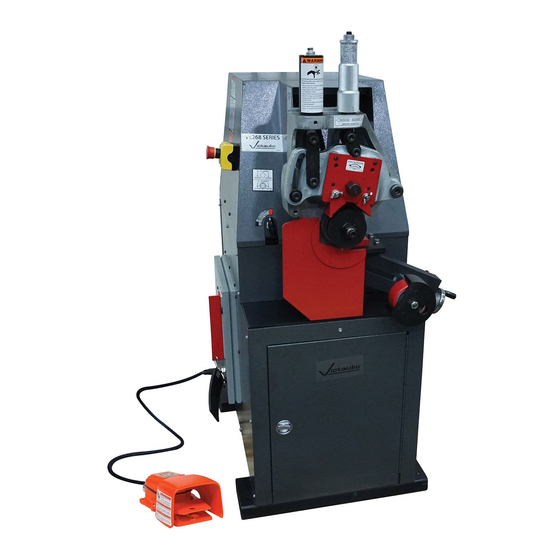
OPERATING AND MAINTENANCE INSTRUCTIONS MANUAL
VE268 Pipe Roll Grooving Tool
WARNING
If you need additional copies of any literature, or if you have questions concerning the safe
and proper operation of this tool, contact Victaulic, P.O. Box 31, Easton, PA 18044-0031,
Phone: 1-800-PICK VIC, E-Mail: pickvic@victaulic.com.
REV_H
WARNING
Failure to follow instructions and warnings could result in death,
serious personal injury, property damage, and/or product damage.
• Before operating or servicing any roll grooving tools, read all
instructions in this manual and all warning labels on the tool.
• Wear safety glasses, hardhat, foot protection, and hearing
protection while working around this tool.
• Save this operating and maintenance manual in a place
accessible to all operators of the tool.
Original Instructions
TM-VE268
OGS
OGS-200
EndSeal
™
TM-VE268
Advertisement
Table of Contents

Related Manuals for Victaulic EndSeal OGS-200


Summary of Contents for Victaulic EndSeal OGS-200
- Page 1 If you need additional copies of any literature, or if you have questions concerning the safe and proper operation of this tool, contact Victaulic, P.O. Box 31, Easton, PA 18044-0031, Phone: 1-800-PICK VIC, E-Mail: pickvic@victaulic.com.
-
Page 3: Table Of Contents
TM-VE268 / Operating and Maintenance Instructions Manual TABLE OF CONTENTS Maintenance ..... . 38 Recommended Lubricants ... . 43 Hazard Identification . -
Page 4: Hazard Identification
Make this manual readily available in a clean, identifies possible hazards or unsafe dry area. Additional copies are available upon practices that could result in personal request through Victaulic, or can be downloaded injury and product or property damage at victaulic.com. if instructions, including recommended DANGER precautions, are not followed. - Page 5 Do not over-reach. Maintain proper footing 10. Use only Victaulic replacement parts and balance at all times. Ensure that the and accessories. Use of any other parts safety foot switch is easily accessible to the may result in a voided warranty, improper operator.
-
Page 6: Introduction
Victaulic. patented features that are the exclusive property of Victaulic. CONTAINER CONTENTS The Victaulic VE268 Roll Grooving Tool is a fully Qty. Description motorized, semi-automatic, hydraulic-feed tool VE268 Pipe Roll Grooving Tool for roll grooving pipe to receive Victaulic grooved Lower Roll for 2 to 3 1/2-inch/60.3 to 101.6-mm... -
Page 7: Power Requirements
R-301-268-SCH • BEARING LUBE – ANTI-WEAR, EXTREME PRESSURE NLGI GRADE 2 REVISION LEVEL Failure to follow these instructions could Victaulic Company World Headquarters Manufactured in Canada 4901 Kesslersville Road • Easton, PA 18040 result in death or serious personal injury. -
Page 8: Tool Nomenclature
If you need additional copies of any literature, or if you have questions concerning the safe and proper Grooving rolls can crush or cut ngers operation of any pipe preparation tools, contact Victaulic, P.O. Box 31, Easton, PA 18044-0031, Phone and hands. -
Page 9: Tool Dimensions And Specifications
TM-VE268 / Operating and Maintenance Instructions Manual TOOL DIMENSIONS AND SPECIFICATIONS 35.60 in/ 27.00 in/ 905 mm 686 mm 13.75 in/ 350 mm 55.00 in/ 1397 mm 50.00 in/ 36.62 in/ 1270 mm 930 mm 22.00 in/559 mm 22.75 in/705 mm Mounting Holes Mounting Holes 24.00 in/... -
Page 10: Tool Setup
“ENABLE” button has been pressed. • If the motor energizes from a cold start without first being enabled, discontinue use and contact Victaulic. 2. The VE268 tool is designed for use in a Failure to follow this instruction could result permanent location and must be located on a in serious personal injury. - Page 11 6b. Turn off the main power supply to the tool (main breaker panel, knife switch, etc.). Lock the switch in the “OFF” position to prevent accidental engagement. NOTE: Victaulic does not supply this lockout mechanism. Reverse any two of the three power leads at the power source.
-
Page 12: Emergency Stop Operation
• If the motor can be energized while the emergency stop button is activated, discontinue use and contact Victaulic. Failure to follow this instruction could result in serious personal injury or death. 2. Press the “ENABLE” button. - Page 13 “NORMAL” position. The tool head stop without first being enabled, should lower when the footswitch is depressed, discontinue use and contact Victaulic. and rise to its resting position when the Failure to follow this instruction could result footswitch is released.
-
Page 14: Preparing Pipe For Grooving
Foreign material may interfere with or Roll groove a 19-foot, 6-inch/5.9-m length damage grooving rolls, resulting in distorted of pipe and a 10-inch/255-mm length of grooves and grooves that are out of Victaulic pipe. Refer to the “Grooving Long Pipe specifications. Lengths” section. - Page 15 TM-VE268 / Operating and Maintenance Instructions Manual TABLE 1- PIPE LENGTHS SUITABLE FOR GROOVING Pipe Size Length – inches/mm Pipe Size Length – inches/mm Nominal Nominal Pipe Size Actual Outside Pipe Size Actual Outside inches or Diameter inches or Diameter inches/mm Minimum Maximum...
-
Page 16: Checking And Adjusting The Tool Prior To Grooving
SELECTOR VALVE SETTING TOOL PRIOR TO GROOVING The groove diameter stop must be adjusted Every Victaulic roll grooving tool is checked, for each pipe size or change in wall thickness. adjusted, and tested at the factory prior to The groove diameter, which is identified as the shipment. - Page 17 TM-VE268 / Operating and Maintenance Instructions Manual Set the selector valve on the front of the 3a. Unlock the depth adjuster from the depth tool to the color that matches the pipe size adjuster lock. and schedule (RED or BLACK) on the pipe size indicator label.
- Page 18 • Always groove pipe in a CLOCKWISE • The “C” dimension (groove diameter) direction. must conform to Victaulic specifications • Never groove pipe that is shorter than to ensure proper joint performance. the recommended lengths listed in this Failure to follow this instruction could cause manual.
-
Page 19: Adjusting The Roll Guards
TM-VE268 / Operating and Maintenance Instructions Manual ADJUSTING THE ROLL GUARDS 8a. If the groove diameter (“C” dimension) is not within Victaulic specifications, the The VE268 guards must be adjusted when diameter stop must be adjusted. rolls are changed or when the pipe size or 8b. - Page 20 TM-VE268 / Operating and Maintenance Instructions Manual WARNING Grooving rolls can crush or cut fingers and hands. • Loading/unloading pipe will place your hands close to the rollers. Keep hands away from the grooving rolls and the roller on the pipe stabilizer.
-
Page 21: Pipe Stabilizer Adjustment
TM-VE268 / Operating and Maintenance Instructions Manual CAUTION • Use the “JOG” mode only for making adjustments to the tool and for roll changes. When the tool is left in “JOG” mode with the power on, the pipe will gradually release and fall out of the tool. •... - Page 22 TM-VE268 / Operating and Maintenance Instructions Manual 1. Ensure that the proper roll set is installed Insert a length of pipe that is the correct on the tool for the pipe size and material to be size and schedule over the lower roll. grooved.
- Page 23 TM-VE268 / Operating and Maintenance Instructions Manual Turn the power switch on the side of the tool to the “ON” position. Turn the selector switch on the side of the tool to the “JOG” position. CORRECT INCORRECT Using the stabilizer handwheel, adjust the stabilizer roller inward to the correct position (shown in the drawing above).
-
Page 24: Ram Speed Control Valve Adjustment
TM-VE268 / Operating and Maintenance Instructions Manual RAM SPEED CONTROL VALVE CAUTION ADJUSTMENT • Use the “JOG” mode only for making adjustments to the tool and for roll changes. When the tool is left in “JOG” mode with the power on, the pipe will gradually release and fall out of the tool. -
Page 25: Grooving Short Pipe Lengths
TM-VE268 / Operating and Maintenance Instructions Manual GROOVING SHORT PIPE LENGTHS CAUTION • This tool must be used ONLY for roll grooving pipe designated in the applicable “Tool Rating and Roll Selection” section of this manual. Failure to follow this instruction could overload the tool, resulting in reduced tool life and/or damage to the tool. - Page 26 TM-VE268 / Operating and Maintenance Instructions Manual WARNING Grooving rolls can crush or cut fingers and hands. • Always turn off the main power supply to the tool before making any tool adjustments. • Loading/unloading pipe will place your hands close to the rollers. Keep hands away from the grooving rolls and the roller on the pipe stabilizer during While manually supporting the pipe,...
-
Page 27: Grooving Long Pipe Lengths
TM-VE268 / Operating and Maintenance Instructions Manual Ensure that the tool is level. Refer to the “Tool Setup” section for leveling requirements. Tool Centerline (level) Pipe 10. If no more roll grooving will be performed Centerline ½° to 1° for a while, turn the power switch on the 2 to 4 inches/ side of the tool to the “OFF”... - Page 28 TM-VE268 / Operating and Maintenance Instructions Manual Turn on the main power supply to the tool WARNING (main breaker panel, knife switch, etc.). Grooving rolls can crush or cut fingers and hands. • Always turn off the main power supply to the tool before making any tool adjustments.
- Page 29 TM-VE268 / Operating and Maintenance Instructions Manual 13a. Continue the grooving process until the depth adjuster lock comes into contact 10. The operator should be positioned as with the top of the tool body. Continue pipe shown above. rotation for several revolutions to ensure groove com pletion.
-
Page 30: Roll Changing
TM-VE268 / Operating and Maintenance Instructions Manual ROLL CHANGING VE268 Roll Grooving Tools are designed with rolls to accommodate several pipe sizes and materials, which eliminates the need for frequent roll changes. When a different pipe size or material is required for grooving, the upper and lower rolls must be changed. -
Page 31: Lower Roll Removal For 3/4-Inch/26.9-Mm
TM-VE268 / Operating and Maintenance Instructions Manual LOWER ROLL REMOVAL FOR 3/4-INCH/ 26.9-MM AND 1 TO 1 1/2-INCH/33.7 TO 48.3-MM SIZES WARNING • Always turn off the main power supply to the tool before changing the rolls. Failure to follow this instruction could result in serious personal injury. -
Page 32: Lower Roll Removal For 2-Inch/60.3-Mm
TM-VE268 / Operating and Maintenance Instructions Manual LOWER ROLL REMOVAL FOR 2-INCH/ WARNING 60.3-MM AND LARGER SIZES • Use only the aluminum WARNING wedge with a soft-faced hammer for removing the • Always turn off the main power supply to lower roll. -
Page 33: Arbor Removal For 2-Inch/60.3-Mm And Larger Sizes
TM-VE268 / Operating and Maintenance Instructions Manual ARBOR REMOVAL FOR 2-INCH/60.3-MM CAUTION AND LARGER SIZES • Never operate the tool with jack bolts Remove the lower roll from the tool by installed in the arbor. referring to the “Lower Roll Removal for Failure to follow this instruction could result 2-inch/60.3-mm and Larger Sizes”... -
Page 34: Upper Roll Installation - All Sizes
TM-VE268 / Operating and Maintenance Instructions Manual UPPER ROLL INSTALLATION – ALL SIZES Insert the upper roll bolt, and tighten it securely with a wrench. Prior to installation, clean all shaft surfaces and roll bores to remove any dirt and scale. Lubricate upper roll bearing. -
Page 35: Lower Roll Assembly Installation For
TM-VE268 / Operating and Maintenance Instructions Manual LOWER ROLL ASSEMBLY INSTALLATION ARBOR INSTALLATION PROCEDURE FOR FOR 3/4-INCH/26.9-MM AND 1 TO 2-INCH/60.3-MM AND LARGER SIZES 1 1/2-INCH/33.7 TO 48.3-MM SIZES Clean the bore of the main shaft and the Clean the bore of the main shaft and the arbor with a soft cloth. -
Page 36: Lower Roll Installation For 2-Inch/60.3-Mm And Larger Sizes
TM-VE268 / Operating and Maintenance Instructions Manual LOWER ROLL INSTALLATION FOR TRAVEL STOP KNOB INSTALLATION 2-INCH/60.3-MM AND LARGER SIZES This applies for the following sizes: 3/4 inch/26.9 mm NPS size NOTICE 1 to 11/2 inch/33.7 to 48.3 mm NPS sizes 2 to 31/2 inch/60.3 to 101.6 mm NPS sizes •... - Page 37 TM-VE268 / Operating and Maintenance Instructions Manual WARNING Grooving rolls can crush or cut fingers and hands. • Loading/unloading pipe will place your hands close to the rollers. Keep hands away from the grooving rolls and the roller on the pipe stabilizer.
-
Page 38: Maintenance
Preventive maintenance during operation will pay for itself in repair and operating savings. Replacement parts must be ordered from Victaulic to ensure proper and safe operation of the tool. LUBRICATION After every 8 hours of operation, lubricate the tool. - Page 39 A heavy-duty spray lubricant may be used, (mechanical assembly spray, supplied with or grease may be applied by hand. Refer to the tool and available from Victaulic). the applicable “Recommended Lubricants” 5d. Reassemble the 3/4-inch/26.9 and table for the proper grease.
- Page 40 TM-VE268 / Operating and Maintenance Instructions Manual REPLACING HYDRAULIC OIL AND FILTER Replace the drain plug in the hydraulic line next to the tank. Check the hydraulic oil level after every 50 Add recommended hydraulic oil to no hours of operation, preferably before tool higher than 1/2 inch/13 mm from the top startup.
- Page 41 TM-VE268 / Operating and Maintenance Instructions Manual 7. Depress the safety foot switch and observe With the hydraulic breather cap on top of the hydraulic fluid flowing through the clear the hydraulic tank removed, insert the end bleeder tube. The hydraulic fluid should contain of the clear bleeder tube into the hydraulic air bubbles.
- Page 42 TM-VE268 / Operating and Maintenance Instructions Manual 12. Turn the selector switch on the side of the tool to the “NORMAL” position. Add recommended hydraulic oil to no higher than 1/2 inch/13 mm from the top WARNING of the tank. Refer to the “Recommended Lubricants”...
-
Page 43: Recommended Lubricants
TM-VE268 / Operating and Maintenance Instructions Manual RECOMMENDED LUBRICANTS BEARING AND SLIDE GREASE (General Purpose EP Lithium Base Grease) Manufacturer Product Energrease LC-EP2 BP Amoco Gulfcrown Grease EP#2 Gulf Oil Corp. No. 630-2 Lubriplate 16. Turn the power switch on the side of the Mobilux EP2 Mobil Oil Corp. -
Page 44: Legacy Tool Features
KEYLESS ARBORS AND UNIVERSAL LOWER ROLLS In the 1990s, Victaulic introduced an improved “keyless” method for transmitting grooving power between the arbor and lower roll. This “keyless” design applies to the lower rolls and arbor only. -
Page 45: Accessories
When ordering parts, the following information both pipe ends. Contact Victaulic for details. is required for Victaulic to process the order and send the correct part(s). Request the RP-VE268 OPTIONAL ROLLS Repair Parts List for detailed drawings and parts Refer to the applicable “Tool Rating and Roll... -
Page 46: Troubleshooting
TM-VE268 / Operating and Maintenance Instructions Manual TROUBLESHOOTING PROBLEM POSSIBLE CAUSE SOLUTION Pipe will not stay in grooving Incorrect pipe positioning of long pipe Refer to the “Grooving Long Pipe Lengths” section. rolls. length. Lower roll and pipe are not rotating Refer to the “Power Hookup and Verification of Pipe Rotation clockwise. - Page 47 Make sure pipe is against the lower-roll backstop flange. Refer to or pipe is not tracking properly. the “Grooving Long Pipe Lengths” section for proper pipe stand positioning. In the event of tool malfunction outside the scope of the troubleshooting section, contact Victaulic for assistance. REV_H TM-VE268_47...
-
Page 48: Tool Rating And Roll Selection
In addition, the following pipe sizes may be roll grooved: 76.1 mm; 108.0 mm; 133.0 mm; 139.7 mm; 152.4 mm; 159.0 mm; 165.1 mm; 203.2 mm; 216.3 mm; 254.0 mm; 267.4 mm; 304.8 mm; and 318.5 mm. Contact Victaulic for details. REV_H... -
Page 49: Original Groove System Rolls For Aluminum And Pvc Plastic Pipe
318.5 mm. Contact Victaulic for details. For PVC pipe, the following additional pipe sizes may be roll grooved: 76.1 mm; 108.0 mm; 133.0 mm; 139.7 mm; 159.0 mm; 165.1 mm; and 216.3 mm. Contact Victaulic for details. REV_H TM-VE268_49... -
Page 50: Original Groove System Rx Rolls For Schedule 5S And 10S Stainless Steel Pipe
TM-VE268 / Operating and Maintenance Instructions Manual ORIGINAL GROOVE SYSTEM RX ROLLS FOR SCHEDULE 5S AND 10S STAINLESS STEEL PIPE – COLOR CODED SILVER Dimensions Pipe Size inches/millimeters Stainless Steel Pipe Wall Thickness Actual Nominal Outside Diameter Minimum for Maximum for Roll Size inches inches/mm... -
Page 51: Rolls For Cts Us Standard
0.271 RR08272L08 206.4 Upper Roll RRA2272U08 * ASTM B306, Type DWV and ASTM B88, Types K, L, M copper tubing. For grooving copper tubing to other standards, contact Victaulic. The wall thicknesses listed are nominal minimum and maximum. REV_H TM-VE268_51... -
Page 52: Explanation Of Critical Roll Groove Dimensions
NOTICE FOR STANDARD COUPLINGS WITH RATINGS ON LIGHT-WALL STAINLESS STEEL PIPE: • Victaulic RX rolls MUST be used when roll grooving light-wall stainless steel pipe for use with standard couplings. Pipe Outside Diameter – Nominal NPS Pipe Size (ANSI B36.10) and Basic Metric Pipe Size (ISO 4200) –... - Page 53 “T” Dimension – The “T” dimension is the lightest grade (minimum nominal wall thickness) of pipe that is suitable for cut or roll grooving. Pipe that is less than the minimum nominal wall thickness for cut grooving may be suitable for roll grooving or adapted for Victaulic couplings by using Vic-Ring ®...
-
Page 54: Roll Groove Specifications
TM-VE268 / Operating and Maintenance Instructions Manual REV_H TM-VE268_54... - Page 55 TM-VE268 / Operating and Maintenance Instructions Manual REV_H TM-VE268_55...
- Page 56 TM-VE268 / Operating and Maintenance Instructions Manual REV_H TM-VE268_56...
-
Page 57: Original Groove System For Steel Pipe And All Materials Grooved With "Es" Rolls
TM-VE268 / Operating and Maintenance Instructions Manual REV_H TM-VE268_57... -
Page 58: Copper Tubing
TM-VE268 / Operating and Maintenance Instructions Manual REV_H TM-VE268_58... -
Page 59: European Standard - En 1057 Copper Tubing
TM-VE268 / Operating and Maintenance Instructions Manual REV_H TM-VE268_59... -
Page 60: Australian Standard - As 1432 Copper Tubing
TM-VE268 / Operating and Maintenance Instructions Manual REV_H TM-VE268_60... - Page 61 TM-VE268 / Operating and Maintenance Instructions Manual This page intentionally blank REV_H TM-VE268_61...
-
Page 62: Ec Declaration Of Conformity
Signed for and on behalf of Victaulic Company, Mr. Len R. Swantek Director – Global Regulatory Compliance Machinery Manufacturer Representative Place of Issue: Easton, Pennsylvania, USA Date of Issue: November 20, 2019 MD_DoC_RGT_008_112019_en.docx VICTAULIC IS A REGISTERED TRADEMARK OF VICTAULIC COMPANY. ©2013 VICTAULIC COMPANY. ALL RIGHTS RESERVED... -
Page 63: Ukca Declaration Of Conformity
Director – Global Regulatory Compliance Machinery Manufacturer Representative Place of Issue: Easton, Pennsylvania, USA Date of Issue: May 14, 2021 Victaulic and all other Victaulic marks and logos are registered trademarks of Victaulic Company and/or its affiliates. ©2021 All Rights Reserved... - Page 64 OPERATING AND MAINTENANCE INSTRUCTIONS MANUAL VE268 Pipe Roll Grooving Tool UPDATED 09/2021 TM-VE268 2468 REV H RM00268000 VICTAULIC IS A REGISTERED TRADEMARK OF VICTAULIC COMPANY AND/OR ITS AFFILIATED ENTITIES IN THE UNITED STATES AND/OR OTHER COUNTRIES. © 2021 VICTAULIC COMPANY. ALL RIGHTS RESERVED.
Need help?
Do you have a question about the EndSeal OGS-200 and is the answer not in the manual?
Questions and answers